Advertisement
Quick Links
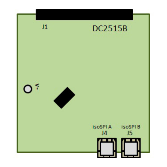
DESCRIPTION
Demonstration circuit 2515B features the
6-channel battery-stack monitor. Multiple boards can be
linked through a 2-wire isolated serial interface (isoSPI™)
to monitor a long series of cells in a stack. The DC2515B
demo board also features reversible isoSPI enabling a
redundant communication path. The PCB, components,
and DuraClik connectors are optimized for Low EMI
Susceptibility and Emissions.
The DC2515B can communicate to a PC by connecting
a DC2792B dual master isoSPI together with DC2026
PERFORMANCE SUMMARY
PARAMETER
+
V
Supply Voltage
+
V
to C6 Voltage
C0/S0 Voltage
V
Supply Voltage
REG
V
1st Reference Voltage, No Load
REF1
V
2nd Reference Voltage, 5k Load to V
REF2
V
IBIAS Voltage, READY/ACTIVE State
BIAS
C
Input Range
PIN
Cell Count
Arrow.com.
Downloaded from
6-Channel Battery-Stack Monitor
LTC
6810-1, a
®
Specifications are at T
–
DEMO MANUAL DC2515B
with Daisy-Chain Interface
Linduino
One. The DC2026 must be loaded with the
®
appropriate program (called a sketch) to control the bat-
tery stack monitor IC and receive data through a USB
serial port. The DC2026C provides a standard SPI inter-
face which can be translated to isoSPI and then con-
nected to a DC2515B isoSPI port (J4 or J5 connector).
The DC2792B companion board provides two SPI-isoSPI
channels for reversible operation.
Design files for this circuit board are
All registered trademarks and trademarks are the property of their respective owners.
= 25°C
A
LTC6810-1
available.
MIN
TYP
MAX
UNITS
5.0
20
27.5
–0.3
0
5
4.5
5
5.5
3.1
3.2
3.3
2.994
3
3.006
1.9
2.0
2.1
0
5
6
V
V
V
V
V
V
V
V
Rev. 0
1
Advertisement

Related Manuals for Analog Devices DC2515B


Summary of Contents for Analog Devices DC2515B
- Page 1 2-wire isolated serial interface (isoSPI™) tery stack monitor IC and receive data through a USB to monitor a long series of cells in a stack. The DC2515B serial port. The DC2026C provides a standard SPI inter- demo board also features reversible isoSPI enabling a face which can be translated to isoSPI and then con- redundant communication path.
-
Page 2: Hardware Setup
When connected to a battery-stack, power for the – C0/V DC2515B is provided by the cell group being monitored. To connect the cell group, separate the screw-terminal block section from the J1 connector. Then, insert the cell- voltage connections or resistors into the screw-terminal clamping contacts. - Page 3 PC with the Arduino IDE software is the first (or bottom) board of the stack. to allow communication to the DC2515B boards. Figure 2. DC2792B Typical isoSPI Connection to the Bottom DC2515B in a Two-Board DC2515B Stack Rev. 0 Arrow.com.
- Page 4 (or main) isoSPI Master connected to the first (or bot- tom) DC2515B and has a backup auxiliary (or aux) isoSPI Figure 3. DC2792B Reverse isoSPI Connection to the Top DC2515B in a Two-Board DC2515B Stack Rev. 0 Arrow.com.
- Page 5 PC with the Arduino IDE software release from the DuraClik receptacles. Failure to do to allow communication to the DC2515B boards. Figure 4. DC2792B Redundant isoSPI Connections to the Bottom and Top DC2515B in a Two-Board DC2515B Stack Rev. 0 Arrow.com.
-
Page 6: Software Setup
DEMO MANUAL DC2515B SOFTWARE SETUP The DC2515B can be controlled with the DC2026 Linduino One board together with DC2792B dual isoSPI Master or equivalent isoSPI transceiver. The DC2026 is part of the Arduino compatible Linduino platform that provides example code that will demonstrate how to control the multicell battery-stack monitor ICs. Compared to most Arduino compat-... - Page 7 DEMO MANUAL DC2515B SOFTWARE SETUP 3. Close then re-open the Arduino IDE to enable the use of the Sketchbook Location that was previously set. 4. Select the correct COM port to allow communication to DC2026 through USB. Under the Tools menu, select Port Select the highest number COMxx with the ✓...
- Page 8 DEMO MANUAL DC2515B SOFTWARE SETUP 6. Open one of the programs or sketches associated with the DC2515B. In this example LTC6810 sketch will be opened. Under the File menu, select Sketchbook Part Number 6000 6810 DC2515 (see Figure 8). ➞ ➞...
- Page 9 DEMO MANUAL DC2515B SOFTWARE SETUP 7. Upload the DC2515 sketch onto the DC2026 by clicking on the Upload button on the top left corner. When this process is completed there will be a Done Uploading message on the bottom left corner (see Figure 9).
- Page 10 DEMO MANUAL DC2515B SOFTWARE SETUP 9. Configure the Serial Monitor to allow communication to the DC2026 through USB. On the bottom of the Serial Monitor window, set the following starting from bottom left to bottom right: a. Click on the Autoscroll checkbox for the ✓ check mark symbol.
-
Page 11: Appendix A: The Sketchbook Contents
These files contain all of the constant definitions and Utilities directory: Contains support programs, includ- low-level IC command implementations. Porting to a differ- ing a program that emulates a standard Analog Devices ent microcontroller requires changes to some library files. DC590 isolated USB to serial controller. - Page 12 DEMO MANUAL DC2515B APPENDIX A: THE SKETCHBOOK CONTENTS What Is A Sketch and 4 should be entered. In an application that has 2 devices in the network the modified line will look like A sketch is simply another word for a microcontroller/ the following.
- Page 13 Devices for its use, nor for any infringements of patents or other rights of third parties that may result from its use. Specifications subject to change without notice. No license is granted by implication or otherwise under any patent or patent rights of Analog Devices.
- Page 14 Board until you have read and agreed to the Agreement. Your use of the Evaluation Board shall signify your acceptance of the Agreement. This Agreement is made by and between you (“Customer”) and Analog Devices, Inc. (“ADI”), with its principal place of business at One Technology Way, Norwood, MA 02062, USA. Subject to the terms and conditions of the Agreement, ADI hereby grants to Customer a free, limited, personal, temporary, non-exclusive, non-sublicensable, non-transferable license to use the Evaluation Board FOR EVALUATION PURPOSES ONLY.
Need help?
Do you have a question about the DC2515B and is the answer not in the manual?
Questions and answers