Advertisement
Quick Links
DESCRIPTION
Demonstration circuit 2569A is ultrathin step-up µModule
regulator featuring the LTM4661. The DC2569A operates
over 1.8V to 5.5V input and it generates 12V, 1A output
from 5V input. Also, the LTM4661 has precision voltage
reference, which can generate output voltage with 3%
tolerance over the full operating conditions. The 1MHz
switching frequency operation results in small and effi-
cient circuit. The converter operates with only one phase
in burst mode and achieves over 90% efficiency with
PERFORMANCE SUMMARY
PARAMETER
Minimum Input Voltage
Maximum Input Voltage
V
OUT
Output Voltage Ripple
Nominal Switching Frequency
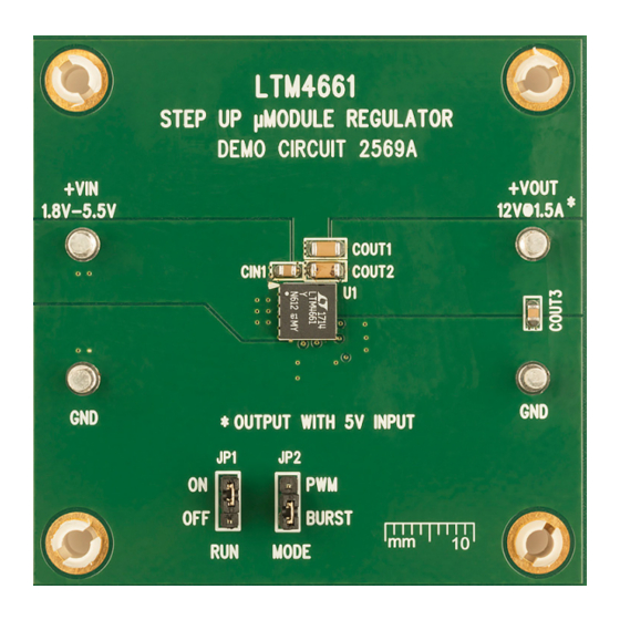
BOARD PHOTO
Arrow.com.
Downloaded from
Synchronous Step-Up µModule Regulator
Specifications are at T
CONDITIONS
I
= 0A to 0.3A
OUT
I
= 0A to 1A
OUT
V
= 1.8V to 5.5V, I
IN
V
= 5V, I
IN
OUT
DEMO MANUAL DC2569A
100mA load. The demonstration circuit can be easily
modified to generate different output voltages.
The DC2569 has small circuit footprint. It is a high perfor-
mance and cost effective solution for generating output
voltages up to 15V from inputs as low as 1.8V.
Design files for this circuit board are available at
http://www.linear.com/demo/DC2569A
All registered trademarks and trademarks are the property of their respective owners.
= 25°C
A
= 0A
OUT
= 1A
LTM4661
1.8V-5.5V Input,
VALUE
1.8V
5.5V
12V ±3%
20mV
P-P
1MHz
dc2569af
1
Advertisement

Subscribe to Our Youtube Channel
Related Manuals for Analog Devices DC2569A


Summary of Contents for Analog Devices DC2569A
- Page 1 DESCRIPTION Demonstration circuit 2569A is ultrathin step-up µModule 100mA load. The demonstration circuit can be easily regulator featuring the LTM4661. The DC2569A operates modified to generate different output voltages. over 1.8V to 5.5V input and it generates 12V, 1A output The DC2569 has small circuit footprint.
- Page 2 DEMO MANUAL DC2569A QUICK START PROCEDURE Demonstration circuit DC2569 is easy to set up to evaluate 3. Turn the input power source on and slowly increase the the performance of the LTM4661. For proper measure- input voltage. Be careful not to exceed 5.5V.
- Page 3 Typi- load transients to desired level. cal performance of DC2569A is shown in Figure 3. As can be seen from Figure 3, the maximum output current is 1A with 5V input. Switching the mode of operation to BURST mode can increase the efficiency at light loads.
-
Page 4: Output Short Circuit Protection
DEMO MANUAL DC2569A QUICK START PROCEDURE OUTPUT SHORT CIRCUIT PROTECTION The LTM4661 features safe short-circuit and thermal pro- 200mA/DIV tection. The part can operate continuously with output 2V/DIV shorted while maintaining a maximum set current limit. The internal peak switch current is reduced during over- 10V/DIV load to about 2A and is restored to 3.5A once the output... -
Page 5: Schematic Diagram
DEMO MANUAL DC2569A SCHEMATIC DIAGRAM dc2569af Information furnished by Linear Technology Corporation is believed to be accurate and reliable. However, no responsibility is assumed for its use. Linear Technology Corporation makes no representa- tion that the interconnection of its circuits as described herein will not infringe on existing patent rights. - Page 6 DEMO MANUAL DC2569A DEMONSTRATION BOARD IMPORTANT NOTICE Linear Technology Corporation (LTC) provides the enclosed product(s) under the following AS IS conditions: This demonstration board (DEMO BOARD) kit being sold or provided by Linear Technology is intended for use for ENGINEERING DEVELOPMENT OR EVALUATION PURPOSES ONLY and is not provided by LTC for commercial use.
Need help?
Do you have a question about the DC2569A and is the answer not in the manual?
Questions and answers