Advertisement
Quick Links
DESCRIPTION
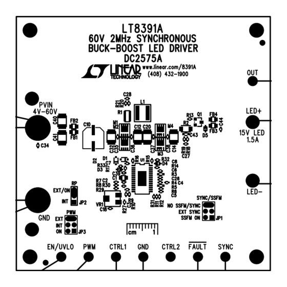
Demonstration circuit DC2575A is a 60V 2MHz synchro-
nous buck-boost LED driver featuring the LT8391A. It
accepts an input voltage from 4V to 60V and drives a
single string of LEDs up to 16V at 1.5A. DC2575A runs at
2MHz switching frequency and features spread spectrum
frequency modulation (SSFM) which can be enabled with
a simple jumper. SSFM spreads the switching frequency
from f
to f
+25% for reduced EMI. SSFM is not nec-
SW
SW
essary in applications where EMI is not important.
DC2575A uses AEC-Q automotive-approved components
such as power MOSFETs, diodes, input and output capaci-
tors and inductors.
The LT8391A has an adjustable switching frequency
between 600kHz and 2MHz. The jumper also allows exter-
nal frequency synchronization.
The LT8391A can be PWM dimmed with an external PWM
signal and an internally-generated PWM signal. DC2575A
has a jumper that can be set to switch between internally-
generated PWM signal, externally-generated PWM signal,
and no PWM signal (100% on). It can be analog dimmed
with a control voltage on either of its two control pins.
When run with both PWM dimming and spread spectrum,
the spread spectrum aligns itself with the PWM signal for
flicker-free operation.
The LT8391A features both open LED and short LED
+
(LED
to GND) protection as well as a fault output flag.
DEMO MANUAL DC2575A
60V 2MHz Synchronous
1.5A Buck-Boost LED Driver
Small ceramic input and output capacitors are used to
save space and cost. The board is designed with capaci-
tors on both sides of the synchronous switches for a
reduction in radiated EMI. The open LED overvoltage
protection uses the IC's constant voltage regulation loop
to regulate the output to approximately 18V if the LED
string is opened. There is a protection diode from LED
to GND to prevent negative ringing during a short-circuit
with long wires.
Undervoltage lockout can be adjusted on the circuit with
a few simple resistor choices.
EMI filters and gate resistors on the demo circuit reduce
this high power converter's EMI below CISPR 25 Class 5
limits. This is intended for automotive applications where
CISPR 25 EMI standards are observed. In non-automotive
applications, where EMI may not be as important, the
input and output filters as well as the gate resistors can
be removed for higher efficiency. Please note the optional
EMI components in the parts list.
The LT8391A data sheet gives a complete description of
the part, operation and applications information. The data
sheet must be read in conjunction with this Demo Manual
for demonstration circuit DC2575A. The LT8391AIFE is
assembled in a 28-lead plastic TSSOP (FE) package with
a thermally-enhanced ground pad. Proper board layout
is essential for maximum thermal performance. See the
data sheet section "Layout Considerations".
Design files for this circuit board are
All registered trademarks and trademarks are the property of their respective owners.
LT8391AIFE
+
available.
Rev. A
1
Advertisement

Subscribe to Our Youtube Channel
Related Manuals for Analog Devices DC2575A


Summary of Contents for Analog Devices DC2575A
- Page 1 4V to 60V and drives a tors on both sides of the synchronous switches for a single string of LEDs up to 16V at 1.5A. DC2575A runs at reduction in radiated EMI. The open LED overvoltage 2MHz switching frequency and features spread spectrum protection uses the IC’s constant voltage regulation loop...
- Page 2 DEMO MANUAL DC2575A QUICK START PROCEDURE Table 1. Typical Performance Summary for DC2575A (LT8391A) PARAMETER CONDITIONS Input Voltage PV Range Operating V ≤16V Switching Frequency (f R3 = 59.0k, JP1 = NO SSFM/SYNC 2.0MHz Spread Spectrum (SSFM) Frequency Range JP1 = SSFM ON •...
-
Page 3: Quick Start Procedure
SHUTDOWN EXTERNAL OPTIONAL OPTIONAL ANALOG SYNC DIMMING INTERNAL PWM DIMMING Figure 1. Test Procedure Setup Drawing for DC2575A 16V 1.5A LEDs INPUT VOLTAGE (V) DC2575 F02 Figure 2. DC2575A Efficiency Versus Input Voltage for 16V 1.5A LED Load Rev. A... - Page 4 DEMO MANUAL DC2575A QUICK START PROCEDURE WITH DC2575A EMI FILTERS 16V 1.5A LEDs 2000:1 100Hz PWM EXTERNAL VPWM 1A/DIV WITH DC2575A EMI FILTERS 16V 1.5A LEDs VPWM 128:1 500Hz PWM INTERNAL 1A/DIV Figure 3. Infinite-Persist Scope Traces Show PWM Dimming and SSFM Working Together for Flicker-Free Brightness Control with Both (a) Externally- and (b) Internally-Generated PWM Dimming (with EMI Filters) Rev.
- Page 5 DEMO MANUAL DC2575A QUICK START PROCEDURE WITHOUT DC2575A EMI FILTERS 16V 1.5A LEDs 2000:1 100Hz PWM EXTERNAL VPWM 1A/DIV WITHOUT DC2575A EMI FILTERS 16V 1.5A LEDs VPWM 128:1 500Hz PWM INTERNAL 1A/DIV Figure 4. Infinite-Persist Scope Traces Show PWM Dimming and SSFM Working Together for Flicker-Free Brightness Control with Both (a) Externally- and (b) Internally-Generated PWM Dimming (with EMI Filters Removed) Rev.
- Page 6 16V 1.5A LEDs CISPR 25 CLASS 5 16V 1.5A LEDs CISPR 25 CLASS 5 RADIATED EMI LIMITS RADIATED EMI LIMITS 2MHz 2MHz –10 –10 1000 DC2575 F05d DC2575 F05c Figure 5. DC2575A (LT8391A) Passes CISPR 25 Class 5 Radiated EMI Rev. A...
-
Page 7: Parts List
DEMO MANUAL DC2575A PARTS LIST ITEM REFERENCE PART DESCRIPTION MANUFACTURER/PART NUMBER Required Circuit Components CAP ., 1µF, X7S, 100V, 10%, 0805 MURATA, GRJ21BC72A105KE11L CAP ., 4.7µF, X5R, 10V, 10%, 0402 TDK, C1005X5R1A475K050BC CAP ., 0.47µF, X5R, 16V, 10%, 0402 TAIYO YUDEN, EMK105ABJ474KV-F CAP ., 3300pF, X7R, 16V, 10%, 0402... - Page 8 DEMO MANUAL DC2575A PARTS LIST ITEM REFERENCE PART DESCRIPTION MANUFACTURER/PART NUMBER Other Optional Electrical Components C18, C26, C27, C28, CAP ., OPTION, 0402 C39 (OPT) C29, C30 (OPT) CAP ., 0805, OPTION C43 (OPT) CAP ., OPTION, 0603 DIODE, SCHOTTKY, 30V, 1A, SOD523-2, AEC-Q101...
-
Page 9: Schematic Diagram
Devices for its use, nor for any infringements of patents or other rights of third parties that may result from its use. Specifications subject to change without notice. No license is granted by implication or otherwise under any patent or patent rights of Analog Devices. - Page 10 Board until you have read and agreed to the Agreement. Your use of the Evaluation Board shall signify your acceptance of the Agreement. This Agreement is made by and between you (“Customer”) and Analog Devices, Inc. (“ADI”), with its principal place of business at One Technology Way, Norwood, MA 02062, USA. Subject to the terms and conditions of the Agreement, ADI hereby grants to Customer a free, limited, personal, temporary, non-exclusive, non-sublicensable, non-transferable license to use the Evaluation Board FOR EVALUATION PURPOSES ONLY.
Need help?
Do you have a question about the DC2575A and is the answer not in the manual?
Questions and answers