Raymarine i60 Installation Instructions Manual
Long & short arm wind vane
Hide thumbs
Also See for i60:
- Manual (104 pages) ,
- Installation & operation instructions (76 pages) ,
- Installation and operation instructions manual (70 pages)

Related Manuals for Raymarine i60


Summary of Contents for Raymarine i60
- Page 1 Long & Short Arm Wind Vane Installation instructions English (en-US) Date: 10-2019 Document number: 87220-2 © 2019 Raymarine UK Limited...
- Page 3 Software updates Check the Raymarine website for the latest software releases for your product. www.raymarine.com/software Product documentation The latest versions of all English and translated documents are available to download in PDF format from the website: www.raymarine.com/manuals.
-
Page 5: Table Of Contents
Contents Chapter 1 Important information..................7 Water ingress ..........................7 Disclaimer ............................7 Declaration of conformity......................7 Warranty registration ......................... 8 Product disposal ........................8 IMO and SOLAS ......................... 8 Technical accuracy ........................8 Chapter 2 Document and product information............. 9 2.1 Product documentation...................... 10 Operation instructions ...................... - Page 6 7.1 Wind vane routine checks ....................36 Wind Vane maintenance.......................36 7.2 Unit cleaning instructions ....................36 Chapter 8 Technical support ..................37 8.1 Raymarine product support and servicing ..............38 8.2 Learning resources ......................39 Chapter 9 Technical specification.................. 41 9.1 Physical specification......................42 9.2 Conformance specification ....................
-
Page 7: Chapter 1 Important Information
Raymarine. Raymarine is not responsible for damages or injuries caused by your use or inability to use the product, by the interaction of the product with products manufactured by others, or by errors in information utilized by the product supplied by third parties. -
Page 8: Warranty Registration
In addition, our policy of continuous product improvement may change specifications without notice. As a result, Raymarine cannot accept liability for any differences between the product and this document. Please check the Raymarine website (www.raymarine.com) to ensure you have... -
Page 9: Chapter 2 Document And Product Information
Chapter 2: Document and product information Chapter contents • 2.1 Product documentation on page 10 • 2.2 Applicable products on page 10 Document and product information... -
Page 10: Product Documentation
Display software Ensure your display software is updated to the latest version. To updated your display software refer to the operations instructions for your display. For the latest software for your display refer to the Raymarine website: www.raymarine.com/software Document illustrations Your product and if applicable, its user interface may differ slightly from that shown in the illustrations in this document, depending on product variant and date of manufacture. -
Page 11: Wind Vane Replacements
Short arm 300 mm (11.8 in) wind vane transducer with 30 m (98.4 ft) cable — E22078 Provides both wind speed and wind direction data. Long arm 600 mm (23.6 in) wind vane transducer with 50 m (164 ft) cable — E22079 Provides both wind speed and wind direction data. -
Page 12: Compatible Displays
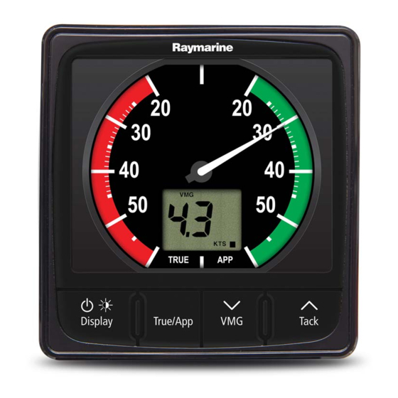
A compatible instrument display is required to calibrate and display wind data from your wind vane transducer. See below for compatible instrument displays. Instrument display Connection method i70 / i70S iTC-5 or transducer pod i60 Wind Direct connection ST70 iTC-5 or transducer pod ST60+ Wind Direct connection... -
Page 13: Compatible Converter And Pods
Compatible converter and pods Wind vane transducers can also be connected to the SeaTalkng ® network using a compatible converter. Wind data will then be available to all displays connected to the same network. iTC-5 (E70010). 2. ST70 (E22108) / ST290 (E22068) wind transducer pod. Parts supplied —... -
Page 14: Parts Supplied - Replacement Wind Vane Assembly
Documentation pack 8. 4 mm drill bit 9. No 4x3/8” pan head pozi screws (junction box fixings x 6) 10. No 10x3/4” pan head pozi screws (base mounting fixings x 2) 11. Junction box grommets x 2 12. 40 mm x 4 mm protective sleeve x 2 Note: Fixings are provided for various installation scenarios, you do not need to use all of the supplied fixings to install your wind transducer. -
Page 15: Chapter 3 Installation
Chapter 3: Installation Chapter contents • 3.1 Tools required on page 16 • 3.2 Selecting a location on page 16 • 3.3 Mounting on page 17 • 3.4 Replacing an existing wind vane on page 21 Installation... -
Page 16: Tools Required
3.1 Tools required Product installation requires the following tools: Power drill 2. Pozidrive screwdriver 3. Drill bit Note: The appropriate drill bit size is dependent on the thickness and material of the mounting surface. 3.2 Selecting a location Warnings and cautions Important: Before proceeding, ensure that you have read and understood the warnings and cautions provided in the Chapter 1 Important information... -
Page 17: Wind Vane Dimensions
Wind vane dimensions Dimensions for the short and long arm wind vanes are shown below. Short arm Long arm 272 mm (10.70 in) 248 mm (9.76 in) 345.5 mm (13.60 in) 38 mm (1.50 in) 68 mm (2.70 in) 538.5 mm (21.20 in) 803.5 mm (31.63 in) 30 m (98.4 ft) 50 m (164 ft) - Page 18 The unit’s cable can be routed protruding from the rear of the base or underneath the base as shown below: Cable protruding from rear. 2. Cable protruding underneath.
- Page 19 Note: Do NOT remove the protective cap from the base connector until you are ready to fit the wind vane arm. 1. Decide on the cable routing option that suits your installation. 2. Mark the mounting surface based on your cable routing option: i.
-
Page 20: Mounting The Junction Box
12. Use the retaining clip to secure the arm of the wind vane. 13. Route the cable back to the display, using the junction box if required. 14. If you had to remove the spade terminals then new spade terminals (not supplied) must be fitted to each wire. -
Page 21: Replacing An Existing Wind Vane
3.4 Replacing an existing wind vane When replacing an existing wind vane it is important that the latest hardware design is utilized. When considering what needs replacing there are 3 options. • Option 1 — Replacing wind vane and base. If the wind vane cable is in good condition but your base is an older design then you can replace the wind vane and base using the existing cable. -
Page 22: Improved Base And Protective Cap Design
Improved base and protective cap design The replacement wind vane components utilize an improved design to aid protection against water ingress and prolong the life of your wind vane. New design — The new design has an arm alignment recess instead of a slit through the thread and the new protective cap design includes a tapered collar. -
Page 23: Replacing Wind Vane And Cable
5. Unscrew the cable retention nut and remove from the base. 6. Unscrew the base fixing screws. 7. Remove the base leaving the cable in place. 8. Remove the cable washer from the end of the cable connector. 9. Replace the cable washer with the new one supplied. 10. - Page 24 Note: The tapered collar on the protective cap provides a seal to protect the wind vane cable connector against water ingress and must be used in all installations.
-
Page 25: Chapter 4 Connections
Chapter 4: Connections Chapter contents • 4.1 General cabling guidance on page 26 • 4.2 Cable routing on page 27 • 4.3 Wind vane connections on page 28 Connections... -
Page 26: General Cabling Guidance
• Unless otherwise stated only use cables supplied by Raymarine. • Where it is necessary to use non-Raymarine cables, ensure that they are of correct quality and gauge for their intended purpose. (e.g.: longer power cable runs may require larger wire gauges to minimize voltage drop along the run). -
Page 27: Cable Routing
4.2 Cable routing Routing the cable through the deck mast Follow the steps below to route cable through a deck mast. Wind vane transducer Mast Compatible instrument display Deck Junction box Bulkhead 1. Feed the cable down the mast and out through a suitable below-decks aperture. 2. -
Page 28: Replacing Spade Terminals
Replacing spade terminals Although the transducer cable is fitted with spade terminals for direct connection to a compatible display or converter, it may be necessary to remove these to allow the cable to be routed through bulkheads or masts etc. 5 x 1/8th spade terminals will be required (not supplied), to replace those removed. - Page 29 iTC–5 connection Compatible wind instrument display connection Connections...
- Page 30 Pod (legacy) connection Wire colors / signal Wire color Signal Wind V+ Gray Wind 0 V (Shield) Green Sine wind direction Blue Cosine wind direction Yellow Anemometer (signal)
-
Page 31: Chapter 5 System Checks And Troubleshooting
Chapter 5: System checks and troubleshooting Chapter contents • 5.1 Troubleshooting on page 32 • 5.2 Wind data troubleshooting on page 32 System checks and troubleshooting... -
Page 32: Troubleshooting
If after referring to this section you are still having problems with your product, please refer to the Technical support section of this manual for useful links and Raymarine Product Support contact details. -
Page 33: Chapter 6 Operation
Chapter 6: Operation Chapter contents • 6.1 Calibration and linearization on page 34 • 6.2 Operation instructions on page 34 Operation... -
Page 34: 6.1 Calibration And Linearization
Please refer to the operation instructions that accompanied your compatible wind instrument display for calibration and linearization procedures. 6.2 Operation instructions For detailed operation instructions for your product, refer to the documentation that accompanies your display. All product documentation is available to download from the Raymarine website: www.raymarine.com/manuals. -
Page 35: Chapter 7 Maintenance
Chapter 7: Maintenance Chapter contents • 7.1 Wind vane routine checks on page 36 • 7.2 Unit cleaning instructions on page 36 Maintenance... -
Page 36: Wind Vane Routine Checks
7.1 Wind vane routine checks You should perform the following routine checks of your wind vane transducer: • Check the wind vane arm’s locking collar is tight. • Check that the wind vane arm’s retaining clip is firmly in place. •... -
Page 37: Chapter 8 Technical Support
Chapter 8: Technical support Chapter contents • 8.1 Raymarine product support and servicing on page 38 • 8.2 Learning resources on page 39 Technical support... -
Page 38: 8.1 Raymarine Product Support And Servicing
You can obtain this product information using diagnostic pages of the connected MFD. Servicing and warranty Raymarine offers dedicated service departments for warranty, service, and repairs. Don’t forget to visit the Raymarine website to register your product for extended warranty benefits: http://www.raymarine.co.uk/display/?id=788. Region... -
Page 39: 8.2 Learning Resources
(Authorized Raymarine distributor) • Tel: +7 495 788 0508 8.2 Learning resources Raymarine has produced a range of learning resources to help you get the most out of your products. Video tutorials Raymarine official channel on YouTube: • YouTube LightHouse™... -
Page 41: Chapter 9 Technical Specification
Chapter 9: Technical specification Chapter contents • 9.1 Physical specification on page 42 • 9.2 Conformance specification on page 42 Technical specification... -
Page 42: Physical Specification
9.1 Physical specification Long arm Short arm Weight: • Boxed: 2.5 Kg (5.5 lbs) • Boxed: 3 Kg (6.6 lbs) • Wind vane assembly: 0.2 • Wind vane assembly: 0.22 (0.4 lbs) Kg (0.47 lbs) • Cable assembly: 1.2 Kg (2.6 •... -
Page 43: Chapter 10 Spares And Accessories
Chapter 10: Spares and accessories Chapter contents • 10.1 Wind vane spares and accessories on page 44 Spares and accessories... -
Page 44: 10.1 Wind Vane Spares And Accessories
10.1 Wind vane spares and accessories The following spares and accessories are available for the wind vane transducers. Spares Part number Description R28170 Short arm wind vane assembly (no cable) R28171 Long arm wind vane assembly (no cable) A28159 Wind vane short arm (300 mm) A28160 Wind vane long arm (600 mm) A28161... - Page 47 Index Parts supplied............. 13–14 Connection ............30 Applicable products ..........11 Product dimensions..........17 Product recycling (WEEE) .......... 8 Product support............38 protective cap............19 Cable Protective cap............23 Bend radius............26 Protection ............26 Routing ..............26 Security ..............26 Retaining clip ............20 Strain relief............26 Cable routing............18, 27 Calibration ...............
- Page 50 FLIR Belgium BVBA Luxemburgstraat 2, 2321 Meer. Belgium. Tel: +44 (0)1329 246 700 www.raymarine.com a brand by...
Need help?
Do you have a question about the i60 and is the answer not in the manual?
Questions and answers