Raymarine i70 Installation Instructions Manual
Hide thumbs
Also See for i70:
- Operation instructions manual (104 pages) ,
- Installation & operation instructions (90 pages) ,
- Installation instructions manual (76 pages)

Related Manuals for Raymarine i70


Summary of Contents for Raymarine i70
- Page 1 INSTRUMENT Installation instructions English (en-US) Date: 05-2021 Document number: 87425 (Rev 1) © 2021 Raymarine UK Limited...
- Page 3 Please check the website to ensure you have the latest documentation. Publication copyright Copyright ©2021 Raymarine UK Ltd. All rights reserved. No parts of this material may be copied, translated, or transmitted (in any medium) without the prior written permission of Raymarine UK Ltd.
-
Page 5: Table Of Contents
Contents Chapter 1 Important information..................9 TFT Displays ..........................9 Water ingress ..........................10 Disclaimer ..........................10 Declaration of conformity......................10 Product disposal ........................10 Warranty registration ........................ 10 IMO and SOLAS ........................10 Technical accuracy ........................11 Chapter 2 Document and product information............13 2.1 Document information ...................... - Page 6 Performing a Factory Reset ....................54 6.3 System data troubleshooting................... 55 6.4 Miscellaneous troubleshooting ..................55 Chapter 7 Technical support..................57 7.1 Raymarine product support and servicing ..............58 7.2 Viewing product information.................... 59 Chapter 8 Technical specification..................61 8.1 Technical specification ...................... 62 Chapter 9 Spares and accessories ................
- Page 7 Appendix A Supported NMEA 2000 PGN list ............. 75...
-
Page 9: Chapter 1 Important Information
Failure to do so could result in personal injury, damage to your vessel and/or poor product performance. • Raymarine highly recommends certified installation by a Raymarine approved installer. A certified installation qualifies for enhanced product warranty benefits. Register your warranty on the Raymarine website: www.raymarine.com/warranty... -
Page 10: Water Ingress
Raymarine. Raymarine is not responsible for damages or injuries caused by your use or inability to use the product, by the interaction of the product with products manufactured by others, or by errors in information utilized by the product supplied by third parties. -
Page 11: Technical Accuracy
In addition, our policy of continuous product improvement may change specifications without notice. As a result, Raymarine cannot accept liability for any differences between the product and this document. Please check the Raymarine website (www.raymarine.com) to ensure you have the most up-to-date version(s) of the documentation for your product. -
Page 13: Chapter 2 Document And Product Information
Chapter 2: Document and product information Chapter contents • 2.1 Document information on page 14 • 2.2 Product overview on page 15 Document and product information... -
Page 14: Document Information
• install and connect your product as part of a wider system of connected marine electronics; • troubleshoot problems and obtain technical support if required. This and other Raymarine product documents are available to download in PDF format from www.raymarine.com/manuals. -
Page 15: Product Overview
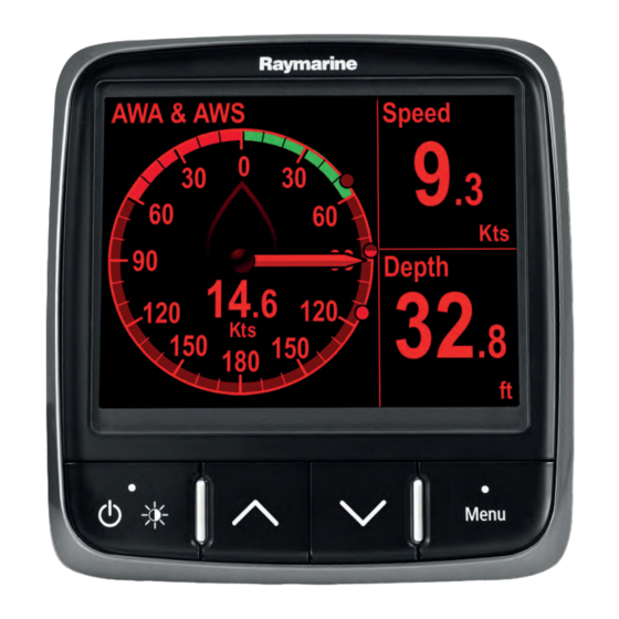
2.2 Product overview The i70 is a multifunctional instrument display with AIS capabilities. In conjunction with a compatible instrument transducer and an iTC-5, the i70 provides a detailed view of environmental, navigational and vessel data. The i70 has the following features: •... -
Page 16: Instrument Controls
Instrument controls Control layout and functions. Item Description LEFT SOFT BUTTON Power, brightness, cancel, back UP ARROW Up navigation, Adjust Up DOWN ARROW Down navigation, Adjust Down RIGHT SOFT BUTTON Menu, select, OK, Save Parts supplied The following parts are supplied with your product. -
Page 17: Compatible Transducers
Description i70 Multifunction instrument display Bezel 400 mm (15.8 in.) SeaTalkng ® Spur Cable Panel seal gasket Suncover Documentation pack SeaTalkng ® Blanking plug 4 x M3x16 pan head PZ screws Unpack the unit carefully to prevent damage. Save the carton and packing in case the unit has to be returned for service. -
Page 18: Software Updates
• Ensure that the unit has a reliable power supply and that the update process is not interrupted. • Damage caused by an incomplete update is not covered by Raymarine warranty. • By downloading the software update package, you agree to these terms. - Page 19 Example: Simple environmental data system Item Description Instrument display (e.g. i70) SeaTalkng ® 12 V dc power supply iTC-5 converter Depth transducer (Analog) Speed / Temperature transducer (Analog) Wind transducer (Analog) Document and product information...
- Page 20 Example: Expanded system without autopilot Item Description AIS receiver / transceiver (AIS350 / AIS650) Instrument display (e.g. i70) Life Tag — Man Over Board (MOB) system SeaTalkng ® GPS/GNSS Receiver (e.g. RS130) SeaTalkng ® 12 V dc power supply Fluxgate compass SeaTalk to SeaTalkng ®...
- Page 21 Example: Expanded system with autopilot Item Description AIS receiver / transceiver (AIS350 / AIS650) Instrument display (e.g. i70) Life Tag — Man Over Board (MOB) system Pilot Controller (e.g. p70 or p70R) Evolution™ Autopilot SeaTalkng ® GPS/GNSS Receiver (e.g. RS130) SeaTalk to SeaTalkng ®...
-
Page 23: Chapter 3 Installation
Chapter 3: Installation Chapter contents • 3.1 Tools required on page 24 • 3.2 Selecting a location on page 24 • 3.3 Product dimensions on page 26 • 3.4 Mounting on page 26 Installation... -
Page 24: Tools Required
Chapter 1 Important information section of this document. EMC installation guidelines Raymarine equipment and accessories conform to the appropriate Electromagnetic Compatibility (EMC) regulations, to minimize electromagnetic interference between equipment and minimize the effect such interference could have on the performance of your system Correct installation is required to ensure that EMC performance is not compromised. -
Page 25: General Location Requirements
• Raymarine specified cables are used. • Cables are not cut or extended, unless doing so is detailed in the installation manual. -
Page 26: Product Dimensions
3.3 Product dimensions Item Description 110 mm (4.33”) 115 mm (4.52”) 14 mm (0.55”) 30 mm (1.18”) 35 mm (1.38”) 90 mm (3.54”) 17 mm (0.67”) 3.4 Mounting The product is designed to be flush mounted. Before mounting the unit, ensure that you have: •... - Page 27 1. Check the selected location for the unit. A clear, flat area with suitable clearance behind the panel, is required. 2. Fix the appropriate cutting template supplied with the product, to the selected location, using masking or self-adhesive tape. 3. Using a suitable hole saw, make a pilot holes in each corner of the cut-out area. 4.
-
Page 28: Front Bezel
Front bezel Removing the front bezel Important: Take care when removing the bezel. Only use a plastic pry tool (not supplied) to lever the bezel, attempting to use another tool may cause damage. 1. Using a plastic pry tool and your fingers pull the bezel away from the unit at the top and on one side, as shown in 2. - Page 29 2. Now pull the bezel away from the unit on the opposite side, as shown in 3. The bezel will now come free from the unit, as shown in 4. Installation...
-
Page 31: Chapter 4 Connections
Chapter 4: Connections Chapter contents • 4.1 General cabling guidance on page 32 • 4.2 Connections overview on page 33 • 4.3 SeaTalkng ® power supply on page 33 • 4.4 Cable ferrite installation on page 39 • 4.5 SeaTalk connection on page 39 •... -
Page 32: General Cabling Guidance
• Unless otherwise stated only use cables supplied by Raymarine. • Where it is necessary to use non-Raymarine cables, ensure that they are of correct quality and gauge for their intended purpose. (e.g.: longer power cable runs may require larger wire gauges to minimize voltage drop along the run). -
Page 33: Connections Overview
4.2 Connections overview Use the following information to help you identify the connections on your product. Connector Connects to: Suitable cables SeaTalkng ® backbone SeaTalkng ® spur cables 2. NMEA 2000 backbone 2. SeaTalkng ® to DeviceNet adaptor cable (A06045) 3. -
Page 34: Seatalkng ® Power Connection Point
Note: • The battery used for starting the vessel’s engine(s) should NOT be used to power the SeaTalkng ® backbone, as this can cause sudden voltage drops when the engines are started. • The ACU-100, ACU-150 or SPX-5 products cannot be used to power the SeaTalkng ® backbone. The SeaTalkng ®... -
Page 35: Seatalkng ® System Loading
• The information provided below is for guidance only, to help protect your product. It covers common vessel power arrangements, but does NOT cover every scenario. If you are unsure how to provide the correct level of protection, please consult an authorized Raymarine dealer or a suitably qualified professional marine electrician. - Page 36 Implementation — connection to distribution panel Waterproof fuse holder with 5 A inline fuse must be fitted (not supplied). 2. SeaTalkng ® power cable. 3. RF Ground connection point for drain wire. • Ideally, the SeaTalkng ® power cable should be connected to a suitable breaker or switch on the vessel's distribution panel or factory-fitted power distribution point.
- Page 37 Important: Observe the recommended fuse / breaker ratings provided in the product’s documentation, however be aware that the suitable fuse / breaker rating is dependent on the number of devices being connected. Implementation — direct connection to battery • SeaTalkng ®Where connection to a power distribution panel is not possible, the power cable may be connected to the vessel's battery..
-
Page 38: Sharing A Breaker
• For power cable extensions, a minimum wire gauge of 16 AWG (1.31 mm ) is recommended. For cable runs longer than 15 meters, you may need to consider a thicker wire gauge (e.g. 14 AWG (2.08 mm ), or 12 AWG (3.31 mm ) ). -
Page 39: Cable Ferrite Installation
Warning: Product grounding Before applying power to this product, ensure it has been correctly grounded, in accordance with the instructions provided. Warning: Positive ground systems Do not connect this unit to a system which has positive grounding. 4.4 Cable ferrite installation Your product is supplied with a suppression ferrite clamp. - Page 40 Example: SeaTalk Evolution system with iTC-5 ACU unit 2 x Instruments Pilot controller Vessel’s 12 V dc power supply EV unit SeaTalk 5–way connector Rudder reference transducer iTC-5 converter Depth transducer Wind transducer Speed transducer...
- Page 41 Example: SeaTalk SPX system with transducer pods Item Description SPX (supplying 12V to SeaTalk network.) 2 x Instruments p70 / p70R Pilot controller Vessel’s 12 V dc power supply SeaTalk 5–way connectors with terminators Transducer pods Rudder reference transducer Fluxgate compass Connections...
-
Page 42: Nmea 2000 Network Connection
Item Description Wind transducer Speed transducer Depth transducer 4.6 NMEA 2000 network connection Your SeaTalk device can be connected to a DeviceNet / NMEA 2000 network. ng® SeaTalk ng® device 2. SeaTalk ng® to DeviceNet adaptor cable (A06045) 3. DeviceNet T-piece 4. -
Page 43: Seatalk Connection
Pilot controller ST60+ Depth instrument ST60+ Speed instrument ST60+ Wind instrument Wind transducer SeaTalk to SeaTalk Adaptor cable Depth transducer Speed transducer Course computer (supplying 12V to SeaTalk network.) For SeaTalk cables and extensions, use Raymarine SeaTalk cable accessories. Connections... -
Page 44: Seatalk Power Protection
The power supply must be protected by a 5 A fuse or a circuit breaker providing equivalent protection. Raymarine recommends that the power is connected to a SeaTalk system in such a way that the current drawn on each side of the power connection point is equal. -
Page 45: Transducer Pod Connection
Transducer pod connection Analog transducer data can be transmitted to the display using legacy transducer pods. Analog transducer (e.g.: speed and temperature transducer) 2. Transducer pod (e.g.: Speed pod) 3. SeaTalkng ® T-Piece connector (A06028) Connect the transducer to the pod, the pod terminals are color-coded, ensure that each wire is connected to the corresponding terminal. - Page 46 Fitting spade connectors to transducer wires Legacy transducer pods use color coded male spade connectors for the transducer connection. 1/8th size female spade connectors are required to be fitted to the transducer wires. If spade terminals need to be fitted follow the steps below: 1.
- Page 47 Connecting transducers to legacy transducer pods Follow the steps below to connect the transducer wires to the transducer pod. Example — Wind pod connection 1. Fit each transducer wire to the relevant color coded connector on the transducer pod. 2. Ensure each spade terminal is pushed fully on to the pod connector. Connections...
-
Page 49: Chapter 5 Maintenance
Chapter 5: Maintenance Chapter contents • 5.1 Service and maintenance on page 50 • 5.2 Routine equipment checks on page 50 • 5.3 Product cleaning on page 50 • 5.4 Cleaning the display case on page 50 • 5.5 Cleaning the display screen on page 50 •... -
Page 50: Service And Maintenance
5.1 Service and maintenance This product contains no user serviceable components. Please refer all maintenance and repair to authorized Raymarine dealers. Unauthorized repair may affect your warranty. 5.2 Routine equipment checks It is recommended that you perform the following routine checks, on a regular basis, to ensure the correct and reliable operation of your equipment: •... -
Page 51: Cleaning The Sun Cover
• use a scouring pad, such as a green Scotch Brite™ pad and a mild household cleaning detergent to clean moderate growth build up. • you may need to use a fine grade wet and dry paper and a mild household cleaning detergent to clean severe build up. -
Page 53: Chapter 6 Troubleshooting
Chapter 6: Troubleshooting Chapter contents • 6.1 Troubleshooting on page 54 • 6.2 Power up troubleshooting on page 54 • 6.3 System data troubleshooting on page 55 • 6.4 Miscellaneous troubleshooting on page 55 Troubleshooting... -
Page 54: Troubleshooting
If after referring to this section you are still having problems with your product, please refer to the Technical support section of this manual for useful links and Raymarine Product Support contact details. -
Page 55: System Data Troubleshooting
• Software corruption. In the unlikely event that the product’s software has become corrupted, try downloading and installing the latest software from the Raymarine website. refer to your Multifunction Display’s operation instructions for details on updating software for SeaTalkng devices. - Page 56 In the unlikely event that the product’s software has become corrupted, try downloading and installing the latest software from the Raymarine website. refer to your Multifunction Display’s operation instructions for details on updating software for SeaTalkng devices. 2. Check the data source for correct operation.
-
Page 57: Chapter 7 Technical Support
Chapter 7: Technical support Chapter contents • 7.1 Raymarine product support and servicing on page 58 • 7.2 Viewing product information on page 59 Technical support... -
Page 58: Raymarine Product Support And Servicing
You can obtain this product information using diagnostic pages of the connected MFD. Servicing and warranty Raymarine offers dedicated service departments for warranty, service, and repairs. Don’t forget to visit the Raymarine website to register your product for extended warranty benefits: http://www.raymarine.co.uk/display/?id=788. United Kingdom (UK), EMEA, and Asia Pacific: •... -
Page 59: Viewing Product Information
• Tel: +47 692 64 600 Denmark (Raymarine subsidiary): • E-Mail: support.dk@raymarine.com • Tel: +45 437 164 64 Russia (Authorized Raymarine distributor): • E-Mail: info@mikstmarine.ru • Tel: +7 495 788 0508 7.2 Viewing product information 1. Press the Menu button. -
Page 61: Chapter 8 Technical Specification
Chapter 8: Technical specification Chapter contents • 8.1 Technical specification on page 62 Technical specification... -
Page 62: Technical Specification
8.1 Technical specification Nominal supply voltage 12 V dc Operating voltage range 9 to 16 V dc Current 132 mA Power consumption 1.6 W LEN (Refer to the SeaTalk reference manual for further information.) Environmental Operating temperature: -25°C to 55°C (-13°F to 131°F) Storage temperature range: -30°C to 70°C (-22°F to 158°F) -
Page 63: Chapter 9 Spares And Accessories
Chapter 9: Spares and accessories Chapter contents • 9.1 Spares and accessories on page 64 • 9.2 Smart transducers on page 64 • 9.3 Instrument Depth, Speed and Temperature (DST) transducers on page 65 • 9.4 Instrument Depth transducers on page 65 •... -
Page 64: Spares And Accessories
The smart transducers listed below are compatible with the following displays: • i70 / i70s • Multifunction displays A22147 — DT800–12 Bronze Thru-Hull A80374 — DT800–12 Plastic Thru-Hull (replaces A22112) A22146 —... -
Page 65: Instrument Depth, Speed And Temperature (Dst) Transducers
The DST transducers listed below are compatible with the following instrument displays: • i40 Depth / i40 Speed / i40 Bidata • i50 Depth / i50 Speed / i50 Tridata • i70 / i70s via iTC-5 converter E26006–PZ — P66 / ST40 Transom mount A26043 — B744V (including fairing block) Thru-hull A26044 —... -
Page 66: Instrument Speed And Temperature Transducers
E26027–PZ — P66 Transom mount 9.5 Instrument Speed and Temperature transducers The speed and temperature transducers listed below are compatible with the following instrument displays: • i40 Speed / i40 Bidata • i50 Speed / i50 Tridata • i70 / i70s via iTC-5 converter... -
Page 67: Instrument Wind Vane Transducer
E26031 — P120 / ST800 Thru-hull M78716 — B120 Thru-hull E25025 — P17 Thru-hull 9.6 Instrument Wind Vane transducer The wind vane transducers listed below are compatible with the following instrument displays: • i60 Wind • i70 / i70s via iTC-5 converter Spares and accessories... -
Page 68: Instrument Rotavecta Transducer
The wind transducers listed below are compatible with the following instrument displays: • i40 Wind • i60 Wind • i70 / i70s via iTC-5 converter Z195 — Rotavecta transducer 9.8 Other transducers When connected using an iTC-5, the transducers listed below are compatible with the your i70 / i70s display:... -
Page 69: Seatalkng ® Cables And Accessories
M81190 — Fluxgate compass M81105 — Rudder Reference 9.9 SeaTalkng ® cables and accessories SeaTalkng ® cables and accessories for use with compatible products. SeaTalkng ® kits SeaTalkng kits enable you to create a simple SeaTalkng backbone. Starter kit (T70134) consists of: 1 x 3 m (9.8 ft) Spur cable (A06040). - Page 70 2 x 5 m (16.4 ft) Backbone cables (A06036). Used to create and extend the SeaTalkng backbone. 1 x 20 m (65.6 ft) Backbone cable (A06037). Used to create and extend the SeaTalkng backbone. 4 x T-piece (A06028). Each T-piece allows connection of one SeaTalkng device. Multiple T-pieces can be ‘daisy chained’...
- Page 71 1 x 2 m (6.6 ft) Power cable (A06049). Used to provide 12 V dc power to the SeaTalkng backbone. 2. 1 x 1 m (3.3 ft) Spur cable (A06039). Used to connect a device to the SeaTalkng backbone. 3. 1 x 0.4 m (1.3 ft) SeaTalk (3 pin) to SeaTalkng adapter cable (A22164). Used to connect SeaTalk devices to the SeaTalkng backbone via the SeaTalk to SeaTalkng converter.
- Page 72 SeaTalkng spur cables: • 0.4 m (1.3 ft) Spur cable (A06038). • 1 m (3.3 ft) Spur cable (A06039). • 3 m (9.8 ft) Spur cable (A06040). • 5 m (16.4 ft) Spur cable (A06041). 2. 0.4 m (1.3 ft) Elbow (right angled) to elbow spur cable (A06042). Used in confined spaces where a straight spur cable will not fit.
- Page 73 2 m (6.6 ft) Power cable (straight) (A06049). 2. 2 m (6.6 ft) Elbow (right angled) power cable (A06070). SeaTalkng ® connectors SeaTalkng connectors are used to connect SeaTalkng devices to the SeaTalkng backbone and to create and extend the backbone. 5-Way connector (A06064).
- Page 74 1 m (3.3 ft) SeaTalk (3 pin) to SeaTalkng converter cable (A22164 / A06073). Can be used to connect a SeaTalk device to a SeaTalkng backbone via the SeaTalk to SeaTalkng converter, or to connect a SeaTalkng product directly to a SeaTalk network. 2.
- Page 75 • 126464 — PGN Transmit and Receive List (Receive / Transmit) • 126996 — Product Information (Receive / Transmit) Raymarine® provides field programmability of the Device and System Instances within PGN 60928 which can be commanded via use of PGN 126208 as required by the latest NMEA 2000 standard.
- Page 76 • 129810 — AIS Class B "CS" Static Report, Part B (Receive) • 130306 — Wind Data (Receive / Transmit) • 130310 — Environmental Parameters (Receive / Transmit) • 130311 — Environmental Parameters (Receive / Transmit) • 130576 — Small Craft Status (Receive) •...
- Page 79 Index Maintenance............50 Accessories SeaTalkng adaptor cables ........73 NMEA 2000............. 75 SeaTalkng backbone cables ....... 72 LEN ..............33 SeaTalkng cables ..........69 NMEA 2000 LEN ............. 34 SeaTalkng connectors ......... 73 SeaTalkng kits .............69 SeaTalkng Power cables ........72 SeaTalkng spur cables .........
- Page 80 Transducer pod ............45 Troubleshooting ............54 Upgrading, See Software updates Warranty ..............58 WEEE Directive............10...
- Page 82 Raymarine Marine House, Cartwright Drive, Fareham, Hampshire. PO15 5RJ. United Kingdom. Tel: +44 (0)1329 246 700 www.raymarine.com a brand by...
Need help?
Do you have a question about the i70 and is the answer not in the manual?
Questions and answers