Raymarine i70 Installation Instructions Manual
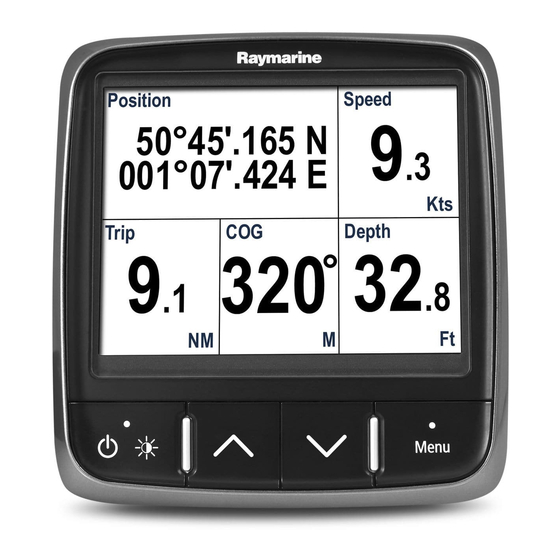
Instrument display
Hide thumbs
Also See for i70:
- Operation instructions manual (104 pages) ,
- Installation & operation instructions (90 pages) ,
- Installation instructions manual (82 pages)

Related Manuals for Raymarine i70


Summary of Contents for Raymarine i70
- Page 1 i7 0 In s t r u m e n t d is p la y Ins ta lla tion ins tructions Docume nt numbe r: 87131-1 Da te : 11-2010...
- Page 3 , SeaTalk and Sportpilot are registered trademarks of Raymarine UK Limited. RayTalk, Seahawk, Smartpilot, Pathfinder and Raymarine are registered trademarks of Raymarine Holdings Limited. FLIR is a registered trademark of FLIR Systems, Inc. and/or its subsidiaries. All other trademarks, trade names, or company names referenced herein are used for identification only and are the property of their respective owners.
-
Page 5: Table Of Contents
2.1 Handbook information ..........12 5.6 Wind calibration ............42 2.2 Installation checklist ..........12 5.7 Trim tab display calibration ........44 2.3 i70 Systems.............. 13 5.8 Setup menu .............. 44 2.4 System protocols ............17 Chapter 6 Troubleshooting........59 2.5 Pack contents ............ - Page 6 Chapter 7 Technical support ........65 7.1 Raymarine customer support ........66 7.2 Viewing product information ........66 Chapter 8 Technical specification......67 8.1 Technical specification..........68 Chapter 9 Options and accessories ....... 69 9.1 SeaTalk cables and accessories ......70 9.2 Converters..............
-
Page 7: Chapter 1 Important Information
IPX6 standard, water intrusion Caution: Use the sun covers and subsequent equipment failure may occur if any Raymarine equipment is subjected to commercial high pressure washing. To protect your product against the damaging effects... -
Page 8: Disclaimers
(as applicable). • The product is supplied from a separate battery from that used Raymarine does not warrant that this product is error-free or that it for engine start. This is important to prevent erratic behavior is compatible with products manufactured by any person or entity and data loss which can occur if the engine start does not have other than Raymarine. -
Page 9: Connections To Other Equipment
Directive requires the recycling of waste electrical and electronic equipment. Whilst the WEEE Directive does not apply to some Raymarine products, we support its policy and ask you to be aware of how to dispose of this product. Important information... - Page 10 Instrument display Installation instructions...
-
Page 11: Chapter 2 Planning The Installation
Chapter contents • 2.1 Handbook information on page 12 • 2.2 Installation checklist on page 12 • 2.3 i70 Systems on page 13 • 2.4 System protocols on page 17 • 2.5 Pack contents on page 18 • 2.6 Tools on page 19... -
Page 12: Handbook Information
2.2 Installation checklist 2.1 Handbook information This handbook contains important information regarding the i70 Installation includes the following activities: instrument display. Installation Task Plan your system i70 Handbooks Obtain all required equipment and tools The i70 Instrument has the following handbooks available:... -
Page 13: I70 Systems
2.3 i70 Systems The i70 display can be connected to a variety of equipment as part of your marine electronics system. Basic SeaTalk system example 12 V D12052-1 Note: The i70 has the capability of connecting to SeaTalk or SeaTalk... - Page 14 Item Description ST70 Instrument display. 2 x i70 Instrument displays. AIS receiver/transceiver SeaTalk GPS receiver SeaTalk T-Piece connector SeaTalk 5–way connectors Transducer pods Wind transducer Speed transducer Depth transducer i70 Instrument display Installation instructions...
- Page 15 Extended SeaTalk system example 12 V SMART D12053-1 Note: The system allows up to 3 instrument displays to be daisy chained as shown in the example above. Planning the installation...
- Page 16 Man Over Board (connected via SeaTalk to SeaTalk converter.) SeaTalk 5–way connectors Multifunction display SeaTalk to SeaTalk converter Transducer pods Fluxgate compass Rudder reference transducer Trim tab control Engine via devicenet spur Wind vane transducer Speed transducer Depth transducer i70 Instrument display Installation instructions...
-
Page 17: System Protocols
2.4 System protocols was specifically intended to allow for a whole network of marine electronics from any manufacturer to communicate on a common bus via standardized message types and formats. Your product can be connected to various products and systems to share information and so improve the functionality of the overall system. -
Page 18: Pack Contents
• Quick reference • Warranty registration card SeaTalk Blanking plug SeaTalk Spur Cable Unpack the display unit carefully to prevent damage. Save the carton and packing in case the unit has to be returned for service. D12054-1 i70 Instrument display Installation instructions... -
Page 19: Tools
2.6 Tools File Adhesive tape Tools required for installation Drill bit of appropriate size* Note: *Drill bit size is dependent on the thickness and type of material that the unit is to be mounted on. D12055-1 Power drill Jig saw Screwdriver Suitable size (10 mm to 30 mm) hole cutter... - Page 20 Instrument display Installation instructions...
-
Page 21: Chapter 3 Cables And Connections
Chapter 3: Cables and connections Chapter contents • 3.1 General cabling guidance on page 22 • 3.2 Connections overview on page 23 • 3.3 SeaTalk connections on page 24 • 3.4 SeaTalk connection on page 25 • 3.5 NMEA2000 connection on page 26 •... -
Page 22: General Cabling Guidance
• Unless otherwise stated use only standard cables of the correct type, supplied by Raymarine. Strain relief • Ensure that any non-Raymarine cables are of the correct quality Ensure adequate strain relief is provided. Protect connectors from and gauge. For example, longer power cable runs may require strain and ensure they will not pull out under extreme sea conditions. -
Page 23: Connections Overview
3.2 Connections overview 3. Fully insert the cable connector. 4. Rotate locking collar clockwise (2 clicks) until it snaps into the Cable connectors are on the rear of the product. LOCKED position. D12056-1 The unit has 2 x SeaTalk connectors. Connecting SeaTalk cables 1. -
Page 24: Seatalk Ng Connections
Required at either end of the backbone. Spur cables Used to connect devices. Devices may be daisy chained or connected directly to the T-pieces SeaTalk 5–way connector Used to branch, split, or make additional connections in SeaTalk networks. D12057-1 i70 Instrument display Installation instructions... -
Page 25: Seatalk Connection
Connections to an existing SeaTalk system must be made using provided from: either a SeaTalk to SeaTalk adaptor cable or a SeaTalk to • Raymarine SPX course computer, or SeaTalk converter (not supplied). • Other separate regulated 12 V supply. -
Page 26: Nmea2000 Connection
Important: You cannot have any 2 terminated backbones connected together, unless you have an isolation gateway Course computer between the two backbones. For SeaTalk cables and extensions, use Raymarine SeaTalk cable Connecting NMEA2000 equipment to the SeaTalk backbone accessories. NM EA 2000... -
Page 27: Transducer Connections
T piece supplied with each pod. Pods must be located no further than 400mm from their corresponding connection points on the backbone. SeaT alk D12060-1 1. i70 instrument display 2. SeaTalk to DeviceNet adaptor cable. 3. DeviceNet backbone. 4. NMEA2000 equipment. - Page 28 Item Description Speed transducer Speed pod SeaTalk T-Piece connector i70 Instrument display Installation instructions...
-
Page 29: Chapter 4 Location And Mounting
Chapter 4: Location and mounting Chapter contents • 4.1 Selecting a location on page 30 • 4.2 Mounting on page 31 Location and mounting... -
Page 30: Selecting A Location
As display contrast, color and night mode performance are all – Ensure that ventilation holes are not obstructed. Allow affected by the viewing angle, Raymarine recommends you adequate separation of equipment. temporarily power up the display when planning the installation, to... -
Page 31: Mounting
4.2 Mounting Unit dimensions I70 dimensions The product is designed to be flush mounted. Before mounting the unit, ensure that you have: • Selected a suitable location. • Identified the cable connections and route that the cable will take. • Detached the front bezel. - Page 32 8. Connect cables to the unit. 9. Slide the unit into place and secure using screws provided. Note: Drill, and tap size and tightening torque is dependent on the material type and thickness the unit is to be mounted on. i70 Instrument display Installation instructions...
-
Page 33: Front Bezel
Front bezel Important: Use care when removing the bezel. Do not use any tools to lever the bezel, doing so may cause damage. Removing the front bezel 1. Using your fingers pull the bezel away from the unit at the top and side, as shown in 2. - Page 34 Instrument display Installation instructions...
-
Page 35: Chapter 5 System Checks
Chapter 5: System checks Chapter contents • 5.1 Initial power on test on page 36 • 5.2 Using the setup wizard on page 37 • 5.3 Transducer calibration on page 37 • 5.4 Depth calibration on page 38 • 5.5 Speed calibration on page 39 •... -
Page 36: Initial Power On Test
If the unit is being switched on for the first time or after a factory reset the setup wizard will be launched. Note: The Raymarine logo is not displayed if the unit is in ’sleep mode’, the unit may appear off but still has power. -
Page 37: Using The Setup Wizard
2. Select Transducer setup and press the CONTINUE button. buttons and then press SELECT. The i70 will search for transducers connected to the system and The welcome screen shall now be displayed and your choices display the results of the search as a list. -
Page 38: Depth Calibration
Note: Incorrect depth offset may lead to vessel running aground. D9343--2 Waterline offset Transducer / Zero offset Keel offset If an offset is not applied, displayed depth readings represent the distance from the transducer to the sea bed. i70 Instrument display Installation instructions... -
Page 39: Speed Calibration
5.5 Speed calibration i. Highlight and select the required calibration speed. ii. Adjust your vessel speed until the SOG is at the desired Speed calibration involves aligning the log speed (Speed Through calibration speed. Water) to the Speed over ground (SOG), under calm tide conditions. iii. - Page 40 Press YES to confirm and delete the selected speed. ii. Press NO to ignore any changes and return to the list of • The current speed value. calibration speeds. • The time it takes to cover the measured distance. Edit. i70 Instrument display Installation instructions...
- Page 41 5. Calculate the actual speed over the measured distance 4. Use the UP and DOWN buttons to match the displayed (distance/time). temperature at the instrument to that measured by the thermometer. 6. If the calculated speed is: 5. Press SAVE to save the setting. •...
-
Page 42: Wind Calibration
• If your rate of turn is too fast during calibration, a slow down message is displayed. If this happens, reduce your rate of 5. Press CONTINUE. turn this can be achieved by slowing down and / or steering in a wider circle. i70 Instrument display Installation instructions... - Page 43 6. Now steer your vessel directly into the wind and then press 4. Press SELECT to save the settings and return to the Wind page. CONTINUE. D12068-1 7. If required use the UP and DOWN buttons to manually adjust the vane offset. 8.
-
Page 44: Trim Tab Display Calibration
5.8 Setup menu The setup menu provides a range of tools and settings to configure Calibrating trim tabs display position the instrument display. The i70 can display, on screen the position of your vessel’s trim Menu item Description Options tabs, in order for this function to show correct position the trim tab... - Page 45 Menu item Description Options Simulator Enables or disables • On simulator mode, • Off which allows you to practice operating your instrument display without any data from any other external unit. Factory reset Delete user settings and • Yes Restore unit to factory •...
- Page 46 • speed settings are determined by the calibration at each of the speed points shown under speed points stored either in the transducer or the calibration. interface unit. • Calibrate water temperature Calibrate water temperature: • xxx ºC or ºF i70 Instrument display Installation instructions...
- Page 47 Menu item Description Options Wind Enables setup and calibration of wind transducers Details displays information about the installed and provides the following options: transducer, Serial No. and Software version etc. Calibrate vane- follow the on screen instructions to • Wind detail calibrate the wind vane.
- Page 48 Provides on screen instruction on how to setup and Trim tabs up calibrate trim tab display position: • Click CONTINUE to confirm tabs fully up. • Trim tabs up • Click CONTINUE to confirm tabs fully down. • Trim tabs down i70 Instrument display Installation instructions...
- Page 49 User preference menu The User preference menu enables users to customize user settings as detailed in the table below: Menu item Description Options Time & date These options enable you to customize the date Date format: and time format to your requirements. You can •...
- Page 50 Heading: • Mag — magnetic. • True Pressure • PSI — pounds per square inch. • Bar — bar. • kPa — Kilo pascals. Volume: • UK Gallons • US Gallons • ltr — litre. i70 Instrument display Installation instructions...
- Page 51 Menu item Description Options Language Determines the language that will be used for all • Chinese on-screen text, labels, menus and options. • Croatian • Danish • Dutch • English — UK • English — US • Finnish • French •...
- Page 52 Number of fuel tanks • 1 — 5 Variation Enables you to turn on and off magnetic variation, Variation mode: specify slave source or adjust manually. • On • Variation mode • Off • Variation range • Slave i70 Instrument display Installation instructions...
- Page 53 Menu item Description Options Variation range: • -30º — +30º System checks...
-
Page 54: System Setup Menu
Brightness / color group This enables you to synchronize the displays Sync brightness / color brightness and color to be the same as the other units • This display in the same network group. • This group i70 Instrument display Installation instructions... - Page 55 Menu item Description Options Multiple data sources This allows you to view and select preferred data Select data source sources. • GPS position • Select data source • Heading • Data source found • Depth • Data source details • Speed •...
- Page 56 • Run time • Deviation (If available) About system Allows you to view information about products on the • Model number system you are using: • Serial number • Software version • Hardware version • Volts i70 Instrument display Installation instructions...
- Page 57 Menu item Description Options Key beep Enables you to turn on and off the audible beeps • On when keys are pressed • Off Self test The product has a built in self test which can help • Memory test to diagnose faults.
- Page 58 Instrument display Installation instructions...
-
Page 59: Chapter 6 Troubleshooting
Chapter 6: Troubleshooting Chapter contents • 6.1 Troubleshooting on page 60 • 6.2 Power up troubleshooting on page 61 • 6.3 System data troubleshooting on page 62 • 6.4 Miscellaneous troubleshooting on page 63 Troubleshooting... -
Page 60: Troubleshooting
All Raymarine products are, prior to packing and shipping, subjected to comprehensive test and quality assurance programs. However, if you experience problems with the operation of your product this section will help you to diagnose and correct problems in order to restore normal operation. -
Page 61: Power Up Troubleshooting
6.2 Power up troubleshooting Problems at power up and their possible causes and solutions are described here. Problem Possible causes Possible solutions Power supply problem. The system (or part of it) does not start up. Check relevant fuses and breakers. Check that the power supply cable is sound and that all connections are tight and free from corrosion. -
Page 62: System Data Troubleshooting
Check that all required equipment is connected to the SeaTalk switch. from some but not all displays. Check the status of the SeaTalk Switch. Check that SeaTalk cables are free from damage. Software mismatch between equipment Contact Raymarine technical support may prevent communication. i70 Instrument display Installation instructions... -
Page 63: Miscellaneous Troubleshooting
Ensure that the front bezel is fitted correctly and that all buttons are free to operate correctly. Software mismatch on system (upgrade Go to www.raymarine.com and click on support for the latest software required). downloads. Corrupt data / other unknown issue. - Page 64 Instrument display Installation instructions...
-
Page 65: Chapter 7 Technical Support
Chapter 7: Technical support Chapter contents • 7.1 Raymarine customer support on page 66 • 7.2 Viewing product information on page 66 Technical support... -
Page 66: Raymarine Customer Support
Raymarine provides a comprehensive customer support service. 1. From the main menu scroll to Set Up and press the SELECT key. You can contact customer support through the Raymarine website, 2. From the Set Up menu scroll to Diagnostics and press the telephone and email. -
Page 67: Chapter 8 Technical Specification
Chapter 8: Technical specification Chapter contents • 8.1 Technical specification on page 68 Technical specification... -
Page 68: Technical Specification
TFT LCD display, 16bit color (64k colors) Resolution: 320x240 Brightness: 700 cd/m2 Data connections 2 x SeaTalk ports (fulling compliant with NMEA2000 & SeaTalk specifications). Conformance • Europe 2004/108/EC • Australia and New Zealand C-Tick, compliance level 2 i70 Instrument display Installation instructions... -
Page 69: Chapter 9 Options And Accessories
Chapter 9: Options and accessories Chapter contents • 9.1 SeaTalk cables and accessories on page 70 • 9.2 Converters on page 71 • 9.3 SeaTalk accessories on page 71 • 9.4 Spares and accessories on page 72 Options and accessories... -
Page 70: Seatalk Ng Cables And Accessories
SeaTalk 5 m (16.4 ft) A80001 SeaTalk Inline spur terminator SeaTalk 0.4 m (1.3 ft) A06033 SeaTalk Blanking plug A06032 backbone SeaTalk 1 m (3.3 ft) A06034 backbone SeaTalk 3 m (9.8 ft) A06035 backbone i70 Instrument display Installation instructions... -
Page 71: Converters
9.2 Converters 9.3 SeaTalk accessories SeaTalk cables and accessories for use with compatible products. Part number Description Description Part No Notes E22158 SeaTalk to SeaTalk Converter NMEA / SeaTalk E85001 converter 3 m (9.8 ft) SeaTalk D285 extension cable 5 m (16.4 ft) SeaTalk D286 extension cable 9 m (29.5 ft) SeaTalk... -
Page 72: Spares And Accessories
9.4 Spares and accessories Part number Description R22168 Spare bezel R22169 Sun cover i70 Instrument display Installation instructions... - Page 73 Owner notes:...
- Page 74 Owner notes:...
- Page 76 www.ra ym a rin e .c o m...
Need help?
Do you have a question about the i70 and is the answer not in the manual?
Questions and answers