Raymarine i60 wind Installation And Operation Instructions Manual
Hide thumbs
Also See for i60 wind:
- Manual (104 pages) ,
- Installation & operation instructions (76 pages) ,
- Installation and operation instructions manual (62 pages)

Related Manuals for Raymarine i60 wind


Summary of Contents for Raymarine i60 wind
- Page 1 W ind i60 CH W ind Display T rue/App T ack Installation and operation instructions Date: 06-2014 Document number: 81342-2-EN © 2014 Raymarine UK Limited...
- Page 3 Trademark and patents notice Raymarine, Tacktick, Clear Pulse, Truzoom, HSB, SeaTalk, SeaTalk , SeaTalk , Micronet, Raytech, Gear Up, Marine Shield, Seahawk, Autohelm, Automagic, and Visionality are registered or claimed trademarks of Raymarine Belgium. FLIR, DownVision, SideVision, Dragonfly, Instalert, Infrared Everywhere, and The World’s Sixth Sense are registered or claimed trademarks of FLIR Systems, Inc.
-
Page 5: Table Of Contents
6.2 Power ..............34 6.3 Data master............35 Chapter 7 Calibration .......... 37 7.1 User calibration............ 38 7.2 Intermediate calibration ........39 7.3 Dealer calibration ..........39 Chapter 8 Using your display......43 8.1 Pages ..............44 8.2 i60 Wind operation ..........44... -
Page 7: Chapter 1 Important Information
Disclaimer Do not connect this unit to a system which has positive grounding. Raymarine does not warrant that this product is error-free or that it is compatible with products Caution: Power supply protection manufactured by any person or entity other than Raymarine. -
Page 8: Suppression Ferrites
Declaration of conformity between different items of electrical equipment, to provide the best conditions for EMC performance Raymarine UK Ltd. declares that this product is throughout the installation compliant with the essential requirements of EMC directive 2004/108/EC. -
Page 9: Technical Accuracy
To the best of our knowledge, the information in this document was correct at the time it was produced. However, Raymarine cannot accept liability for any inaccuracies or omissions it may contain. In addition, our policy of continuous product improvement may change specifications without notice. -
Page 11: Chapter 2 Handbook Information
Chapter 2: Handbook information Chapter contents • 2.1 Document information on page 12 • 2.2 Parts supplied on page 13 • 2.3 i60 Product overview on page 13 Handbook information... -
Page 12: Document Information
Your product may differ slightly from that shown This document contains important information in the illustrations in this document, depending on related to the installation of your Raymarine product. product variant and date of manufacture. The document includes information to help you: All images are provided for illustration purposes only. -
Page 13: Parts Supplied
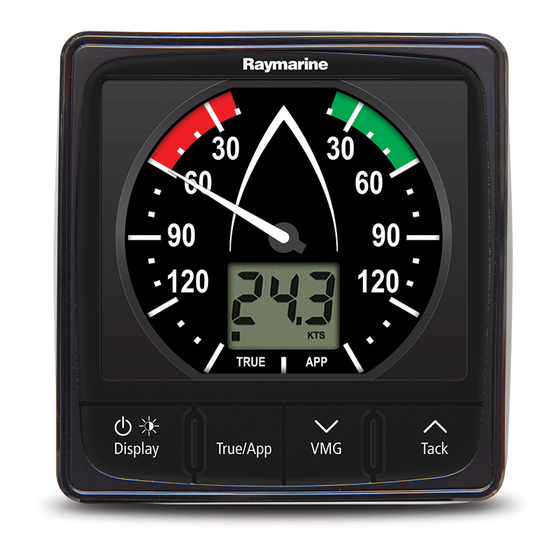
T ack Dis play T rue/App T ack D12549-2 1. i60 Wind — The i60 Wind instrument provides a 360º wind direction scale and can be used as D12388-1 a stand alone unit or as part of a SeaTalk or SeaTalk network. -
Page 15: Chapter 3 Planning The Installation
Chapter 3: Planning the installation Chapter contents • 3.1 Installation checklist on page 16 • 3.2 Compatible transducers on page 16 • 3.3 Typical systems on page 17 • 3.4 System protocols on page 19 • 3.5 Tools required on page 19 •... -
Page 16: Installation Checklist
Instrument Wind Vane transducer Installation Task The wind vane transducers listed below are compatible with the following instrument displays: Plan your system. • i60 Wind Obtain all required equipment and tools. • i70 via iTC-5 converter Site all equipment. Part Route all cables. -
Page 17: Typical Systems
Wind instrument Raymarine wind vane transducer Raymarine multifunction display 12 / 24 V dc power supply Raymarine course computer (providing 12 V dc power supply to the SeaTalk network.) i50 Speed instrument i50 Depth instrument Speed transducer... - Page 18 D12374-1 SeaTalk pilot controller SeaTalk instrument displays Fluxgate compass Rudder reference Raymarine course computer (providing 12 V dc power supply to SeaTalk network.) 12 / 24 V dc power supply Raymarine AIS transceiver Raymarine SeaTalk Man over board SeaTalk to SeaTalk...
-
Page 19: System Protocols
3.4 System protocols 3.5 Tools required Your product can be connected to various products Tools required for installation and systems to share information and so improve the functionality of the overall system. These connections may be made using a number of different protocols. -
Page 20: Selecting A Display Location
Viewing angle considerations As display contrast, color and night mode performance are all affected by the viewing angle, Raymarine recommends you temporarily power up the display when planning the installation, to enable you to best judge which location gives the optimum... -
Page 21: Product Dimensions
3.7 Product dimensions 3.8 Wind vane transducer / rotavecta location requirements When selecting a location for your wind transducer it is important to consider a number of factors. The transducer's location must: • Allow reasonable access for installation and servicing. •... -
Page 23: Chapter 4 Cables And Connections
Chapter 4: Cables and connections Chapter contents • 4.1 General cabling guidance on page 24 • 4.2 Power connection on page 24 • 4.3 SeaTalk connections on page 25 • 4.4 Transducer connections on page 26 • 4.5 iTC-5 connection on page 26 •... -
Page 24: General Cabling Guidance
Raymarine. • By a battery via the distribution panel, or • Ensure that any non-Raymarine cables are of the • From a Raymarine course computer, via a SeaTalk correct quality and gauge. For example, longer or a SeaTalk system. -
Page 25: Seatalk Ng Connections
The power supply must be protected by a 5 A fuse or a circuit breaker providing equivalent protection. Raymarine recommends that the power is connected to a SeaTalk system in such a way that the current drawn on each side of the power connection point is equal. -
Page 26: Transducer Connections
4.4 Transducer connections 4.5 iTC-5 connection Transducer connections only apply to the i60 Wind Transducers can be connected to a SeaTalk instrument, the i60 Close hauled wind does not network using Raymarine's Instrument transducer include transducer connections as it is a repeater converter (iTC-5) and an i70 instrument, the data display. -
Page 27: Seatalk Connection
The power supply must be protected by a 5 A fuse or a circuit breaker providing equivalent protection. Raymarine recommends that the power is connected to a SeaTalk system in such a way that the current drawn on each side of the power connection point is equal. -
Page 28: Nmea2000 Connection
4.7 NMEA2000 connection You can either: • Use your SeaTalk backbone and connect each NMEA2000 device on a spur, OR • connect the instrument display on a spur into an existing NMEA2000 backbone. Important: You cannot have any 2 terminated backbones connected together, unless you have an isolation gateway between the two backbones. -
Page 29: Chapter 5 Mounting
Chapter 5: Mounting Chapter contents • 5.1 Mounting on page 30 • 5.2 Front bezel on page 31 Mounting... -
Page 30: Mounting
5.1 Mounting Note: The supplied gasket provides a seal between the unit and a suitably flat and stiff Pre-mounting check mounting surface or binnacle. The gasket should be used in all installations. It may also be The product is designed to be surface mounted. necessary to use a marine-grade sealant if the Before mounting the unit, ensure you have: mounting surface or binnacle is not entirely flat and... -
Page 31: Front Bezel
5.2 Front bezel Removing the front bezel D12372-1 Note: Use care when removing the bezel. Do not use any tools to lever the bezel, doing so may cause damage. 1. Using your fingers pull the bezel away from the unit at the top and side, as shown in 2. The bezel will start to come away from the unit at the top and side. -
Page 33: Chapter 6 Getting Started
Chapter 6: Getting started Chapter contents • 6.1 Controls on page 34 • 6.2 Power on page 34 • 6.3 Data master on page 35 Getting started... -
Page 34: Controls
6.1 Controls 6.2 Power Powering on the unit With power to the unit turned on but the unit switched off: 1. Press and hold the Power button until the unit powers on and data is displayed (approximately 2 seconds). Note: When power to the unit is turned on the unit will switch on automatically. -
Page 35: Data Master
6.3 Data master Where a system contains more than one unit capable of displaying a data type, the unit physically connected to the transducer must be set as the data master and any other units set as a repeater. Checking the software version and instrument status You can check the instrument display’s software version and status by following the steps below. -
Page 37: Chapter 7 Calibration
Chapter 7: Calibration Chapter contents • 7.1 User calibration on page 38 • 7.2 Intermediate calibration on page 39 • 7.3 Dealer calibration on page 39 Calibration... -
Page 38: User Calibration
VMG and The i60 CH instrument display is a repeater display Tack buttons. and as such does not require calibration, the steps below apply to the calibration of the i60 Wind Ta ck instrument only. User calibration options include: •... -
Page 39: Intermediate Calibration
7.2 Intermediate calibration 7.3 Dealer calibration The dealer calibration procedures include: Intermediate calibration allows you to: • User calibration menu access On (default) and Off. • Check instrument software version • Display Response for wind angle readings — • * Check the instrument status (either master or Dictates the rate at which the instrument display repeater) responds to changes in wind angle data. - Page 40 Setting the wind speed Calibration Factor 1. Press the Display button until the Wind Angle Response page is displayed (1 press from the If you find that your wind speed readings deviate from User Calibration Access Menu page). a referenced wind speed source then a Calibration Factor can be applied to reduce the deviation.
- Page 41 Note: To exit the dealer calibration pages at any time press and hold the Display and True / App buttons at the same time for approximately 2 seconds. Calibration...
-
Page 43: Chapter 8 Using Your Display
Chapter 8: Using your display Chapter contents • 8.1 Pages on page 44 • 8.2 i60 Wind operation on page 44 • 8.3 Illumination on page 46 Using your display... -
Page 44: Pages
8.1 Pages 8.2 i60 Wind operation When connected to a relevant rotavecta or wind The pages available depend on the display variant vane transducer the i60 provides: and are shown in the table below: • True and apparent wind direction and speed. Wind... - Page 45 1. Use the Display button to cycle through the 2. Wind angle (specified in degrees) available pages. True Wind Angle (TWA) — The angle between 2. Press and hold the Tack button for 3 seconds the TWD and the center line of the vessel. to reset the maximum wind speed to the current Apparent Wind Angle (AWA) —...
-
Page 46: Illumination
8.3 Illumination When connected on a SeaTalk network the unit can participate in group illumination and be assigned to a group of units which will share their backlighting Adjusting the backlight level levels. Available groups are as follows: The backlighting can be adjusted using the power button. -
Page 47: Chapter 9 Alarms
Chapter 9: Alarms Chapter contents • 9.1 Alarms on page 48 Alarms... -
Page 48: Alarms
1. Press any button to silence an active alarm. Instrument alarms Enabling / Disabling alarms Alarms available on the i60 Wind are listed below. Alarms can be enabled or disabled at any time. • High true wind speed With the relevant alarm page displayed: •... -
Page 49: Chapter 10 Maintaining Your Display
Chapter 10: Maintaining your display Chapter contents • 10.1 Service and maintenance on page 50 • 10.2 Condensation on page 50 • 10.3 Routine equipment checks on page 51 • 10.4 Cleaning on page 51 • 10.5 Cleaning the display case on page 52 •... -
Page 50: Service And Maintenance
Certain atmospheric conditions may cause a small components. Please refer all maintenance amount of condensation to form on the unit's window. and repair to authorized Raymarine dealers. This will not damage the unit and will clear after the Unauthorized repair may affect your warranty. -
Page 51: Routine Equipment Checks
10.3 Routine equipment checks 10.4 Cleaning Raymarine strongly recommends that you complete Best cleaning practices. a number of routine checks to ensure the correct and When cleaning this product: reliable operation of your equipment. • Do NOT wipe the display screen with a dry cloth, Complete the following checks on a regular basis: as this could scratch the screen coating. -
Page 52: Cleaning The Display Case
10.5 Cleaning the display case 10.6 Cleaning the display screen The display unit is a sealed unit and does not require A coating is applied to the display screen. This regular cleaning. If it is necessary to clean the unit, makes it water repellent, and prevents glare. -
Page 53: Chapter 11 Troubleshooting
Chapter 11: Troubleshooting Chapter contents • 11.1 Troubleshooting on page 54 • 11.2 Instrument troubleshooting on page 55 • 11.3 Power up troubleshooting on page 56 • 11.4 Miscellaneous troubleshooting on page 57 Troubleshooting... -
Page 54: Troubleshooting
All Raymarine products are, prior to packing and shipping, subjected to comprehensive test and quality assurance programs. However, if you experience problems with the operation of your... -
Page 55: Instrument Troubleshooting
11.2 Instrument troubleshooting Fault Cause Action Blank display. No power supply. • Check fuse / circuit breaker. • Check power supply. • Check SeaTalk / SeaTalk cabling and connector security. SeaTalk / SeaTalk information not being SeaTalk / SeaTalk cabling or connector •... -
Page 56: Power Up Troubleshooting
11.3 Power up troubleshooting Problems at power up and their possible causes and solutions are described here. Problem Possible causes Possible solutions The system (or part of it) does Power supply problem. Check relevant fuses and breakers. not start up. Check that the power supply cable is sound and that all connections are tight and free from corrosion. -
Page 57: Miscellaneous Troubleshooting
Check that the power source is of the correct voltage and erratic behavior. sufficient current. Software mismatch on system Go to www.raymarine.com and click on support for the (upgrade required). latest software downloads. Corrupt data / other unknown Perform a factory reset. -
Page 59: Chapter 12 Technical Support
Chapter 12: Technical support Chapter contents • 12.1 Raymarine customer support on page 60 • 12.2 Checking the software version on page 60 Technical support... -
Page 60: Raymarine Customer Support
Follow the steps below to identify the software support service. You can contact customer support version of your unit. through the Raymarine website, telephone and During normal operation: e-mail. If you are unable to resolve a problem, please 1. Press and hold the Display (Power) and True / use any of these facilities to obtain additional help. -
Page 61: Chapter 13 Technical Specification
Chapter 13: Technical specification Chapter contents • 13.1 Technical specification on page 62 Technical specification... -
Page 62: Technical Specification
13.1 Technical specification Nominal supply voltage 12 V dc Operating voltage range 10 V dc to 16 V dc Power consumption • < 1 W Typical (Display only) • 2.4 W Maximum (Transducer connected) Current • 45 to 65 mA Typical (Display only) •... -
Page 63: Chapter 14 Spares And Accessories
Chapter 14: Spares and accessories Chapter contents • 14.1 Spares on page 64 • 14.2 SeaTalk cables and accessories on page 64 • 14.3 Converters on page 65 Spares and accessories... -
Page 64: Spares
14.1 Spares 14.2 SeaTalk cables and accessories SeaTalk cables and accessories for use with The table below lists the spare parts available for compatible products. i60 instrument displays Description Part No Notes Description Part number Note SeaTalk starter kit T70134 Includes: i50 / i60 / i70 front R22168... -
Page 65: Converters
14.3 Converters Description Part No Notes SeaTalk Power A06049 Part number Description cable E22158 SeaTalk to SeaTalk SeaTalk A06031 Converter Terminator SeaTalk T-piece A06028 Provides 1 x spur connection SeaTalk 5–way A06064 Provides 3 x spur connector connections SeaTalk A06030 backbone extender SeaTalk to E22158... -
Page 67: Appendix A Nmea 2000 Sentences
Appendix A NMEA 2000 sentences The i60 instrument range supports the following NMEA 2000 Parameter Group Number (PGN) sentences. PG name i60 Wind Transmit i60 Wind Receive ● ISO Acknowledgement 59392 ● ISO Request 59904 ● ● ISO Address claim 60928 ●... - Page 70 www.ra ym a rin e .c o m...
Need help?
Do you have a question about the i60 wind and is the answer not in the manual?
Questions and answers