Raymarine i70 Installation & Operation Instructions
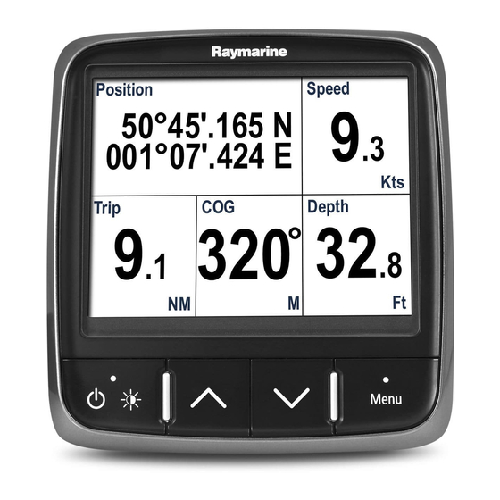
Instrument display
Hide thumbs
Also See for i70:
- Operation instructions manual (104 pages) ,
- Installation instructions manual (82 pages) ,
- User manual (69 pages)
Table of Contents
Advertisement
Quick Links
Advertisement
Table of Contents
Troubleshooting

Related Manuals for Raymarine i70


Summary of Contents for Raymarine i70
- Page 1 Instrument INSTALLATION & OPERATION INSTRUCTIONS...
- Page 2 Trademark and patents notice Raymarine, Tacktick, Clear Pulse, Truzoom, HSB, SeaTalk, SeaTalk , SeaTalk , Micronet, Raytech, Gear Up, Marine Shield, Seahawk, Autohelm, Automagic, and Visionality are registered or claimed trademarks of Raymarine Belgium. FLIR, DownVision, SideVision, Dragonfly, Quantum, Instalert, Infrared Everywhere, and The World’s Sixth Sense are registered or claimed trademarks of FLIR Systems, Inc.
-
Page 3: Table Of Contents
Contents Chapter 1 Important information..... 9 Strain relief ..........26 TFT Displays ..........9 Cable shielding........26 Water ingress ..........9 4.2 Connections overview ....... 26 Disclaimer..........10 Connecting SeaTalkng® cables ....26 EMC installation guidelines ..... 10 SeaTalkng® product loading ....26 Suppression ferrites ........ - Page 4 15.5 Performing a Factory Reset .... 94 Resetting accumulative data ....55 Chapter 16 Technical support ....95 Chapter 9 Data (Quick View)....57 16.1 Raymarine product support and 9.1 Data items ......... 58 servicing ..........96 9.2 Viewing Data (Quick View)....60 16.2 Viewing product information ....
- Page 5 18.2 Smart transducers ......102 18.3 Instrument Depth, Speed and Temperature (DST) transducers.... 103 18.4 Instrument Depth transducers..........104 18.5 Instrument Speed and Temperature transducers ...... 104 18.6 Instrument Wind Vane transducer ..........105 18.7 Instrument Rotavecta transducer ..........105 18.8 Other transducers......
-
Page 6: Chapter 1 Important Information
IPX standard (refer to the specification section for voltage rating. product’s Technical Specification), water intrusion and subsequent equipment failure may occur if the product is subjected to commercial high-pressure washing. Raymarine will not warrant products subjected to high-pressure washing. Important information... -
Page 7: Disclaimer
Disclaimer separately to the cables (i.e. not pre-fitted), you must fit the supplied ferrites, using the supplied Raymarine does not warrant that this product is instructions. error-free or that it is compatible with products • If a ferrite has to be removed for any purpose (e.g. -
Page 8: Document Information
Description Part number i70 Installation and operation instructions 81357 Installation and operation instructions for the i70 unit and connection to a wider system of marine electronics. i70 Mounting template 87130 Mounting diagram for surface mounting a i70 unit. Additional documentation... -
Page 9: Chapter 3 Planning The Installation
Chapter 3: Planning the installation Chapter contents • 3.1 Installation checklist on page 16 • 3.2 Parts supplied on page 16 • 3.3 Software updates on page 17 • 3.4 Tools on page 17 • 3.5 Typical systems on page 18 •... -
Page 10: Installation Checklist
The diagram should include: • Location of all components. • Connectors, cable types, routes and lengths. Description i70 Multifunction instrument display Bezel 400 mm (15.8 in.) SeaTalkng® Spur Cable Panel seal gasket Suncover Documentation pack SeaTalkng®... -
Page 11: Software Updates
3.3 Software updates 3.4 Tools Tools required for installation The software running on the product can be updated. • Raymarine periodically releases software updates to improve product performance and add new features. • You can update the software for your product using a connected and compatible multifunction display. -
Page 12: Typical Systems
The following illustrations show the products that can be connected in a typical system. Example: Simple environmental data system Item Description Instrument display (e.g. i70) SeaTalkng® 12 V dc power supply iTC-5 converter Depth transducer (Analog) Speed / Temperature transducer... - Page 13 Example: Expanded system without autopilot Item Description AIS receiver / transceiver (AIS350 / AIS650) Instrument display (e.g. i70) Life Tag — Man Over Board (MOB) system SeaTalkng® GPS/GNSS Receiver (e.g. RS130) SeaTalkng® 12 V dc power supply Fluxgate compass SeaTalk to SeaTalkng® converter...
- Page 14 Example: Expanded system with autopilot Item Description AIS receiver / transceiver (AIS350 / AIS650) Instrument display (e.g. i70) Life Tag — Man Over Board (MOB) system Pilot Controller (e.g. p70 or p70R) Evolution™ Autopilot SeaTalkng® GPS/GNSS Receiver (e.g. RS130) SeaTalk to SeaTalkng® converter...
-
Page 15: System Protocols
3.6 System protocols 3.7 Warnings and cautions Your product can be connected to various products Important: Before proceeding, ensure that you and systems to share information and so improve have read and understood the warnings and the functionality of the overall system. cautions provided in the Chapter 1 Important information... -
Page 16: General Location Requirements
Important considerations when choosing a suitable performance are all affected by the viewing angle, location for your product. Raymarine recommends you temporarily power up This product is suitable for mounting above or below the display when planning the installation, to enable decks. -
Page 17: Product Dimensions
3.9 Product dimensions Item Description 110 mm (4.33”) 115 mm (4.52”) 14 mm (0.55”) 30 mm (1.18”) 35 mm (1.38”) 90 mm (3.54”) 17 mm (0.67”) Planning the installation... -
Page 18: Chapter 4 Cables And Connections
Chapter 4: Cables and connections Chapter contents • 4.1 General cabling guidance on page 26 • 4.2 Connections overview on page 26 • 4.3 SeaTalkng® power supply on page 27 • 4.4 Cable ferrite installation on page 29 • 4.5 SeaTalk connection on page 30 •... -
Page 19: General Cabling Guidance
• Unless otherwise stated use only standard cables backbone spur cables of the correct type, supplied by Raymarine. NMEA 2000 SeaTalkng® • Ensure that any non-Raymarine cables are of the backbone to DeviceNet correct quality and gauge. For example, longer adaptor SeaTalk... -
Page 20: Seatalkng® Power Supply
In the example above the system has an overall LEN please consult an authorized Raymarine dealer or of 10, so the optimum connection point would be to a suitably qualified professional marine electrician. -
Page 21: Sharing A Breaker
(12 V dc) is available at the SeaTalkng® backbone’s power connection. More information Raymarine recommends that best practice is observed in all vessel electrical installations, as detailed in the following standards: • BMEA Code of Practice for Electrical and Electronic Installations in Boats •... -
Page 22: Cable Ferrite Installation
4.4 Cable ferrite installation Warning: Positive ground systems Your product is supplied with a cable ferrite. To ensure EMC Compliance, the supplied ferrite must Do not connect this unit to a system which be fitted to the cable according to the following has positive grounding. -
Page 23: Seatalk Ng Connection
4.5 SeaTalk connection Example: SeaTalk SPX system with transducer pods Note: In the example below, if an ACU-100 was used, the SeaTalk network would require a dedicated 12 V dc power supply because the ACU-100 does not supply power to the SeaTalk network. -
Page 24: Nmea 2000 Network
Depth transducer Speed transducer Course computer (supplying 12V to SeaTalk network.) For SeaTalk cables and extensions, use Raymarine SeaTalk cable accessories. SeaTalk power protection The power supply must be protected by a 5 A fuse or a circuit breaker providing equivalent protection. -
Page 25: Transducer Connections
4.8 Transducer connections iTC-5 connection For details on connecting an iTC-5 to the SeaTalk ng® backbone and connecting transducers to the iTC-5, refer to the documentation provided with your iTC-5. Transducer pod connection Transducer pods are available for wind, depth and speed transducers. -
Page 26: Chapter 5 Mounting
5.1 Mounting Front bezel Removing the front bezel The product is designed to be flush mounted. Before mounting the unit, ensure that you have: • Selected a suitable location. • Identified the cable connections and route that the cable will take. •... -
Page 27: Chapter 6 Getting Started
Chapter 6: Getting started Chapter contents • 6.1 Instrument controls on page 36 • 6.2 Power on page 36 • 6.3 Completing the startup wizard on page 37 • 6.4 Display settings on page 37 • 6.5 Multiple data sources (MDS) overview on page 39 •... -
Page 28: Instrument Controls
6.1 Instrument controls 6.2 Power Control layout and functions. Powering on the unit The unit will automatically turn on with the system, unless it has previously been powered off using the Power button. With the unit powered off: 1. Press and hold the Power button until the screen turns on (approximately 2 seconds). -
Page 29: Completing The Startup Wizard
6.3 Completing the startup wizard 6.4 Display settings When you power-up the unit for the first time or after Adjusting the unit’s brightness a system reset the Startup Wizard is displayed. To adjust the unit’s LCD brightness level, when it The setup wizard guides your through the following is not part of a Shared Brightness group follow the basic configuration settings:... -
Page 30: Display Response
• all the displays in that group to be synchronized. 1. Select a color scheme from the list Assigning A Network Group • Day 1 To enable the Shared Brightness and Color, unit’s • Day 2 must be assigned to the same network group. •... -
Page 31: Multiple Data Sources (Mds) Overview
6.5 Multiple data sources (MDS) overview When a system includes multiple instances of a data source the preferred data source is selected automatically. The systems preferred source may not be your preferred source, or if you are experiencing a data conflict you can manually select your preferred data source. -
Page 32: Quick Options Menu
6.6 Quick Options menu The Quick Options menu (Menu > Quick Options) is a dynamic menu that displays menu items relative to the data displayed on the current Favorite page or Quick View page being viewed. Quick options menu items Depending on the page being displayed different quick options are available as follows: Page displayed... -
Page 33: Chapter 7 Transducer Calibration
Chapter 7: Transducer calibration Chapter contents • 7.1 Transducer types on page 42 • 7.2 Depth calibration on page 42 • 7.3 Speed calibration on page 43 • 7.4 Wind calibration on page 48 • 7.5 Rudder reference calibration on page 50 •... -
Page 34: Transducer Types
7.1 Transducer types 7.2 Depth calibration The transducers listed in the table below can be Depth Offset calibrated using the display. Depths are measured from the transducer to the Transducer type Connection bottom, you can apply an offset value to the depth data, so that the displayed depth reading represents Depth transducers connected via iTC-5 or Depth... -
Page 35: Speed Calibration
7.3 Speed calibration 9. Select the location that you want depth measurements to be taken from. Speed transducer calibration is required as After selection the Depth Offset page is displayed. transducer performance is affected by a number of If you have selected Waterline or Keel a Depth variables such as transducer location, shape of the Offset must be applied. -
Page 36: Point Speed Calibration
1 Point Speed Calibration then a Speed Run Calibration should be performed. Refer to the Performing a Speed Run Calibration For most installations a 1 Point Speed Calibration is using SOG section for details. all that is required. Prerequisites: Nautical measured mile markers •... -
Page 37: Performing A Speed Run Calibration Using Sog
Measuring a nautical mile 5. Select the device that the transducer(s) you are calibrating are connected to. A list of available transducer data is displayed, 6. * Select Speed. Important: * Step only applicable to iTC-5. 7. Select Speed Calibration. 8. - Page 38 • Reset the Calibration Table to factory defaults The Check Speed page can also be accessed from the Edit calibration options menu: Advanced > Viewing the calibration Table Adjust cal table > Start > Options > Check speed. Calibration points are stored in the Calibration Table. Manually working out a Calibration Factor From a favorite page: New Calibration Factors can be worked out manually...
- Page 39 1. Select the device that the transducer(s) you are 4. Select Yes to delete. calibrating are connected to. The Calibration Point is deleted from the A list of available transducer data is displayed, Calibration Table. 2. * Select Speed. Resetting the Calibration Table Important: * Step only applicable to iTC-5.
-
Page 40: Calibrating Water Temperature
Calibrating Water Temperature 7.4 Wind calibration The Water Temperature reading can be calibrated Calibrating wind as follows: • You will need to be underway, with sufficient space You will need an suitable thermometer to measure to turn in a large slow circle unhindered. the Water Temperature. -
Page 41: Adjusting The Wind Transducer
• Conditions should be calm (i.e. a slight sea) and 3. * Select Wind. a steady breeze. Try to ensure the vessel is not rolling or pitching too much. Important: * Step only applicable to iTC-5. From the list of transducers found: 4. -
Page 42: Rudder Reference Calibration
7.5 Rudder reference calibration You can calibrate a rudder reference transducer that is connected to an iTC-5. The rudder reference transducer must be connected to the rudder reference connection of the iTC-5 . Rudder reference transducers connected to an autopilot must be calibrated using the pilot controller. Centering the Rudder Centering the Rudder requires a method of knowing the Rudder’s actual position. -
Page 43: Adjusting The Rudder Angle
7.6 Compass calibration 10. Select Back to return to the Rudder Calibration Menu. You can calibrate a Fluxgate Compass that is connected to an iTC-5. Adjusting the Rudder Angle The compass must be connected to the compass You can manually adjust the Rudder Angle. connection of the iTC-5 . -
Page 44: Setting The Compass Offset
If you still find a deviation of more than 15 degrees, contact your Raymarine dealer for advice. If the deviation is within acceptable limits, press Cancel. Setting the Compass Offset You can manually apply an offset to the Compass heading by following the steps below. -
Page 45: Chapter 8 Favorite
8.1 Favorite pages 8.2 Customizing pages Favorite pages can be customized from the The unit displays data on Favorite pages. The Favorites page menu. You can: Favorite pages displayed are dependent on the Boat Type selected during the Startup Wizard. •... -
Page 46: Deleting A Page
one of the existing pages. Otherwise you will be 2. Select Quick Options. taken to a page layout option screen. 3. Select the relevant Reset options. 3. Select the required layout. 4. Select a cell. 5. Browse the Data Categories list and select the Data item that you want to display in the selected cell. - Page 47 9.1 Data items Favorite Page Quick View (Data Data Category (Data Items) Items) The table below shows a list of possible data items available to display on Favorite Pages and using • 1 Engine • 1 Engine the Data (Quick View) menu. Overview Overview Note: The data described in the table below is...
-
Page 48: Chapter 9 Data (Quick View)
Favorite Page Quick View (Data Favorite Page Quick View (Data Data Category (Data Items) Items) Data Category (Data Items) Items) • SOG • COG Navigation • Active Waypoint • Active Waypoint Name Name • SOG History • COG History • Waypoint ID •... -
Page 49: Viewing Data (Quick View)
9.2 Viewing Data (Quick View) Favorite Page Quick View (Data Data Category (Data Items) Items) You can use the Data (Quick View) menu to Time • Local Time • Clock view data that may not be available on the current Favorite Pages. -
Page 50: Adding A Quick View As A Favorite Page
9.3 Adding a Quick View as a Favorite page The Quick View data pages can be added as a Favorite page. From the Data (Quick View) menu: 1. Select the Data item so that it is displayed onscreen. 2. Press the Menu button. 3. -
Page 51: Chapter 10 Ais
10.1 AIS Overview AIS Messages AIS Messages Description When an AIS receiver/transceiver is connected AIS off AIS Unit off to your system, the AIS feature enables you to receive information broadcast by other AIS equipped (none) AIS is on and transmitting vessels, and to view these vessels as targets Alarm on icon AIS on, transmitting, alarm is... -
Page 52: Ais Target Symbols
10.2 AIS target symbols Target type Description Symbol Aid To Navigation AToN target is Your display shows a range of symbols to represent (AToN) target OFF position & the different types of AIS target. (Virtual) lost. Target black Target type Description Symbol with red cross and... -
Page 53: Setting Ais Range
10.3 Setting AIS Range 10.4 Viewing AIS target information The distance displayed on the AIS page can be adjusted. You can view information about AIS targets. With the AIS page displayed: With the AIS page displayed: 1. Press the Menu button. 1. -
Page 54: Enabling And Disabling Ais Silent Mode
10.5 Enabling and disabling AIS Silent mode AIS silent mode enables you to disable the transmitting functions of your AIS equipment. This is useful when you do not want to transmit your vessel’s AIS data to other AIS receivers, but still wish to receive data from other vessels. -
Page 55: Setting The Race Timer
11.1 Setting the Race Timer 11.2 Using the Race Timer The Race Timer is used to show the time elapsed With the Race Timer page displayed: since the start of a race. The Race Timer has 3 1. Select Start. countdown timers. -
Page 56: Alarms
12.1 Alarms Alarm settings Most alarms are generated locally using specified Alarms are used to alert you to a situation or hazard thresholds. They are also transmitted to the requiring your attention. SeaTalk and SeaTalk networks for display at other Some examples of alarms are: compatible devices. - Page 57 Category Alarm Content Category Alarm Content Temperature Sea Temp. Alarm • On Wind TWS Low Alarm • On High True Wind • Off (de- • Off (de- Speed low fault) fault) Adjust • 0 — 50ºC Adjust • 0 — 200 •...
- Page 58 Category Alarm Content Other AIS Alarm Safety • On messages • Off (de- fault) Dangerous • On target • Off (de- fault) Safe zone • (0.1 , 0.2, 0.5, 1.0, 2.0) nm • (0.1 , 0.2, 0.5, 1.0, 2.0) sm •...
-
Page 59: Chapter 13 Setup Menu
13.1 Setup menu The Set-up menu provides settings to configure the unit. Menu item Description Options Transducer Set up and List of connected, Set-up calibrate compatible transducers transducers. as detailed in Transducer calibration section above. User Preferences Configure User • Time & Date Preferences. -
Page 60: Setup Menu
Transducer setup menu The Transducer Set-up menu enables calibration of connected transducers. Menu item Description Options iTC-5 Enables setup and calibration of transducers • Depth connected using an iTC-5. • Speed • Wind • Rudder reference • Compass Depth Enables setup and calibration of depth Details displays can supply information about transducers and provides the following options: the installed transducer or interface such as... - Page 61 Menu item Description Options Speed calibration: • Add — adds a new speed setting using current SOG reading. • Edit — edits a speed setting in 0.1 kt increments. • Delete — deletes the selected speed setting. • Reset — resets speed calibration to default settings.
-
Page 62: User Preferences Menu
User Preferences menu The User Preferences menu enables you to customize the unit settings. Menu item Description Options Time & Date These options enable you to customize the date Date format: and time format to your requirements. You can • mm/dd/yy also specify a local time offset from Universal Time Constant (UTC), to compensate for any •... - Page 63 Menu item Description Options Language Determines the language that will be used for all • English (UK) on-screen text, labels, menus and options. • English (US) • Chinese • Croatian • Danish • Dutch • Finnish • French • German •...
- Page 64 Menu item Description Options • 6000 rpm • 7000 rpm • 8000 rpm • 9000 rpm • 10000 rpm RPM Red Zone • Auto (default) • Custom value Variation Enables you to turn on and off magnetic Variation mode: variation, specify slave source or adjust •...
-
Page 65: System Set-Up Menu
System set-up menu The System set-up menu enables users to customize the following user settings: Menu item Description Options Network group Allows adding multiple units together in Predefined groups a group so that when the color scheme • None or brightness is changed on one unit the changes are applied to all units in the •... -
Page 66: Diagnostics Menu
Diagnostics menu You can access diagnostics details from the Diagnostics menu: (Menu > Set-up > Diagnostics). Menu item Description Options About display Allows you to view information about the display • Software version you are using: • Hardware version • Bootloader version •... -
Page 67: Chapter 14 Maintenance
Chapter 14: Maintenance Chapter contents • 14.1 Service and maintenance on page 86 • 14.2 Routine equipment checks on page 86 • 14.3 Product cleaning on page 87 • 14.4 Cleaning the display case on page 87 • 14.5 Cleaning the display screen on page 88 •... -
Page 68: Service And Maintenance
14.1 Service and maintenance 14.2 Routine equipment checks This product contains no user serviceable Raymarine strongly recommends that you complete components. Please refer all maintenance a number of routine checks to ensure the correct and and repair to authorized Raymarine dealers. -
Page 69: Product Cleaning
14.3 Product cleaning 14.4 Cleaning the display case Best cleaning practices. The display unit is a sealed unit and does not require regular cleaning. If it is necessary to clean the unit, When cleaning products: follow this basic procedure: • If your product includes a display screen, do NOT 1. -
Page 70: Cleaning The Display Screen
14.5 Cleaning the display screen 14.6 Cleaning the sun cover A coating is applied to the display screen. This The supplied sun cover features an adhesive surface. makes it water repellent, and prevents glare. To In certain conditions unwanted contaminants may avoid damaging this coating, follow this procedure: stick to this surface. -
Page 71: Chapter 15 System Checks And Troubleshooting
Chapter 15: System checks and troubleshooting Chapter contents • 15.1 Troubleshooting on page 90 • 15.2 Power up troubleshooting on page 91 • 15.3 System data troubleshooting on page 92 • 15.4 Miscellaneous troubleshooting on page 93 • 15.5 Performing a Factory Reset on page 94 System checks and troubleshooting... -
Page 72: Troubleshooting
All Raymarine products are, prior to packing and shipping, subjected to comprehensive test and quality assurance programs. However, if you experience problems with the operation of your... -
Page 73: Power Up Troubleshooting
Software corruption In the unlikely event that the products software has become corrupted please try re-flashing the latest software from the Raymarine website. On display products, as a last resort, you can try to perform a ‘Power on Reset’, however this will delete all settings/presets and user data (such as waypoints and tracks) and revert the unit back to factory defaults. -
Page 74: System Data Troubleshooting
Network problem. Check that all required equipment is connected to the is missing from some but not all network. displays. Check the status of the Raymarine network Switch. Check that SeaTalk / RayNet cables are free from damage. Software mismatch between Contact Raymarine technical support. -
Page 75: Miscellaneous Troubleshooting
15.4 Miscellaneous troubleshooting Miscellaneous problems and their possible causes and solutions are described here. Problem Possible causes Possible solutions Display behaves erratically: Intermittent problem with power Check relevant fuses and breakers. to the display. Check that the power supply cable is sound and that all •... -
Page 76: Performing A Factory Reset
15.5 Performing a Factory Reset To reset your unit to factory default settings follow the steps below. Note: Performing a factory reset will erase all saved data and customized settings. 1. Press the Menu button. 2. Select Set Up. 3. Select Factory Reset. 4. -
Page 77: Viewing Product Information
16.2 Viewing product information 1. Press the Menu button. 2. Select Set-up. 3. Select Diagnostics. 4. Select About Display. A range of information is displayed, including the software version and Serial number. 5. Use the Up and Down buttons to cycle through the information. -
Page 78: Technical Specification
17.1 Technical specification Nominal supply voltage 12 V dc Operating voltage range 9 to 16 V dc Current 132 mA Power consumption 1.6 W LEN (Refer to the SeaTalk reference manual for further information.) Environmental Operating temperature: -25°C to 55°C (-13°F to 131°F) Storage temperature range: -30°C to 70°C (-22°F to... -
Page 79: Chapter 18 Options And Accessories
Chapter 18: Options and accessories Chapter contents • 18.1 Spares and accessories on page 102 • 18.2 Smart transducers on page 102 • 18.3 Instrument Depth, Speed and Temperature (DST) transducers on page 103 • 18.4 Instrument Depth transducers on page 104 •... -
Page 80: Spares And Accessories
R22168 Spare bezel or transducer pod. R22169 Sun cover The smart transducers listed below are compatible with the following displays: • i70 / i70s • Multifunction displays Part number Image Mounting Type A22147 Thru-Hull DT800–12... -
Page 81: Instrument Depth, Speed And Temperature (Dst) Transducers
The DST transducers listed below are compatible Bronze with the following instrument displays: • i40 Depth / i40 Speed / i40 Bidata • i50 Depth i50 Speed / i50 Tridata • i70 / i70s via iTC-5 converter A80375 Thru-Hull Part DST800... -
Page 82: Instrument Depth Transducers
• i40 Depth / i40 Bidata • i40 Speed / i40 Bidata • i50 Depth / i50 Tridata • i50 Speed / i50 Tridata • i70 / i70s via iTC-5 converter • i70 / i70s via iTC-5 converter Part Part... -
Page 83: Instrument Wind Vane Transducer
The wind transducers listed below are compatible compatible with the following instrument displays: with the following instrument displays: • i60 Wind • i40 Wind • i70 / i70s via iTC-5 converter • i60 Wind • i70 / i70s via iTC-5 converter Part number... -
Page 84: Other Transducers
18.8 Other transducers 18.9 SeaTalk ng® cables and accessories When connected using an iTC-5, the transducers listed below are compatible with the your i70 / i70s SeaTalk cables and accessories for use with display: compatible products. Part number Image Type... - Page 85 Description Part No Notes SeaTalk to bare A06044 ends 3 m (9.8ft) spur SeaTalk Power A06049 cable SeaTalk A06031 Terminator A06028 Provides 1 x spur SeaTalk T-piece connection SeaTalk 5–way A06064 Provides 3 x spur connector connections SeaTalk A06030 backbone extender SeaTalk to E22158 Allows the connection...
- Page 86 18.10 SeaTalk cable kits SeaTalk starter kit (T70134) Quan- Parts included tity Connector A Cable Connector B Length Spur cable 3m (9.8ft) (A06040) Power cable 1m (3.3ft) (A06049) Backbone terminator (A06031) 5–way connector (A06064). Each connector block allows the connection of up to 3 compatible devices.
- Page 87 Quan- Parts included tity Connector A Cable Connector B Length T-piece (A06028) Backbone terminator (A06031) SeaTalk Evolution cable kit (R70160) Quan- Parts included tity Connector A Cable Connector B Length Backbone cable 5m (16.4ft) ((A06036)) Power cable 1m (3.3ft) (A06049) Spur cable 1m (3.3ft) (A06040)
- Page 88 Quan- Parts included tity Connector A Cable Connector B Length T-piece (A06028) Backbone terminator (A06031) SeaTalk converter kit (E22158) Quan- Parts included tity Connector A Cable Connector B Length Power cable 1m (3.3ft) (A06049) Backbone terminator (A06031) Blanking plug(A06032) SeaTalk (3 pin) 0.4m (1.3ft) adapter cable (A06047)
-
Page 89: Seatalk Accessories
18.11 SeaTalk accessories SeaTalk cables and accessories for use with compatible products. Description Part No Notes 3–way SeaTalk D244 junction box 1 m (3.28 ft) D284 SeaTalk extension cable 3 m (9.8ft) SeaTalk D285 extension cable 5 m (16.4ft) D286 SeaTalk extension cable 9 m (29.5ft) -
Page 90: Appendix A Supported Nmea
● ● 129029 GNSS Position Data Rely on premium marine electronics & navigation by ● ● 129033 Time & Date Raymarine if you’re looking for quality and efficiency. ● 129038 AIS Class A Position Report Supported NMEA 2000 PGN list...
Need help?
Do you have a question about the i70 and is the answer not in the manual?
Questions and answers