Raymarine i60 Installation & Operation Instructions
Hide thumbs
Also See for i60:
- Installation and operation instructions manual (70 pages) ,
- Installation instructions manual (50 pages) ,
- Installation and operation instructions manual (86 pages)

Related Manuals for Raymarine i60


Summary of Contents for Raymarine i60
- Page 1 Instrument INSTALLATION & OPERATION INSTRUCTIONS English (EN) Date: 07-2016 Document number: 81342-3 © 2016 Raymarine UK Limited...
- Page 3 Software updates Important: Check the Raymarine website for the latest software releases for your product. www.raymarine.com/software Product handbooks The latest versions of all English and translated handbooks are available to download in PDF format from the website www.raymarine.com.
-
Page 5: Table Of Contents
4.5 Transducer connections ....26 Product documentation ......12 Making transducer connections ....26 2.2 Parts supplied........13 4.6 iTC-5 connection ....... 26 2.3 i60 Product overview ......13 Making iTC-5 transducer Chapter 3 Planning the connections ..........26 installation..........15 4.7 SeaTalk... - Page 6 Switching between true and apparent wind information ........45 8.3 Illumination ........46 Adjusting the backlight level....46 Adjusting the contrast — i60 ....46 Group illumination ........46 Chapter 9 Alarms........47 9.1 Alarms ..........48 Instrument alarms ........48...
-
Page 7: Chapter 1 Important Information
Do not connect this unit to a system which Disclaimer has positive grounding. Raymarine does not warrant that this product is Caution: Power supply error-free or that it is compatible with products manufactured by any person or entity other than protection Raymarine. -
Page 8: Suppression Ferrites
Requirement for ferrites on non-Raymarine cables Note: In areas of extreme EMC interference, If your Raymarine equipment is to be connected some slight interference may be noticed on the to other equipment using a cable not supplied by product.Where this occurs the product and the... -
Page 9: Warranty Registration
To the best of our knowledge, the information in this document was correct at the time it was produced. However, Raymarine cannot accept liability for any inaccuracies or omissions it may contain. In addition, our policy of continuous product improvement may change specifications without notice. -
Page 11: Chapter 2 Handbook Information
Chapter 2: Handbook information Chapter contents • 2.1 Document information on page 12 • 2.2 Parts supplied on page 13 • 2.3 i60 Product overview on page 13 Handbook information... -
Page 12: Document Information
Your product may differ slightly from that shown This document contains important information in the illustrations in this document, depending on related to the installation of your Raymarine product. product variant and date of manufacture. The document includes information to help you: All images are provided for illustration purposes only. -
Page 13: Parts Supplied
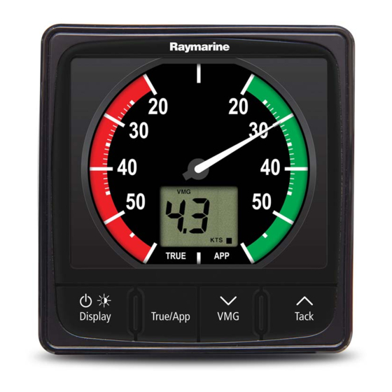
360º wind direction scale and can be used as a stand alone unit or as part of a SeaTalk or SeaTalk network. 2. i60 Close Hauled (CH) Wind — The i60 Close Instrument display hauled wind instrument is a repeater display which provides an expanded indication from Front bezel (eS style) 20º... -
Page 15: Chapter 3 Planning The Installation
Chapter 3: Planning the installation Chapter contents • 3.1 Installation checklist on page 16 • 3.2 Compatible transducers on page 16 • 3.3 System protocols on page 17 • 3.4 Tools required on page 17 • 3.5 Selecting a display location on page 18 •... -
Page 16: Installation Checklist
Installation Task The wind vane transducers listed below are Plan your system. compatible with the following instrument displays: Obtain all required equipment and tools. • i60 Wind Site all equipment. • i70 / i70s via iTC-5 converter Route all cables. Part... -
Page 17: System Protocols
3.3 System protocols 3.4 Tools required Tools required for installation Your product can be connected to various products and systems to share information and so improve the functionality of the overall system. These connections may be made using a number of different protocols. -
Page 18: Selecting A Display Location
Viewing angle considerations As display contrast, color and night mode performance are all affected by the viewing angle, Raymarine recommends you temporarily power up the display when planning the installation, to enable you to best judge which location gives the optimum... -
Page 19: Product Dimensions
3.6 Product dimensions 3.7 Wind vane transducer / rotavecta location requirements When selecting a location for your wind transducer it is important to consider a number of factors. The transducer's location must: • Allow reasonable access for installation and servicing. •... -
Page 21: Chapter 4 Cables And Connections
Chapter 4: Cables and connections Chapter contents • 4.1 General cabling guidance on page 22 • 4.2 Connections overview on page 22 • 4.3 Direct Power Connection on page 23 • 4.4 SeaTalkng® power supply on page 23 • 4.5 Transducer connections on page 26 •... -
Page 22: General Cabling Guidance
• Unless otherwise stated use only standard cables backbone spur cables of the correct type, supplied by Raymarine. NMEA 2000 SeaTalkng® • Ensure that any non-Raymarine cables are of the backbone to DeviceNet correct quality and gauge. For example, longer adaptor SeaTalk... -
Page 23: Direct Power Connection
4.3 Direct Power Connection 4.4 SeaTalkng® power supply Power is supplied to the product over the SeaTalkng® backbone. A SeaTalkng® backbone requires one 12 V dc power supply, connected to the SeaTalkng® backbone. This can be provided by: • a battery , via the distribution panel, •... -
Page 24: In-Line Fuse And Thermal Breaker Ratings
Where this is not please consult an authorized Raymarine dealer or possible and more than 1 item of equipment a suitably qualified professional marine electrician. -
Page 25: Sharing A Breaker
More information Raymarine recommends that best practice is observed in all vessel electrical installations, as detailed in the following standards: • BMEA Code of Practice for Electrical and Electronic Installations in Boats •... -
Page 26: Transducer Connections
Close hauled wind does not network using Raymarine's Instrument transducer include transducer connections as it is a repeater converter (iTC-5) and an i70 instrument, the data display. can then be repeated on an i50 / i60 unit. i60 transducer connections Blue Rotor + (Rotavecta) Rotor –... -
Page 27: Seatalk Ng Connection
4.7 SeaTalk connection Example: SeaTalk SPX system with transducer pods Note: In the example below, if an ACU-100 was used, the SeaTalk network would require a dedicated 12 V dc power supply because the ACU-100 does not supply power to the SeaTalk network. -
Page 28: Seatalk Connection
The power supply must be protected by a 5 A fuse or a circuit breaker providing equivalent protection. Raymarine recommends that the power is connected to a SeaTalk system in such a way that the current drawn on each side of the power connection point... -
Page 29: Chapter 5 Mounting
Chapter 5: Mounting Chapter contents • 5.1 Mounting on page 30 • 5.2 Front bezel on page 31 Mounting... -
Page 30: Mounting
5.1 Mounting Note: The supplied gasket provides a seal between the unit and a suitably flat and stiff mounting surface or binnacle. The gasket should Pre-mounting check be used in all installations. It may also be The product is designed to be surface mounted. necessary to use a marine-grade sealant if the Before mounting the unit, ensure you have: mounting surface or binnacle is not entirely flat and... -
Page 31: Front Bezel
5.2 Front bezel Removing the front bezel Note: Use care when removing the bezel. Do not use any tools to lever the bezel, doing so may cause damage. 1. Using your fingers pull the bezel away from the unit at the top and side, as shown in 2. The bezel will start to come away from the unit at the top and side. -
Page 33: Chapter 6 Getting Started
Chapter 6: Getting started Chapter contents • 6.1 Controls on page 34 • 6.2 Power on page 34 • 6.3 Data master on page 35 Getting started... -
Page 34: Controls
6.1 Controls 6.2 Power Powering on the unit The unit will automatically turn on with the system, unless it has previously been powered off using the Power button. With the unit powered off: 1. Press and hold the Power button until the screen turns on (approximately 2 seconds). -
Page 35: Data Master
You can check the instrument display’s software version and status by following the steps below. Note: The i60 CH Wind instrument is a repeater display. You cannot check or change the instrument status of an i60 CH Wind display... -
Page 37: Chapter 7 Calibration
Chapter 7: Calibration Chapter contents • 7.1 Calibration on page 38 • 7.2 User calibration on page 38 • 7.3 Intermediate calibration on page 39 • 7.4 Dealer calibration on page 40 Calibration... -
Page 38: Calibration
7.1 Calibration 7.2 User calibration Before first use the unit must be calibrated to ensure The i60 CH instrument display is a repeater display optimum performance. and as such does not require calibration, the steps below apply to the calibration of the i60 Wind The calibration settings are grouped into 3 instrument only. -
Page 39: Selecting The Unit Of Measure For Wind Speed Readings
Display and True / App Note: The i60 CH Wind instrument is a repeater buttons at the same time for approximately 2 display. You cannot check or change the seconds. -
Page 40: Dealer Calibration
15 with level 1 being the slowest update rate and level 15 the quickest. Note: Not available on the i60 CH wind instrument. Note: To exit the Dealer Calibration pages at any time, press and hold the Display and True/App... -
Page 41: Setting The Response Delay For Vmg Readings
Response page is displayed (3 presses from User Calibration Menu Access page). Enabling and disabling Boat Show Mode - i60 During normal operation: 1. Press and hold the Display and True / App buttons at the same time for approximately 14 4. -
Page 42: Resetting The Display To Factory Defaults - I60
Resetting the display to factory defaults - i60 During normal operation: 1. Press and hold the Display and True / App buttons at the same time for approximately 14 seconds, until the Dealer Calibration page is displayed. 2. Press the VMG and Tack buttons at the same time to display the User Calibration Menu Access page. -
Page 43: Chapter 8 Using Your Display
Chapter 8: Using your display Chapter contents • 8.1 Pages on page 44 • 8.2 i60 Wind operation on page 44 • 8.3 Illumination on page 46 Using your display... -
Page 44: Pages
*Low apparent wind angle Note: Alarms are only available on the i60 alarm Wind instrument, when set as a master unit. No alarms are available on the i60 Close hauled wind instrument. Tack Note: *These pages are temporary pages and will... -
Page 45: Using Tack And Vmg Buttons
During normal operation: any way.Apparent Wind Direction (AWD) — The compass direction that wind would appear to 1. Use the Display button to cycle through the be blowing across the vessel when it is making available pages. way. 2. Press and hold the Tack button for 3 seconds to reset the maximum wind speed to the current 2. -
Page 46: Illumination
GrP is displayed on-screen Note: The Group Illumination page is a temporary Adjusting the contrast — i60 page and will time-out to the previous page after The contrast level can be accessed using the Speed 8 seconds. -
Page 47: Chapter 9 Alarms
Chapter 9: Alarms Chapter contents • 9.1 Alarms on page 48 Alarms... -
Page 48: Alarms
1. Press any button to silence an active alarm. Instrument alarms Enabling / Disabling alarms Alarms available on the i60 Wind are listed below. Alarms can be enabled or disabled at any time. • High true wind speed With the relevant alarm page displayed: •... -
Page 49: Chapter 10 Maintaining Your Display
Chapter 10: Maintaining your display Chapter contents • 10.1 Service and maintenance on page 50 • 10.2 Condensation on page 50 • 10.3 Routine equipment checks on page 51 • 10.4 Product cleaning on page 51 • 10.5 Cleaning the display case on page 52 •... -
Page 50: Service And Maintenance
Certain atmospheric conditions may cause a small components. Please refer all maintenance amount of condensation to form on the unit's window. and repair to authorized Raymarine dealers. This will not damage the unit and will clear after the Unauthorized repair may affect your warranty. -
Page 51: Routine Equipment Checks
10.3 Routine equipment checks 10.4 Product cleaning Raymarine strongly recommends that you complete Best cleaning practices. a number of routine checks to ensure the correct and When cleaning products: reliable operation of your equipment. • If your product includes a display screen, do NOT... -
Page 52: Cleaning The Display Case
10.5 Cleaning the display case 10.6 Cleaning the display screen The display unit is a sealed unit and does not require A coating is applied to the display screen. This regular cleaning. If it is necessary to clean the unit, makes it water repellent, and prevents glare. -
Page 53: Chapter 11 Troubleshooting
Chapter 11: Troubleshooting Chapter contents • 11.1 Troubleshooting on page 54 • 11.2 Instrument troubleshooting on page 55 • 11.3 Power up troubleshooting on page 56 • 11.4 Miscellaneous troubleshooting on page 57 Troubleshooting... -
Page 54: Troubleshooting
All Raymarine products are, prior to packing and shipping, subjected to comprehensive test and quality assurance programs. However, if you experience problems with the operation of your... -
Page 55: Instrument Troubleshooting
11.2 Instrument troubleshooting Fault Cause Action Blank display. No power supply. • Check fuse / circuit breaker. • Check power supply. • Check SeaTalk / SeaTalk cabling and connector security. SeaTalk / SeaTalk information not being SeaTalk / SeaTalk cabling or connector •... -
Page 56: Power Up Troubleshooting
Software corruption In the unlikely event that the products software has become corrupted please try re-flashing the latest software from the Raymarine website. On display products, as a last resort, you can try to perform a ‘Power on Reset’, however this will delete all settings/presets and user data (such as waypoints... -
Page 57: Miscellaneous Troubleshooting
Check that the power source is of the correct voltage and erratic behavior. sufficient current. Software mismatch on system Go to www.raymarine.com and click on support for the (upgrade required). latest software downloads. Corrupt data / other unknown Perform a factory reset. -
Page 59: Chapter 12 Technical Support
Chapter 12: Technical support Chapter contents • 12.1 Raymarine product support and servicing on page 60 • 12.2 Checking the software version on page 61 Technical support... -
Page 60: Raymarine Product Support And Servicing
3614 905 Raymarine offers dedicated service departments for Sweden support.se@raymarine.com warranty, service, and repairs. (0)317 (Raymarine subsidiary) 633 670 Don’t forget to visit the Raymarine website to register your product for extended warranty benefits: Finland +358 support.fi@raymarine.com http://www.raymarine.co.uk/display/?id=788. (0)207 (Raymarine subsidiary) -
Page 61: Checking The Software Version
12.2 Checking the software version Follow the steps below to identify the software version of your unit. During normal operation: 1. Press and hold the Display (Power) and True / App buttons simultaneously for 4 seconds. The software version will be displayed on the screen. Technical support... -
Page 63: Chapter 13: Technical Specification
Chapter 13: Technical specification Chapter contents • 13.1 Technical specification on page 64 Technical specification... -
Page 64: Technical Specification
13.1 Technical specification Nominal supply voltage 12 V dc Operating voltage range 10 V dc to 16 V dc Power consumption • < 1 W Typical (Display only) • 2.4 W Maximum (Transducer connected) Current • 45 to 65 mA Typical (Display only) •... -
Page 65: Chapter 14 Spares And Accessories
Chapter 14: Spares and accessories Chapter contents • 14.1 Spares and Accessories on page 66 • 14.2 SeaTalk ng® cables and accessories on page 66 • 14.3 SeaTalk cable kits on page 68 Spares and accessories... -
Page 66: Spares And Accessories
Spares Description Part number SeaTalk cables and accessories for use with compatible products. R22168 i50 / i60 / i70 front bezel Description Part No Notes R22169 i50 / i60 / i70 Sun cover SeaTalk starter kit T70134 Includes:... - Page 67 Description Part No Notes SeaTalk to bare A06044 ends 3 m (9.8ft) spur SeaTalk Power A06049 cable SeaTalk A06031 Terminator A06028 Provides 1 x spur SeaTalk T-piece connection SeaTalk 5–way A06064 Provides 3 x spur connector connections SeaTalk A06030 backbone extender SeaTalk to E22158 Allows the connection...
-
Page 68: Seatalk Ng Cable Kits
14.3 SeaTalk cable kits SeaTalk starter kit (T70134) Quan- Parts included tity Connector A Cable Connector B Length Spur cable 3m (9.8ft) (A06040) Power cable 1m (3.3ft) (A06049) Backbone terminator (A06031) 5–way connector (A06064). Each connector block allows the connection of up to 3 compatible devices. - Page 69 Quan- Parts included tity Connector A Cable Connector B Length T-piece (A06028) Backbone terminator (A06031) SeaTalk Evolution cable kit (R70160) Quan- Parts included tity Connector A Cable Connector B Length Backbone cable 5m (16.4ft) ((A06036)) Power cable 1m (3.3ft) (A06049) Spur cable 1m (3.3ft) (A06040)
- Page 70 Quan- Parts included tity Connector A Cable Connector B Length T-piece (A06028) Backbone terminator (A06031) SeaTalk converter kit (E22158) Quan- Parts included tity Connector A Cable Connector B Length Power cable 1m (3.3ft) (A06049) Backbone terminator (A06031) Blanking plug(A06032) SeaTalk (3 pin) 0.4m (1.3ft) adapter cable (A06047)
-
Page 71: Appendix A Nmea 2000 Sentences
Appendix A NMEA 2000 sentences The i60 instrument range supports the following NMEA 2000 Parameter Group Number (PGN) sentences. PG name i60 Wind Transmit i60 Wind Receive ● ISO Acknowledgement 59392 ● ISO Request 59904 ● ● ISO Address claim 60928 ●... - Page 73 Index Servicing............7, 50 Strain relief, See Cable protection Backbone length..........23–24 Battery connection..........24 Technical support........... 60 Thermal breaker rating .......... 24 Troubleshooting............. 54 Cable bend radius ..........22 Cable connection, See Connecting cables Cable connector, See Connecting cables Warranty ..............
- Page 76 Raymarine UK Limited, Marine House, Cartwright Drive, Fareham, PO15 5RJ. United Kingdom. Tel: +44 (0)1329 246 700...