
Related Manuals for Bosch Rexroth CS351


Summary of Contents for Bosch Rexroth CS351
- Page 1 Betriebsanleitung Operating instructions CS351/ CC-CS351 I L RUN/STOP ERROR 3 609 929 B45, AF:12.2019, DE/EN...
- Page 2 Verwender nicht von eigenen Beurteilungen und Prüfungen. Es ist zu beachten, dass unsere Produkte einem natürlichen Verschleiß- und Alterungsprozess unterliegen. © Alle Rechte bei Bosch Rexroth AG, auch für den Fall von Schutzrechtsanmeldungen. Jede Verfügungsbefugnis, wie Kopier- und Weiter- gaberecht, bei uns.
-
Page 3: Table Of Contents
Bosch Rexroth AG 3/96 CS351/CC-CS351 | 3 609 929 B45/2019-12 Inhalt Zu dieser Anleitung...................4 Grundsätzliche Sicherheitshinweise..............5 Lieferumfang....................9 Produktbeschreibung..................10 Externe Schnittstellen..................15 Transport und Lagerung.................. 29 Montage......................30 Inbetriebnahme....................32 Betrieb......................34 Instandhaltung und Instandsetzung..............35 Instandsetzung....................35 Wartung......................40 Außerbetriebnahme..................41 Demontage und Austausch................41 Entsorgung..................... -
Page 4: Zu Dieser Anleitung
4/96 Bosch Rexroth AG CS351/CC-CS351 | 3 609 929 B45/2019-12 Zu dieser Anleitung Zu dieser Anleitung Gültigkeit der Dokumentation Diese Dokumentation gilt für Kompaktsysteme CS351 und CC-CS351. Mit Schraubsystemen Diese Anleitung enthält wichtige Informationen, bestehend aus Handschrauber ErgoSpin und um das Kompaktsystem CS351/CC-CS351 Kompaktsystem CS351E... -
Page 5: Grundsätzliche Sicherheitshinweise
Bosch Rexroth AG 5/96 CS351/CC-CS351 | 3 609 929 B45/2019-12 Grundsätzliche Sicherheitshinweise Grundsätzliche Halten Sie die in den technischen Daten genannten Betriebsbedingungen und Sicherheitshinweise Leistungsgrenzen ein. Die bestimmungsgemäße Verwendung schließt Das Kompaktsystem wurde gemäß den allgemein auch ein, dass Sie diese Anleitung und anerkannten Regeln der Technik hergestellt. - Page 6 6/96 Bosch Rexroth AG CS351/CC-CS351 | 3 609 929 B45/2019-12 Grundsätzliche Sicherheitshinweise Dieses Warnsymbol warnt Sie vor Qualifikation des Personals Gefahren für Ihre Gesundheit. Eine Fachkraft ist, wer aufgrund seiner fachlichen Befolgen Sie alle Ausbildung, seiner Kenntnisse und Erfahrungen Sicherheitshinweise, die diesem sowie seiner Kenntnisse der einschlägigen...
- Page 7 Bosch Rexroth AG 7/96 CS351/CC-CS351 | 3 609 929 B45/2019-12 Grundsätzliche Sicherheitshinweise Beachten Sie die örtlichen, anlagenspezifischen HINWEIS Bestimmungen und Erfordernisse und einen fachgerechten Einsatz von Werkzeugen, Hebe- HINWEIS weist auf eine Situation hin, die zu und Transporteinrichtungen, sowie die mittleren oder leichten Sachschäden führen...
- Page 8 Bosch Rexroth AG CS351/CC-CS351 | 3 609 929 B45/2019-12 8/96 Grundsätzliche Sicherheitshinweise Während des Betriebs Achten Sie auch auf einen Potentialausgleich Erlauben Sie den Zutritt zum unmittelbaren zwischen dem Werkstück und der Betriebsbereich der Anlage nur Personen, die Schraubspindel, sowie deren Aufnahmeplatte, vom Betreiber autorisiert sind.
-
Page 9: Lieferumfang
CS351/CC-CS351 | 3 609 929 B45/2019-12 Bosch Rexroth AG 9/96 Lieferumfang Lieferumfang Bei der Entsorgung Entsorgen Sie das Produkt nach den nationalen Im Lieferumfang sind enthalten: Bestimmungen Ihres Landes. Batterien dürfen nicht der normalen • 1 Kompaktsystem CS351 oder CC-CS351 Abfallsammlung zugeführt werden, sondern der... -
Page 10: Produktbeschreibung
CS351/CC-CS351 | 3 609 929 B45/2019-12 10/96 Bosch Rexroth AG Produktbeschreibung Produktbeschreibung Varianten des Kompaktsystems für Schraubspindeln sind: Leistungsbeschreibung • CS351S-D mit LC-Display. Im Kompaktsystem sind Leistungsteil, • CS351S-D IL mit LC-Display und integrierter Spannungsversorgung, Display, Steuerung, sowie Logik konform zu IEC 61131-3. - Page 11 CS351/CC-CS351 | 3 609 929 B45/2019-12 Bosch Rexroth AG 11/96 Produktbeschreibung Gerätebeschreibung Warnhinweis Er warnt vor den hohen elektrischen Spannungen im Kompaktsystem während des Betriebs und gibt Hinweise für die Wartung (siehe „Demontage und Austausch“ auf Seite 41). Schnittstellenübersicht Steuerung und Leistungsteil des Kompaktsystems verfügen über folgende...
- Page 12 CS351/CC-CS351 | 3 609 929 B45/2019-12 12/96 Bosch Rexroth AG Produktbeschreibung Außerhalb der Fronthaube: • nur bei CS351E-D NK/ CS351S-D NK: • 1 USB-Device-Schnittstelle zur CS351- – Schnittstellen zum Anschluss an den Steuerung (X3U3), Spezifikation 2.0 Systembus 350 (XDAC1, XDAC2)
- Page 13 CS351/CC-CS351 | 3 609 929 B45/2019-12 Bosch Rexroth AG 13/96 Produktbeschreibung X3U3 XDAC1 XDAC2 Abb. 2: Mögliche Schnittstellen des Kompaktsystems (Schnittstellen-Bestückung abhängig von CS-Variante)
- Page 14 CS351/CC-CS351 | 3 609 929 B45/2019-12 14/96 Bosch Rexroth AG Produktbeschreibung Tabelle 2: Kombinationen der Schnittstellen CS351S- CS351S- CS351S- CS351S- CS351S- – D IL G IL D NK CS351E- CS351E- CS351E- CS351E- CS351E- CS351E- Schnitt- D IL G IL D NK...
-
Page 15: Externe Schnittstellen
Bosch Rexroth AG 15/96 CS351/CC-CS351 | 3 609 929 B45/2019-12 Produktbeschreibung Tabelle 3: Pinbelegung X1N Externe Schnittstellen Spannung/ Beschreibung/ Signal Netzanschlussschnittstelle X1N Funktion Strom Die Auslieferung des Kompaktsystems erfolgt mit Netzanschluss 230 V /5 A, EU-Netzanschlussleitung und Netzanschluss- 120V /10A stecker mit Schraubklemmen. - Page 16 CS351/CC-CS351 | 3 609 929 B45/2019-12 16/96 Bosch Rexroth AG Produktbeschreibung Schnittstelle für Handschrauber XDS1 Schnittstelle XDS2 für Schraubspindel Die Verbindung des Handschraubers ErgoSpin/ Die Verbindung der Schraubspindel mit dem CC-ErgoSpin mit dem Kompaktsystem erfolgt Kompaktsystem erfolgt über eine Spindel- über eine Spindelanschlussleitung, die an die...
- Page 17 CS351/CC-CS351 | 3 609 929 B45/2019-12 Bosch Rexroth AG 17/96 Produktbeschreibung Motor-Stopp-Schnittstelle XDN1 XDN1 VORSICHT 1 2 3 4 Gefahr von Sach- und Personen- schäden! Sorgen Sie für erreichbare und wirksame Abb. 7: XDN1 Not-Halt-Einrichtungen. Ein Entriegeln der Not-Halt-Einrichtung darf keinen...
- Page 18 CS351/CC-CS351 | 3 609 929 B45/2019-12 18/96 Bosch Rexroth AG Produktbeschreibung Das maximale Drehmoment an den VORSICHT Schraubverbindungen der Klemmen bei XDN1 darf höchstens 0,3 Nm Gefahr von Sach- und Personenschäden! betragen. Gefährliche Körperströme durch unzureichende Schutzleiterverbindungen! VORSICHT Schutzleiterverbindungen dürfen nicht ...
- Page 19 CS351/CC-CS351 | 3 609 929 B45/2019-12 Bosch Rexroth AG 19/96 Produktbeschreibung Motor-Stopp-Beschaltung 1. Abschaltung über die internen Motorschütze Durch die Abschaltung über den Motorschütz sind die Motorphasen elektromechanisch getrennt von der Energieversorgung. Einsatz Motor-Stopp-Schalter XDN1 1 2 3 4 VEE NH1 1 mm Abb.
- Page 20 CS351/CC-CS351 | 3 609 929 B45/2019-12 20/96 Bosch Rexroth AG Produktbeschreibung 2. Abschaltung über die Endstufe Zusätzlich kann über die Endstufe oder zusammen mit der Abschaltung über die Motorschütze (doppelte Absicherung) der Motor-Stopp geschaltet werden. Einsatz Motor-Stopp-Schalter XDN1 1 2 3 4...
- Page 21 CS351/CC-CS351 | 3 609 929 B45/2019-12 Bosch Rexroth AG 21/96 Produktbeschreibung Die MAC-Adresse finden Sie auf dem Typschild, Ethernet-Schnittstelle X7E1 das oben auf dem Kompaktsystem angebracht ist. Die Schnittstelle ist als 8-polige RJ45-Buchse (10/100 TBase T) ausgelegt. RS232-Schnittstelle X3C1 Diese Schnittstelle dient zum An-schluss eines Druckers oder Scanners.
- Page 22 CS351/CC-CS351 | 3 609 929 B45/2019-12 22/96 Bosch Rexroth AG Produktbeschreibung A-Slot-Schnittstelle (A) B-Slot-Schnittstellen (B1, B2) Diese Schnittstellen sind für den Einsatz von Die Schnittstelle ist für den Einsatz von Schnittstellenmodulen des Typs B von Rexroth Schnittstellenmodulen des Typs A von Rexroth vorgesehen.
- Page 23 CS351/CC-CS351 | 3 609 929 B45/2019-12 Bosch Rexroth AG 23/96 Produktbeschreibung Steckplatz für den Massenspeicher (X6C1) USB-Host-Schnittstellen (X3U1, X3U2) Die Schnittstelle ist für den Einsatz des Diese Schnittstellen sind als Buchsen in Bauform Massenspeichers CF350 vorgesehen. A ausgeführt. Sie erfüllen die Anforderungen nach USB-Spezifikation 2.0.
- Page 24 CS351/CC-CS351 | 3 609 929 B45/2019-12 24/96 Bosch Rexroth AG Produktbeschreibung Tabelle 11: Belegung X3U3 DVI-Schnittstelle (XDVI) Beschrei- Span- Tabelle 12: Belegung X3U4 Signal bung/ nung/ Funktion Strom Span- Beschreibung/ Signal nung/ USB_S_VBUS Versorgung 5V 5V= / 0,5A Funktion Strom...
- Page 25 CS351/CC-CS351 | 3 609 929 B45/2019-12 Bosch Rexroth AG 25/96 Produktbeschreibung Tabelle 13: Belegung DVI-Schnittstelle Signal Beschreibung/ Funktion Spannung/ Strom TMDS Data 2– Data 2– DVI differentiell TMDS Data 2+ Data 2+ DVI differentiell TMDS Data 2 Schirm Schirmung für Data 2 Potential PE n.c.
- Page 26 CS351/CC-CS351 | 3 609 929 B45/2019-12 26/96 Bosch Rexroth AG Produktbeschreibung Schnittstellen zum Anschluss an den Tabelle 14: Distanzbolzen für Netzwerkleitungen Systembus (XDAC1, XDAC2) Her- Schlüssel- Gewin- Der im Kompaktsystem CS351x-D NK integrierte Länge Best.nr. weite steller Netzwerkkoppler NK350 ermöglicht den...
- Page 27 CS351/CC-CS351 | 3 609 929 B45/2019-12 Bosch Rexroth AG 27/96 Produktbeschreibung Schnittstelle XDAC2 (male) Schnittstelle XDAC1 (female) Diese Schnittstelle dient zum Anschluss der Diese Schnittstelle dient zum Anschluss der Netzwerkleitung NKLx um weitere Teilnehmer zu Netzwerkleitung NKLx um weitere Teilnehmer zu integrieren.
- Page 28 CS351/CC-CS351 | 3 609 929 B45/2019-12 28/96 Bosch Rexroth AG Produktbeschreibung LED-Anzeige An den drei LEDs an der Frontplatte XDAc1 (siehe Abb. 20) werden die Zustände des Netzwerkes angezeigt: • LED1 beschreibt den Netzwerkzustand der an XDAC1 angeschlossenen Teilnehmer, LED 1 LED 2 •...
-
Page 29: Transport Und Lagerung
CS351/CC-CS351 | 3 609 929 B45/2019-12 Bosch Rexroth AG 29/96 Transport und Lagerung Transport und Hex-Codierschalter Bei vernetzten Systemen Lagerung (Baugruppenträgern, Systemboxen oder Kompaktsystemen) muss vor der ersten Halten Sie bei Lagerung und Transport in jedem Inbetriebnahme die gültige Adresse am Hex- Fall die Umgebungsbedingungen ein, die in den Codierschalter eingestellt werden. -
Page 30: Montage
CS351/CC-CS351 | 3 609 929 B45/2019-12 30/96 Bosch Rexroth AG Montage Montage Kompaktsystem montieren VORSICHT VORSICHT Zerstörung elektrischer Komponenten! Gefahr von Sach- und Personenschäden! Gesundheitsgefährdung Die Montage des Kompaktsystems erfordert Zerstören Sie keine eingebauten grundlegende mechanische und elektrische Komponenten. Entsorgen Sie zerstörte Kenntnisse. - Page 31 CS351/CC-CS351 | 3 609 929 B45/2019-12 Bosch Rexroth AG 31/96 Montage 252,5 Abb. 22: Wandhalterung (Maße in mm) 1 Wandhalterung 2 Aushebesicherung...
-
Page 32: Inbetriebnahme
CS351/CC-CS351 | 3 609 929 B45/2019-12 32/96 Bosch Rexroth AG Inbetriebnahme Inbetriebnahme Die zulässige Einbaulage des Kompaktsystems ist senkrecht. Das Kompaktsystem sollte bei der Montage VORSICHT aneinandergereiht mindestens 10 mm und übereinander mindestens 300 mm Abstand Gefahr von Sach- und Personenschäden! besitzen. - Page 33 CS351/CC-CS351 | 3 609 929 B45/2019-12 Bosch Rexroth AG 33/96 Inbetriebnahme 1. Fronthaube entriegeln und öffnen. Inbetriebnahme des Kompaktsystems Um das Kompaktsystem in Betrieb zu nehmen, gehen Sie wie folgt vor: Bauen Sie sämtliche benötigten Schnittstellenmodule ein – Entriegeln Sie die Fronthaube und nehmen Sie sie ab (siehe Seite 33).
-
Page 34: Betrieb
CS351/CC-CS351 | 3 609 929 B45/2019-12 34/96 Bosch Rexroth AG Betrieb Betrieb Das Kompaktsystem darf nur an geerdeten Netzen betrieben werden. Der Betrieb an nicht direkt geerdeten Netzen (IT-Netz) ist VORSICHT unzulässig, da Luft- und Kriechstrecken im System überlastet werden können und die... -
Page 35: Instandhaltung Und Instandsetzung
CS351/CC-CS351 | 3 609 929 B45/2019-12 Bosch Rexroth AG 35/96 Instandhaltung und Instandsetzung Instandhaltung und Tabelle 18: Zustände der LED Instandsetzung Anzei- Diagnose keine Netz- oder GEFAHR Niederspannungsver- sorgung vorhanden Elektrische Spannungen! Netzspannung und blau Tod durch Stromschlag Niederspannung vorhanden Führen Sie Wartungsarbeiten am... - Page 36 CS351/CC-CS351 | 3 609 929 B45/2019-12 36/96 Bosch Rexroth AG Instandhaltung und Instandsetzung Sicherungen tauschen GEFAHR Elektrische Spannungen! Tod durch Stromschlag Führen Sie Wartungsarbeiten am Schraubkanal nur bei ausgeschaltetem Kompaktsystem und gezogenem Netzstecker durch. Sichern Sie die Anlage gegen Wiedereinschalten.
- Page 37 CS351/CC-CS351 | 3 609 929 B45/2019-12 Bosch Rexroth AG 37/96 Instandhaltung und Instandsetzung Abb. 28: Sicherungen F1 Sicherung Leistungskreis Si 10 A, GEFAHR 250 V, 6,3x32 mm träge, (Hersteller: ESKA/ENDRICH, Elektrische Spannungen! Bestellnummer UL632.727 Tod durch Stromschlag F2 Sicherung Leistungskreis Si 10 A, Stellen Sie bei der Montage der ...
- Page 38 CS351/CC-CS351 | 3 609 929 B45/2019-12 38/96 Bosch Rexroth AG Instandhaltung und Instandsetzung Batterie des Kompaktsystems tauschen VORSICHT Die eingebaute Batterie hat im ausgeschaltenen Zustand eine Lebensdauer von ca. vier Jahren ab Gefahr von Sach- und Personen- Fertigung. Im Betriebzustand erhöht sich die schäden!
- Page 39 CS351/CC-CS351 | 3 609 929 B45/2019-12 Bosch Rexroth AG 39/96 Instandhaltung und Instandsetzung • Verbrauchte Batterie entfernen. Batterie Reinigung und Pflege keinesfalls mit einem elektrisch leitenden Werkzeug (z. B. Pinzette) entnehmen - VORSICHT Kurzschlussgefahr. Nehmen Sie die Batterie mit der Hand aus der Halterung.
-
Page 40: Wartung
CS351/CC-CS351 | 3 609 929 B45/2019-12 40/96 Bosch Rexroth AG Wartung Wartung Test der Fehlerstromschutzeinrichtung Die Fehlerstromschutz- einrichtung ist nur beim Kompaktsystem CS351E für Handschrauber ErgoSpin verfügbar. Prüfen Sie die Funktion der Fehlerstrom- Schutzeinrichtung (FI) mittels Betätigen der Testtaste. Falls keine anderen Vorschriften vorliegen empfehlen wir den Test einmal monatlich, mindestens aber einmal halbjährlich... -
Page 41: Außerbetriebnahme
CS351/CC-CS351 | 3 609 929 B45/2019-12 Bosch Rexroth AG 41/96 Außerbetriebnahme/ Demontage und Austausch Demontage und Außerbetriebnahme Austausch Das Kompaktsystem ist eine Komponente, die nicht außer Betrieb genommen werden muss. Das Kompaktsystem ist als eine Einheit zu Daher enthält das Kapitel in dieser Anleitung betrachten. -
Page 42: Entsorgung
CS351/CC-CS351 | 3 609 929 B45/2019-12 42/96 Bosch Rexroth AG Entsorgung Entsorgung Um das Kompaktsystem zu demontieren, gehen Sie wie folgt vor: Umweltschutz 1. Schalten Sie das Kompaktsystem Achtloses Entsorgen des Kompaktsystems kann spannungsfrei und halten Sie die Entladezeit zu Umweltverschmutzungen führen. -
Page 43: Erweiterung Und Umbau
CS351/CC-CS351 | 3 609 929 B45/2019-12 Bosch Rexroth AG 43/96 Erweiterung und Umbau Erweiterung und Umbau Fehlersuche und Fehlerbehebung Ein Umbau des Kompaktsystems ist nicht zulässig. Falls Sie den aufgetretenen Fehler nicht beheben konnten, wenden Sie sich bitte an eine der Kontaktadressen, die Sie unter www.boschrexroth.com oder im... -
Page 44: Technische Daten
CS351/CC-CS351 | 3 609 929 B45/2019-12 44/96 Bosch Rexroth AG Technische Daten Technische Daten Tabelle 21: Allgemeine Daten Bezeichnung CS351E-D CS351E-G CS351S-D CS351S-G CS351E-D CS351S-D Bezeichnung IL CS351E-D IL CS351E-G IL CS351S-D IL CS351S-G IL – – Bezeichnung – –... - Page 45 Bosch Rexroth AG 45/96 CS351/CC-CS351 | 3 609 929 B45/2019-12 Technische Daten Tabelle 21: (Fortsetzung) Allgemeine Daten Bezeichnung CS351E-D CS351E-G CS351S-D CS351S-G CS351E-D CS351S-D Bezeichnung IL CS351E-D IL CS351E-G IL CS351S-D IL CS351S-G IL – – Bezeichnung – – –...
- Page 46 CS351/CC-CS351 | 3 609 929 B45/2019-12 46/96 Bosch Rexroth AG Technische Daten Tabelle 21: (Fortsetzung) Allgemeine Daten Bezeichnung CS351E-D CS351E-G CS351S-D CS351S-G CS351E-D CS351S-D Bezeichnung IL CS351E-D IL CS351E-G IL CS351S-D IL CS351S-G IL – – Bezeichnung – – –...
-
Page 47: Service Und Vertrieb
CS351/CC-CS351 | 3 609 929 B45/2019-12 Bosch Rexroth AG 47/96 Service und Vertrieb Service und Vertrieb Service Deutschland Tel.: +49 9352 40 50 60 Unser globales Servicenetz steht Ihnen in über E-Mail: 40 Ländern jederzeit zur Verfügung. Detaillierte service.svc@boschrexroth.de Informationen über unsere Servicestandorte in... -
Page 48: Anhang
CS351/CC-CS351 | 3 609 929 B45/2019-12 48/96 Bosch Rexroth AG Anhang Anhang 17.1 EAC-Konformitätserklärung Siehe Seite 93. Änderungen im Inhalt der EAC-Konformitäts- erklärung sind vorbehalten. Die derzeit gültige Ausgabe finden Sie im Medienverzeichnis: http://www.boschrexroth.com/ medienverzeichnis... - Page 49 CS351/CC-CS351 | 3 609 929 B45/2019-12 Bosch Rexroth AG 49/96 Contents About This Document ..................50 General safety instructions ................51 Scope of delivery ....................55 Product description ....................55 External interfaces....................60 Transport and storage ..................73 Assembly ......................74 Commissioning ....................76 Operation ......................78 Maintenance and repair ..................
-
Page 50: About This Document
CS351/CC-CS351 | 3 609 929 B45/2019-12 50/96 Bosch Rexroth AG About This Document About This Dokument Scope of the documentation This documentation is applicable for the CS351 and CC-CS351 Compact Systems. Tightening This manual contains important information on operations requiring documentation according to... -
Page 51: General Safety Instructions
CS351/CC-CS351 | 3 609 929 B45/2019-12 Bosch Rexroth AG 51/96 General safety instructions General safety Observe the operating conditions and instructions performance limits specified in the technical data. Proper use includes having read and understood these instructions, particularly chapter 2 “General The Compact System has been manufactured safety instructions”. - Page 52 CS351/CC-CS351 | 3 609 929 B45/2019-12 52/96 Bosch Rexroth AG General safety instructions The signal words have the following meanings: Safety instructions in this document In this manual, all activities entailing a danger of personal injury or damage to the equipment are DANGER preceded by a warning.
- Page 53 CS351/CC-CS351 | 3 609 929 B45/2019-12 Bosch Rexroth AG 53/96 General safety instructions Adhere to the following instructions Before commissioning, make sure that all the connection gaskets and plugs are installed General instructions correctly to ensure that they are leakproof and...
- Page 54 CS351/CC-CS351 | 3 609 929 B45/2019-12 54/96 Bosch Rexroth AG General safety instructions Only operate the Compact System in grounded Disposal networks. Operation in nongrounded networks Dispose of the product in accordance with the (IT network) is not permitted, as clearance and...
-
Page 55: Scope Of Delivery
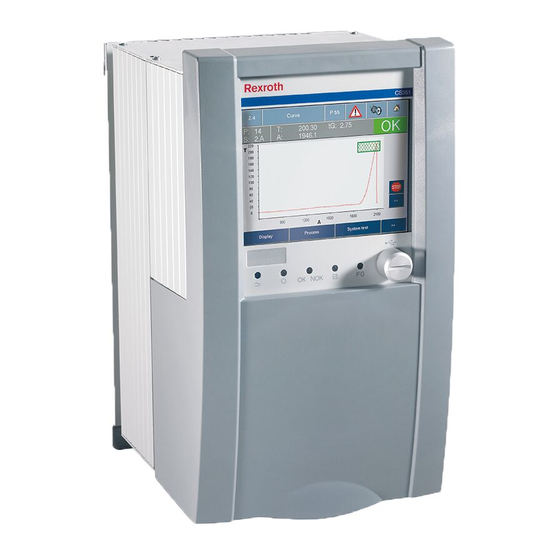
CS351/CC-CS351 | 3 609 929 B45/2019-12 Bosch Rexroth AG 55/96 Scope of delivery Scope of delivery Product description The delivery contents include: Performance description • 1 CS351 or CC-CS351 Compact System The Compact System combines a servo amplifier, power supply, display, controller, and •... - Page 56 CS351/CC-CS351 | 3 609 929 B45/2019-12 56/96 Bosch Rexroth AG Product description • CS351S-G IL with large color TFT display (VGA Legend relating to Fig. 1: 640x480) with integrated touchscreen and 1 Name plate integrated logic compliant with IEC 61131-3.
- Page 57 CS351/CC-CS351 | 3 609 929 B45/2019-12 Bosch Rexroth AG 57/96 Product description Outside the front cover: NOTE • 1 USB device interface for CS351 controller (X3U3), specification compatible with 2.0 Damage due to use of nonoriginal parts! (with screwedon cover) Damage to the Compact System •...
- Page 58 CS351/CC-CS351 | 3 609 929 B45/2019-12 58/96 Bosch Rexroth AG Product description X3U3 XDAC1 XDAC2 Fig. 2: Available interfaces of the Compact System (interface components depending on CS variant...
- Page 59 CS351/CC-CS351 | 3 609 929 B45/2019-12 Bosch Rexroth AG 59/96 Product description Tab.2: Interface combinations CS351S- CS351S- CS351S- CS351S- CS351S- – D IL G IL D NK CS351E- CS351E- CS351E- CS351E- CS351E- CS351E- Inter- D IL G IL D NK...
-
Page 60: External Interfaces
CS351/CC-CS351 | 3 609 929 B45/2019-12 60/96 Bosch Rexroth AG Product description External interfaces XDS1 interface for hand-held nutrunner The ErgoSpin/CC-ErgoSpin hand-held X1N power supply connection interface nutrunner is connected to the Compact System via a spindle connection cable that is The compact system is delivered with an EU connected to the 11-pin connection socket. - Page 61 CS351/CC-CS351 | 3 609 929 B45/2019-12 Bosch Rexroth AG 61/96 Product description XDS2 interface for tightening spindle 1 motor OFF interface XDN1 The tightening spindle is connected to the Compact System via a spindle connecting cable CAUTION that is connected to the 14-pin socket.
- Page 62 CS351/CC-CS351 | 3 609 929 B45-12 62/96 Bosch Rexroth AG Product description X D N 1 CAUTION 1 2 3 4 Risk of damage to persons and property! The user is obliged to maintain the systemspecific requirements for an emergency OFF system.
- Page 63 CS351/CC-CS351 | 3 609 929 B45/2019-12 Bosch Rexroth AG 63/96 Product description Motor OFF protective circuit 1. Cut-out via the internal motor contactors After a cut-out via the motor contactor, the motor phases are electromechanically isolated from the power supply.
- Page 64 CS351/CC-CS351 | 3 609 929 B45/2019-12 64/96 Bosch Rexroth AG Product description 2. Cut-out via the end step In addition, the motor OFF can be switched via the end step or along with the cut-out via the motor contactors (double protection).
- Page 65 CS351/CC-CS351 | 3 609 929 B45/2019-12 Bosch Rexroth AG 65/96 Product description Ethernet interface X7E1 The MAC address can be found on the name The interface has an 8-pin RJ45 socket plate on the top of the Compact System. (10/ 100 Base T) design.
- Page 66 CS351/CC-CS351 | 3 609 929 B45/2019-12 66/96 Bosch Rexroth AG Product description A slot interface (A) B slot interfaces (B1, B2) This interface is intended for use of type A These interfaces are intended for use of type B interface modules from Rexroth.
- Page 67 CS351/CC-CS351 | 3 609 929 B45/2019-12 Bosch Rexroth AG 67/96 Product description Slot for the mass storage (X6C1) Tab.10: X3U1, X3U2 assignment This interface is intended for the use of the Description/ Voltage/ Signal CF350 mass storage. function current 5 V supply 5 V= / 0.5...
- Page 68 CS351/CC-CS351 | 3 609 929 B45/2019-12 68/96 Bosch Rexroth AG Product description USB host interfaces (X3U4) • You can connect a DVI monitor with the following resolutions: These interfaces are designed as a type A socket. They meet the requirements according –...
- Page 69 CS351/CC-CS351 | 3 609 929 B45/2019-12 Bosch Rexroth AG 69/96 Product description Tab.13: DVI interface (XDVI) assignment Signal Description/ function Voltage/ current TMDS data 2– Data 2– DVI differential TMDS data 2+ Data 2+ DVI differential TMDS data 2 shield...
- Page 70 CS351/CC-CS351 | 3 609 929 B45/2019-12 70/96 Bosch Rexroth AG Product description Interfaces for connection to the system bus Tab.14: Spacer bolts for network lines (XDAC1, XDAC2) Manu- Wrench The NK350 network coupler integrated in the factu- Thread Length Order no.
- Page 71 CS351/CC-CS351 | 3 609 929 B45/2019-12 Bosch Rexroth AG 71/96 Product description Interface XDAC1 (female) Interface XDAC2 (male) This interface is intended for connecting an NKLx This interface is intended for connecting an NKLx network cable in order to integrate further users.
- Page 72 CS351/CC-CS351 | 3 609 929 B45/2019-12 72/96 Bosch Rexroth AG Product description LED display XDAc1 The network status is indicated by the three LEDs on the front panel (see Fig. 20): • LED 1 describes the network status of the...
-
Page 73: Transport And Storage
CS351/CC-CS351 | 3 609 929 B45/2019-12 Bosch Rexroth AG 73/96 Transport and storage Transport and storage Hex coding switch On networked systems (sibracks, system boxes or compact systems), the valid address must be For storing and transporting the product always... -
Page 74: Assembly
CS351/CC-CS351 | 3 609 929 B45/2019-12 74/96 Bosch Rexroth AG Assembly Assembly Assembling the Compact System CAUTION CAUTION Electrostatic discharge! Damage to the Compact System Risk of damage to persons and property! Comply with all the precautions for ESD ... - Page 75 CS351/CC-CS351 | 3 609 929 B45/2019-12 Bosch Rexroth AG 75/96 Assembly 252,5 Fig. 22: Wall bracket (dimensions in mm) 1 Wall bracket 2 Lift-out protection...
-
Page 76: Commissioning
CS351/CC-CS351 | 3 609 929 B45/2019-12 76/96 Bosch Rexroth AG Commissioning Commissioning The permissible installation position for the Compact System is vertical. During assembly, the Compact System should CAUTION have at least 10 mm space when lined up and at least 300 mm space above it. - Page 77 CS351/CC-CS351 | 3 609 929 B45/2019-12 Bosch Rexroth AG 77/96 Commissioning Removing the front cover Assembly: You can remove the front cover to improve 1. Push the axle pins in and insert the front cover. access to the interfaces. 2. Release the axle pins – both axle pins must 1.
-
Page 78: Operation
CS351/CC-CS351 | 3 609 929 B45/2019-12 78/96 Bosch Rexroth AG Operation Operation 7. 7. Assemble the front cover. 8. 8. Close and lock the front cover. 9. 9. Connect the hand-held nutrunner/tightening CAUTION spindle: 10. Connect the power supply connection cable. - Page 79 CS351/CC-CS351 | 3 609 929 B45/2019-12 Bosch Rexroth AG 79/96 Operation Tab.18: LED modes The Compact System may only be operated in grounded networks. Operation in Color Diagnosis networks that are not directly grounded (IT network) is not permitted, as clearance and...
-
Page 80: Maintenance And Repair
CS351/CC-CS351 | 3 609 929 B45/2019-12 80/96 Bosch Rexroth AG Maintenance and repair Maintenance and repair Exchanging fuses DANGER DANGER Electrical voltages! Electrical voltages! Electrocution Electrocution Do not carry out maintenance work on the Do not carry out maintenance work on the ... - Page 81 CS351/CC-CS351 | 3 609 929 B45/2019-12 Bosch Rexroth AG 81/96 Maintenance and repair Fig. 28: Fuses F1 Main circuit fuse Si 10 A, 250 V, DANGER 6.3x32 mm slow-blow, Manufacturer: ESKA/ENDRICH, order number Electrical voltages! UL632.727 Electrocution F2 Main circuit fuse Si 10 A, 250 V, Make sure when assembling the front ...
- Page 82 CS351/CC-CS351 | 3 609 929 B45/2019-12 82/96 Bosch Rexroth AG Maintenance and repair Changing the battery of the Compact System CAUTION When switched off, the installed battery has a service life of approximately four years from the Risk of damage to persons and property! date of production.The service life increases...
- Page 83 CS351/CC-CS351 | 3 609 929 B45/2019-12 Bosch Rexroth AG 83/96 Maintenance and repair Cleaning and care • Remove the dead battery. Under no circumstances should conductive tools (e.g.tweezers) be used to remove batteries CAUTION g.danger of short circuit. Remove the battery from the holder by hand.
-
Page 84: Maintenance
CS351/CC-CS351 | 3 609 929 B45/2019-12 84/96 Bosch Rexroth AG Maintenance and repair Maintenance Testing the residual-current-operated protective device The residual-current-operated protective device is only available with the CS351E Compact System for ErgoSpin hand-held nutrunners. Check the function of the residual-current- operated protective device (RCD) by actuating the test button. -
Page 85: Decommissioning
CS351/CC-CS351 | 3 609 929 B45/2019-12 Bosch Rexroth AG 85/96 Decommissioning/ Disassembly and replacement Decommissioning Disassembly and replacement The Compact System is a component that does not require decommissioning. As a result, this chapter of the manual does not contain any The Compact System must be considered a unit. -
Page 86: Disposal
CS351/CC-CS351 | 3 609 929 B45/2019-12 86/96 Bosch Rexroth AG Disposal Disposal Proceed as follows to disassemble the Compact System: Environmental protection 1. Switch off the power supply to the Compact Careless disposal of the Compact System could System and allow for a discharging time of at lead to pollution of the environment. -
Page 87: Extension And Conversion
CS351/CC-CS351 | 3 609 929 B45/2019-12 Bosch Rexroth AG 87/96 Extension and conversion/ Troubleshooting Extension and Troubleshooting conversion If you are not able to remedy an occurring defect, please contact one of the addresses Do not convert the Compact System. -
Page 88: Technical Data
CS351/CC-CS351 | 3 609 929 B45/2019-12 88/96 Bosch Rexroth AG Technical data Technical data Tab.21: General data Designation CS351E-D CS351E-G CS351S-D CS351S-G CS351E-D CS351S-D IL designation CS351E-D IL CS351E-G IL CS351S-D IL CS351S-G IL – – CC designation – –... - Page 89 CS351/CC-CS351 | 3 609 929 B45/2019-12 Bosch Rexroth AG 89/96 Technical data Tab.21: (continuation) General data Designation CS351E-D CS351E-G CS351S-D CS351S-G CS351E-D CS351S-D IL designation CS351E-D IL CS351E-G IL CS351S-D IL CS351S-G IL – – CC designation – – –...
- Page 90 CS351/CC-CS351 | 3 609 929 B45/2019-12 90/96 Bosch Rexroth AG Technical data Tab.21: (continuation) General data Designation CS351E-D CS351E-G CS351S-D CS351S-G CS351E-D CS351S-D IL designation CS351E-D IL CS351E-G IL CS351S-D IL CS351S-G IL – – CC designation – – –...
-
Page 91: Service And Sales
CS351/CC-CS351 | 3 609 929 B45/2019-12 Bosch Rexroth AG 91/96 Service and sales Service and sales Our global service network can be reached at Service Germany any time in over 40 countries. You can find Phone: +49 9352 40 50 60... -
Page 92: Appendix
CS351/CC-CS351 | 3 609 929 B45/2019-12 92/96 Bosch Rexroth AG Appendix Appendix 17.1 EAC-Declaration of Conformity See page 93. Changes in the content of the EAC declaration of conformity are reserved. The currently valid version is available in the media directory:... - Page 93 Bosch Rexroth AG 93/96 Приложение к инструкции по эксплуатации Приложение к инструкции по эксплуатации Вся продукция, произведенная под контролем концерна Bosch Rexroth AG, регулярно проходит обязательную процедуру подтверждения соответствия согласно действующему национальному законодательству и требованиям Технических регламентов Евразийского экономического союза (Таможенного союза).
- Page 94 CS351/CC-CS351 | 3 609 929 B45/2019-12 94/96 Bosch Rexroth AG Приложение к инструкции по эксплуатации Приложение к инструкции по эксплуатации изделия (действует только на территории стран Таможенного союза в рамках Евразийского экономического сообщества) ► Внимательно ознакомьтесь с указаниями по технике...
- Page 95 CS351/CC-CS351 | 3 609 929 B45/2019-12 Bosch Rexroth AG 95/96 Приложение к инструкции по эксплуатации Хранение необходимо хранить в сухом месте необходимо хранить вдали от источников повышенных температур и воздействия солнечных лучей при хранении необходимо избегать резкого перепада температур хранение без упаковки не допускается...
- Page 96 Bosch Rexroth AG Fornsbacher Str. 92 71540 Murrhardt Germany rfq.jt@boschrexroth.de www.boschrexroth.com/tightening Änderungen vorbehalten! / Subject to change! Printed in Germany 3 609 929 B45, AF:12.2019...
Need help?
Do you have a question about the Rexroth CS351 and is the answer not in the manual?
Questions and answers