Chapters
Table of Contents
Troubleshooting

Related Manuals for probst JUMBO-BV-VARIO


Summary of Contents for probst JUMBO-BV-VARIO
- Page 1 JUMBO-BV-VARIO Vacuum Kerb Stone Installation Machine JUMBO-BV-VARIO-B S-5220.0001 Machine JUMBO-BV-VARIO Vacuum Kerb Stone Installation JUMBO-BV-VARIO-B Order-No.: Serial-No.: 5220.0011 Translation of original operating instructions...
- Page 2 Bitte beachten Sie, dass das Produkt ohne vorliegende Betriebsanleitung in Landessprache nicht eingesetzt / in Betrieb gesetzt werden darf. Sollten Sie mit der Lieferung des Produkts keine Betriebsanleitung in Ihrer Landessprache erhalten haben, kontaktieren Sie uns bitte. In Länder der EU / EFTA senden wir Ihnen diese kostenlos nach.
-
Page 3: Table Of Contents
26/07/16 Contents JUMBO-BV-VARIO-B 2 / 40 Contents Contents ......................2 EC-Declaration of Conformity ................4 General ......................8 Authorized use ....................8 Survey and construction ..................9 Technical Data ....................10 Safety ......................11 Safety symbols ....................11 Safety Marking ....................11 Instructions for Installation, Maintenance and Operating Personnel ....... - Page 4 Transport ....................... 35 Maintenance ....................36 General ......................36 Suction Plates and Sealing Lips................37 Troubleshooting ..................... 37 Repairs ......................38 Safety procedures ................... 39 Hints to the identification plate ................40 Hints to the renting/leasing of PROBST devices ........... 40...
-
Page 5: Ec-Declaration Of Conformity
JUMBO-BV-VARIO-B 4 / 40 EC-Declaration of Conformity EG-Konformitätserklärung; EC-Declaration of conformity ;CE- Déclaration de Conformité; Certificato di conformita´norme CE; CE-Declaración de conformidad DESCRIPTION: JUMBO-BV-VARIO Vacuum Kerb Stone Installation Machine JUMBO BV VARIO-B Hersteller: PROBST GREIFTECHNIK VERLEGESYSTEME Manufacturer: Gottlieb-Daimlerstraße 6 Fabricant:... - Page 6 26/07/16 EC-Declaration of Conformity JUMBO-BV-VARIO-B 5 / 40 EN ISO 12100-2 2003 Sicherheit von Maschinen, Grundbegriffe, allgemeine (ISO 12100-2) Gestaltungsleitsätze, Teil 2: Technische Leitsätze und Spezifikationen. Safety of machinery; basic concepts, general principles for design; Part 2: principles and specifications.
- Page 7 26/07/16 EC-Declaration of Conformity JUMBO-BV-VARIO-B 6 / 40 DIN 45635-13 02.77 Geräuschemessung an Maschinen (Verdränger-, Turbo- und Strahlverdichter). Measurement of airborne noise emitted by machines (displacement-, turbo- and jet-compressors). Mesure sonore sur les machines (compresseur volumétrique, centrifuge et faisceau). Misurazioni del livello di rumorosità emesso dalle macchine (dislocazione-,turbo-e jet compressori) Medición de ruidos en maquinaria...
- Page 8 Compatibilidad electromagnética-Requisitos a aparatos electrodomésticos, Herramientas eléctricas y aparatos eléctricos similares. Parte 2: Inmunidad en contra de interferencias. Authorized person for EC-dokumentation: Name: J. Holderied Address: Probst GreiftechnikVerlegesysteme GmbH; Gottlieb-Daimler-Str. 6; D-71729 Erdmannhausen Signature: Erdmannhausen, 26.07.2016................(M. Probst, Managing director)
-
Page 9: General
Authorized use The device (JUMBO-BV-VARIO-B) must only be used for lifting kerbstones and non-porous stone slabs with a maximum weight of 150 kg (330 lbs) and is suitable for attaching to any type of wheel loader with a fork-lift carrier. -
Page 10: Survey And Construction
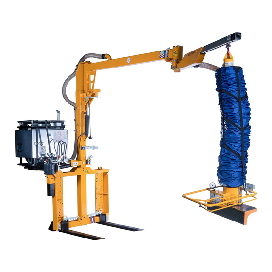
26/07/16 General JUMBO-BV-VARIO-B 9 / 40 Survey and construction Vacuum hose Vacuum hose Mast crane boom Petrol engine Lifting hose Wheel loader Pallet with Operating valve unit Kerbstones... -
Page 11: Technical Data
26/07/16 General JUMBO-BV-VARIO-B 10 / 40 Technical Data Type: JUMBO-BV-VARIO-B Vacuum kerbstone installation machine Order-Number: 5220.0011 Operating-range: 3.500 mm (~ 138 “) Carrying-capacity: 150 kg (330 lbs) Dead weight: ~520 kg (~ 1,150 lbs) Lifting speed: 0 – 40 m/min... -
Page 12: Safety
26/07/16 Safety JUMBO-BV-VARIO-B 11 / 40 Safety Safety symbols Danger to life! Identifies imminent hazard. If you do not avoid the hazard, death or severe injury will result. Danger Hazardous situation! Identifies a potentially hazardous situation. If you do not avoid the situation, injury or damage to property can result. - Page 13 26/07/16 Safety JUMBO-BV-VARIO-B 12 / 40 Use ear protection 2904.029 50 mm Swing range is only for the right area allowed (when working 2904.0474 86x142 direct on roadways – danger of accidents with motorcars). Swing range is only for the lift area allowed (when working direct 2904.0475...
-
Page 14: Instructions For Installation, Maintenance And Operating Personnel
26/07/16 Safety JUMBO-BV-VARIO-B 13 / 40 Instructions for Installation, Maintenance and Operating Personnel The device must be installed and maintained by qualified personnel, mechanics and electricians. Each person in your company involved in the installation, start-up, operation, maintenance, and repair of the device must have read and understood the operating instructions and especially the chapter "Safety"... -
Page 15: Special Hazards
26/07/16 Safety JUMBO-BV-VARIO-B 14 / 40 4.6 Special Hazards ● The operating range have to be covered for unauthorized persons, especially children. ● The workplace have to be sufficiently illuminated. Attention ● Take care handling wet, dirty and not solidified components. -
Page 16: Inspecting The Vacuum Hoses And Hose Clamps
26/07/16 Safety JUMBO-BV-VARIO-B 15 / 40 4.9.1 Inspecting the vacuum hoses and hose clamps ● Check that all vacuum hoses and hose clamps are securely seated. Tighten any loose connections. 4.9.2 Testing the vacuum reservoir ● See the sub-section "Leak test" in the section ”Maintenance”... -
Page 17: Function Control
26/07/16 Safety JUMBO-BV-VARIO-B 16 / 40 Correct any faults before using the device. If faults occur during operation, switch the device off and correct the faults before continuing work with the device. 4.13 Function Control ● Before using the device check the functions and the If there are any cracks, splits or damaged parts on working condition. -
Page 18: Damages Of Suction Plate
26/07/16 Safety JUMBO-BV-VARIO-B 17 / 40 4.16 Damages of suction plate Avoidance of damages: To avoid damages of the rubber seal on the suction plate (chinks, abrasion) take notice, that: during the operation (lifting, transporting and lowering) with the device, the suction plate does not brush or pump against other products or materials. -
Page 19: Safety Procedures Using Wheel Loader
26/07/16 Safety JUMBO-BV-VARIO-B 18 / 40 4.18 Safety procedures using wheel loader ● ● To prevent any injury and to reduce Avoid quick or jerky movements with noise always close the silencer hood. the device Jumbo BV vario-b. ● ●... -
Page 20: Installation
If the JUMBO-BV-VARIO is to be mounted using the hollow forks on to a machine (wheel loader) that the forks are not fixed rigid , suitable measures should be taken to make sure it is secure and that the forks cannot flip up or move on one side. -
Page 21: Connection To Wheel Loader
26/07/16 Installation JUMBO-BV-VARIO-B 20 / 40 Connection to wheel loader Fig. 1 Fig.2 Fig.3 ● ● ● Device must stand on plane Attach the correct size of paws Attach the lifting plate of the ground. (below – see arrows) wheel loader (on lower paws) Fig. -
Page 22: Mast/Crane Boom (Upwards/Downwards)
26/07/16 Installation JUMBO-BV-VARIO-B 21 / 40 Mast/crane boom (upwards/downwards) The mast/crane boom may only put up, when the device (JBV vario-b) is mounted onto the wheel loader and stands with the fork tines on even ground! Attention During the building up and dismantling of the mast/crane boom the stay of persons... - Page 23 26/07/16 Installation JUMBO-BV-VARIO-B 22 / 40 When the mast has reached the end position, f ix the mast with the ring screw in these position The adjustment of the mast in the driving direction takes place via the carriage plate of the carrier.
-
Page 24: Adjustment Of The Mast In The Driving Direction
26/07/16 Installation JUMBO-BV-VARIO-B 23 / 40 Adjustment of the mast in the driving direction Move the red lever in Position B Move lever (at the hand pump) in Operate the lever at hand pump to move Position I the mast to the right. -
Page 25: Fixing The Lifting Hose Unit
26/07/16 Installation JUMBO-BV-VARIO-B 24 / 40 ● The mast is adjusted in the optimal position, when the plumb bob is in plump. Fixing the lifting hose unit Fig. 24 Fig.25 Fig. 26 ● ● ● Insert lifting hose (8) at end of... -
Page 26: Fasten Lifting Hose Unit
26/07/16 Installation JUMBO-BV-VARIO-B 25 / 40 Fasten lifting hose unit Secure the vacuum hose lifter unit against swinging around before every driving with the wheel loader against swiveling by using the holder .Danger of injury! Danger Engage both spring bolts, that the vacuum hose lifter unit can not slide out from the holder. -
Page 27: Operating
26 / 40 Operating General It is not allowed to lift any load (kerbstone) with the vaccuum hose lifter unit, when the JUMBO-BV-VARIO is NOT attached on a wheel loader. Danger of tilting (see Picture B)!!! Picture A Picture B... -
Page 28: Adjusting The Hovering Position
26/07/16 Operating JUMBO-BV-VARIO-B 27 / 40 Adjusting the hovering position 6.3.1 Adjusting the hovering position without load Open and remove both snap hooks off the vacuum hose Vacuum hose is now released. corset in order to release the vacuum hose unit (for vacuum operation). -
Page 29: Adjusting The Hovering Position With Load
26/07/16 Operating JUMBO-BV-VARIO-B 28 / 40 ● Place the vacuum head directly above the load/kerb stone. ● Press the regulator lever (1) down. The lifting tube descends and the vacuum head lowers. ● Apply the vacuum head to the load. Distribute load evenly. - Page 30 26/07/16 Operating JUMBO-BV-VARIO-B 29 / 40 ● Slowly move the regulator lever (1) downward - "Lower". The lifting tube descends and the vacuum head lowers with the load. ● Do not operate the regulator lever control abruptly, while you firmly hold the handlebar (3), as this can cause the load to fall off, because the vacuum suddenly vanishes.
-
Page 31: Valve Tappet Adjustment
Operating 26/07/16 JUMBO-BV-VARIO-B 30 / 40 6.3.3 Valve tappet adjustment The distance of the tappet at the upper side of suction plate (mounting side operating valve unit) is adjusted to 63 mm (ex works) und secured with locknut. Never change these distance, otherwise the load (kerb stone) could fall down. - Page 32 Operating 26/07/16 JUMBO-BV-VARIO-B 31 / 40 When engine breakdown the load/kerb stones does not fall down (check valve). Residual vacuum lowers the operating valve unit/lifting hose unit with the sucked in load/kerb stone slowly. Do not use the device to jerk [sic!] seized loads/kerbstones! No work stoppage (pause) with sucked load/kerb stone, danger of the overheating of the vacuum blower!!! Adjust engine speed in such way that a minimum vacuum of -0.42 bar is present (see ...
- Page 33 26/07/16 Operating JUMBO-BV-VARIO-B 32 / 40 ● ● Remove the operating valve unit from the holder (). Pull at the cord () to release the locking lever at the gear ring (on the crane boom). ● ● Remove both socket pins at the crane boom () to Operating range of the crane boom around 360°.
- Page 34 26/07/16 Operating JUMBO-BV-VARIO-B 33 / 40 The using of the working range of the crane boom around 360° is strictly forbidden, when working direct on roadways – danger of accidents with motorcars, if vacuum lifting hose unit swings in to the roadway area! Prohibition The swing area of the vacuum lifting hose must be limited for the dangerous area (trailing roadway).
- Page 35 26/07/16 Operating JUMBO-BV-VARIO-B 34 / 40 ● Insert the corresponding 2 socket pins (left side in direction of travelling) at the crane boom () to delimit the working range of the crane boom to the left.
-
Page 36: Transport
Operating 26/07/16 JUMBO-BV-VARIO-B 35 / 40 6.4 Transport The device can be transported on a car trailer (considering the dimensions and allowable total weight). The transport of the device Jumbo BV vario-b (e.g. on a trailer) with an unsecured crane boom is strictly forbidden. -
Page 37: Maintenance
26/07/16 Maintenance JUMBO-BV-VARIO-B 36 / 40 Maintenance General To ensure the correct function, safety and service life of the device the following points must be executed in the maintenance interval. Used only original spare parts, otherwise the warranty expires. All operations may only be made in unpressurised, electro less and closed state of the device! ●... -
Page 38: Suction Plates And Sealing Lips
26/07/16 Maintenance JUMBO-BV-VARIO-B 37 / 40 Suction Plates and Sealing Lips Clean the sealing lips with compressed air and/or water jet once per week to remove any objects and dirt such as sand, stone particles, dust etc. Clean slot in the sealing lip with a cloth and / or blow out with compressed air. -
Page 39: Repairs
26/07/16 Maintenance JUMBO-BV-VARIO-B 38 / 40 Engine is defective Check the engine/call customer service Petrol engine goes out and Gasoline supply interrupted Check gasoline lines and fuel level in tank. immediate re-starting is not Ignition coil is defective Check ignition coil and if necessary possible exchange. -
Page 40: Safety Procedures
26/07/16 Maintenance JUMBO-BV-VARIO-B 39 / 40 Safety procedures It is the contructors responsibility to ensure that the We recommend, that after checking the device is checked by an expert in periods of max. 1 device the badge „Safety checked“ is year and all recognized errors are removed (... -
Page 41: Hints To The Identification Plate
Example: Hints to the renting/leasing of PROBST devices With every renting/leasing of PROBST devices the original operating instructions must be included unconditionally (in deviation of the users country's language, the respective translations of the original operating instructions must be delivered additionally)! - Page 42 VCG = vertical centre of gravity Tragfähigkeit / Working Load Limit WLL: kg / Eigengewicht / Dead Weight: kg / 1300 Product Name: Vacuum kerbstone installation machine JUMBO-BV-VARIO-B © all rights reserved conform to ISO 16016 Datum Name Benennung Jumbo BV Vario-b Vakuum-Bordstein Erst.
- Page 43 42200369 42200366 siehe separate Liste see separate list siehe separate Liste see separate list 42100132 42100539 © all rights reserved conform to ISO 16016 Datum Name Benennung Jumbo BV Vario-b Vakuum-Bordstein Erst. 10.8.2011 Perumal.Hurth -Verlegegerät, Benzinantrieb Gepr. 19.3.2019 R.Seidel Artikelnummer/Zeichnungsnummer Blatt E52200011 Zust.
- Page 44 21050017 23200002 42200101 42200276 21050017 siehe separate Liste see separate list 27000010 © all rights reserved conform to ISO 16016 Datum Name Benennung Vakuum-Gebläseeinheit kpl. Erst. 24.1.2014 Ralf.Northe mit Anbauteilen für Jumbo BV-b Gepr. 15.9.2016 I.Krasnikov mit E-Start, VGE-3RGb-E und Gehäuse Gebläse BV Artikelnummer/Zeichnungsnummer Blatt E42200369...
- Page 45 20100022 42200215 21000075 42200314 42200021 21990003 20040013 21050054 42300046 20000130 20000127 42200023 26190002 20400001 20100014 26920007 42200024 42200037 42200055 26900001 42200414 siehe separate Liste see separate list 20000009 42200217 21060002 24200008 20000130 42200174 20040004 20000127 21650001 20040003 24200003 21650001 20000004 20100014 20000004 ©...
- Page 46 42200311 26100022 20100015 42200029 20100005 20000021 42200028 21110003 21750002 21110002 21410002 21410001 20000014 22140206 22140492 21100008 27150002 22060036 27010025 20000014 22140493 20000026 25000008 complete with insert 42100085 Filter-Patrone Filter insert 20530015 42200310 22000582 20100015 20100017 21070090 20100022 42200441 20000012 20100015 42200027 42200032 21070001...
- Page 47 20000010 20400002 42200001 42200149 siehe separate Liste see separate list 20000010 42200333 siehe separate Liste 20400002 see separate list 20000010 20400002 42200356 siehe separate Liste see separate list 42100568 42200094 siehe separate Liste siehe separate Liste see separate list see separate list 42200354 siehe separate Liste see separate list...
- Page 48 siehe Hydraulikschaltplan see circuit diagramm 42920006 42200462 42200365 42200358 20440038 20000017 © all rights reserved conform to ISO 16016 Datum Name Benennung Baugruppe Handpumpe mit Befestigung Erst. 16.8.2011 Perumal.Hurth Gepr. 15.3.2016 J.Werner zu Jumbo BV Vario Benzin / Diesel 20100016 Artikelnummer/Zeichnungsnummer Blatt E42200367...
- Page 49 Stückliste nur zur Information, Pro Alpha Stückliste hat Priorität Oberflächen- Format Maßstab: Gewicht: behandlung © all rights reserved conform to ISO 16016 Benennung Datum Name HD-Schaltplan 12.4.2010 Perumal.Hurth Erst. JUMBO-BV-VARIO-B/D/H Gepr. 24.11.2014 R.Northe Werkstoff: Kunde: Artikelnummer/Zeichnungsnummer Zg. überarbeitet 24.11.2014 Blatt 42920006 Pos.27,36,38 geänd. 21.11.2014 mit Drossel 22060021 16.9.2016...
- Page 50 21050143 21050143 20100047 30340034 20540021 20100047 21050143 20100047 20530014 21050143 20530012 20100047 30340034 20540021 20530014 20100016 21600025 22200043 20100016 42200331 20530012 30300067 30300067 20530012 20000018 20000018 © all rights reserved conform to ISO 16016 Datum Name Benennung Mast kompl. für BV Vario Erst.
- Page 51 20100015 20400002 42200445 16100004 © all rights reserved conform to ISO 16016 Datum Name Benennung Ausgleichspendel kpl. Erst. 24.7.2012 M.Kaltenbach Gepr. 7.5.2019 R.Seidel Artikelnummer/Zeichnungsnummer Blatt E42200001 Zust. Urspr. V009-310 Ers. f. Ers. d.
- Page 52 30340034 42200042 siehe separate Liste 30340034 see separate list 20000036 42200446 siehe separate Liste 20440008 see separate list 21590068 20540021 20400101 21010051 21400026 20540021 21050017 21590068 21050088 42300012 21350026 42200034 21050017 21600025 21400026 21400027 © all rights reserved conform to ISO 16016 Datum Name Benennung...
- Page 53 20000036 20400030 20440008 33250116 21350026 21590068 42200335 42200334 siehe separate Liste see separate list 20400101 21400026 21590068 21350026 21400026 21400027 © all rights reserved conform to ISO 16016 Datum Name Benennung Knickausleger 150-3500 Zukaufteil Erst. 14.3.2017 J.Werner Gepr. 18.1.2018 R.Northe Artikelnummer/Zeichnungsnummer Blatt E42200446...
- Page 54 20100017 20100017 34010105 20100017 20350005 42200340 20000072 20000072 20000070 © all rights reserved conform to ISO 16016 Datum Name Benennung Vorderarm Knickausleger kompl. 150-3500 Erst. 24.9.2013 Ralf.Northe Gepr. 27.3.2018 R.Northe Artikelnummer/Zeichnungsnummer Blatt E42200335 Zust. Urspr. Ers. f. Ers. d.
- Page 55 33500026 20100015 21070062 21350006 20000007 20100014 21720001 20000012 20000126 21020013 © all rights reserved conform to ISO 16016 Datum Name Benennung Fahrwagen kompl. für Hubeinheit TM Erst. 25.7.2012 M.Kaltenbach Gepr. 15.9.2016 I.Krasnikov Artikelnummer/Zeichnungsnummer Blatt E42200042 Zust. Urspr. Ers. f. Ers. d.
- Page 56 33501437 20540033 42100567 20020006 © all rights reserved conform to ISO 16016 Datum Name Benennung Aufnahme für Bedieneinheit BE Erst. 13.10.2011 Perumal.Hurth Gepr. 15.9.2016 I.Krasnikov Artikelnummer/Zeichnungsnummer Blatt E42100568 Zust. Urspr. Ers. f. Ers. d.
- Page 57 20540001 20530013 20000035 20440008 20100018 20000020 20000169 20000020 20000092 20000092 20100018 42200004 20100016 20100019 20440008 20100016 20000092 42200004 © all rights reserved conform to ISO 16016 20000092 Datum Name Benennung Rahmen kompl. für BV Vario Erst. 25.7.2012 M.Kaltenbach Gepr. 7.5.2019 R.Seidel Artikelnummer/Zeichnungsnummer Blatt...
- Page 58 42200093 42200095 42200096 42200096 20450008 20000159 © all rights reserved conform to ISO 16016 Datum Name Benennung Set Pratzen-Uni mit Unterlagen 3 und 5 mm Erst. 7.5.2019 R.Seidel Gepr. 7.5.2019 R.Seidel Artikelnummer/Zeichnungsnummer Blatt E42200094 Zust. Urspr. Ers. f. Ers. d.
- Page 61 Filterübersicht / Filter overview JUMBO-BV-B/-VARIO-B JUMBOMOBIL-B/-VARIO-B 25000008 Luftfilter Euro-Piclon für JM und BV inkl. Filterpatrone Air filter complete for JM and BV, incl. filter cartridge 25050010 Filtermatte für BE 174x111 mm Filter mat for BE 174x111 mm 26900001 Kraftstofffilter für BV-Tank (8 Liter) M&H Nr.: WK 31/4 Fuel filter for BV-tank (8 litre) M&H No.: WK 31/4 26900021 Luftfiltermatte für GXV270 Typ:17218-ZE8-003 auch 17218...
- Page 62 A52200011 JUMBO-BV-VARIO-B A52200012 JUMBO-BV-VARIO-H A52200013 JUMBO-BV-VARIO-D 29040107 Auf beiden Seiten/ On both sides 29040730 29040383 29040056 29040107 29040204 29040666 29040207 Auf beiden Seiten/ on both sides P 04.10.2018_V0 1 / 6 Einige der Abbildungen sind möglicherweise optionales Zubehör des Gerätes/Some of pictures may be optional equipment of the device.
- Page 63 A52200011 JUMBO-BV-VARIO-B A52200012 JUMBO-BV-VARIO-H A52200013 JUMBO-BV-VARIO-D Linke Seite der Maschine / Rechte Seite der Maschine / left side of the machine right side of the machine 29040707 29040706 29040107 Auf beiden Seiten/ on both sides 29040704 29040705 P 04.10.2018_V0 2 / 6...
- Page 64 A52200011 JUMBO-BV-VARIO-B A52200012 JUMBO-BV-VARIO-H A52200013 JUMBO-BV-VARIO-D Gilt für/applies to: JUMBO-BV-VARIO-H | 52200012 29040339 29040266 29040526 29040525 29040265 29040451 29040298 29040687 P 04.10.2018_V0 3 / 6 Einige der Abbildungen sind möglicherweise optionales Zubehör des Gerätes/Some of pictures may be optional equipment of the device.
- Page 65 A52200011 JUMBO-BV-VARIO-B A52200012 JUMBO-BV-VARIO-H A52200013 JUMBO-BV-VARIO-D Gilt für/applies to: JUMBO-BV-VARIO-B | 52200011 29040298 29040339 29040624 29040340 29040451 29040329 (DE) 29040330 (GB) 29040476 29040331 (FR) 29040687 P 04.10.2018_V0 4 / 6 Einige der Abbildungen sind möglicherweise optionales Zubehör des Gerätes/Some of pictures may be optional equipment of the device.
- Page 66 A52200011 JUMBO-BV-VARIO-B A52200012 JUMBO-BV-VARIO-H A52200013 JUMBO-BV-VARIO-D Gilt für/applies to: JUMBO-BV-VARIO-D | 52200013 29040483 29040476 29040451 29040687 29040298 29040339 P 04.10.2018_V0 5 / 6 Einige der Abbildungen sind möglicherweise optionales Zubehör des Gerätes/Some of pictures may be optional equipment of the device.
- Page 67 A52200011 JUMBO-BV-VARIO-B A52200012 JUMBO-BV-VARIO-H A52200013 JUMBO-BV-VARIO-D 29040666 29040385 29040384 Typenschild Bedieneinheit Typenschild Hubeinheit P 04.10.2018_V0 6 / 6 Einige der Abbildungen sind möglicherweise optionales Zubehör des Gerätes/Some of pictures may be optional equipment of the device.
- Page 68 Vacuum Hose Lifter Components Lifting hose unit with Operating Valve Unit Keep these Operating Instructions for future use ! Status 08.2012 / Index 05 Page 1/15...
- Page 69 Vacuum Hose Lifter Components Lifting hose unit with Operating Valve Unit Table of Contents Safety Instructions for the Company Instructions for the Installation, Maintenance and Operating Personnel Hazard Alert Symbols in this Manual Installation Site Requirements Intended Use Emissions Special Hazards Workplace Instructions for the Operator 1.10 Equipment for Personal Protection...
- Page 70 Vacuum Hose Lifter Components Lifting hose unit with Operating Valve Unit Special Features The unit is equipped with the following special feature(s): (See the Appendix for special operating instructions and spare parts.) If the special features require a separate list of spare parts or parts subject of consumption, the corresponding list in section "Spare parts"...
-
Page 71: Safety
Vacuum Hose Lifter Components Lifting hose unit with Operating Valve Unit Safety 1.1 Instructions for the The Vacuum Hose Lifter has been manufactured according to current technological standards and is safe. Still, it will present hazards Company if the device is not operated by qualified or, at least trained staff, ... -
Page 72: Intended Use
Danger forbidden! Unauthorized alteration of the lifting device is forbidden for safety reasons! Only suction plates of the manufacturer PROBST shall be used!!! Some suction plates which can be mounted to the device will reduce its carrying capacity. The maximum load is indicated on each suction plate. -
Page 73: Equipment For Personal Protection
Vacuum Hose Lifter Components Lifting hose unit with Operating Valve Unit 1.10 Equipment for Wear safety shoes when operating the device. Personal Before transporting dangerous goods the appropriate safety clothes have to be put on. Protection 1.11 Behaviour in As an example sudden power failure is an emergency (the device switches off invariably!). -
Page 74: Description
Vacuum Hose Lifter Components Lifting hose unit with Operating Valve Unit Description 3.1 Components of The Vacuum Hose Lifter consists essentially out of: the J UMBO Pos. Description Remarks Coupling customer connection Rotary suction fitting customer connection Lifting tube customer connection Operating unit with regulator handle Securing net... -
Page 75: Accessories
Vacuum Hose Lifter Components Lifting hose unit with Operating Valve Unit 3.5 Accessories The installation of a dust filter is urgently recommended to protect the fan from all Dust Filter kinds of dirt (dust from surroundings, dirty loads etc.) Observe the enclosed installation instructions for dust filter. Note: If no dust filter is used, foreign objects must be excluded from the guarantee as a possible cause of failure. - Page 76 Vacuum Hose Lifter Components Lifting hose unit with Operating Valve Unit Mount the rotary suction fitting (7) to the transport trailer (5) of the crane. Fasten it safely! Insert the transport trailer into the crane jib (2). Mount the end stop (6) at the end of the crane jib. Never work without an end stop on the crane jib, otherwise the lifting device can fall off.
-
Page 77: Replacing The Lifting Tube
Vacuum Hose Lifter Components Lifting hose unit with Operating Valve Unit 4.3 Replacing the The lifting tube can be replaced on-site. lifting tube The lifting tube must always be installed with the reinforced section at the bottom! Caution Procedure: Clamp the rotary inlet in a vice, holding it by the screws of the tube holder (Fig. -
Page 78: Operating
Vacuum Hose Lifter Components Lifting hose unit with Operating Valve Unit Operating 5.1 Safety Local safety requirements are fully applicable. The following safety instructions are complimentary to the rules in force and do not supersede the latter: Instructions Wear safety shoes. ... - Page 79 Vacuum Hose Lifter Components Lifting hose unit with Operating Valve Unit Turn the adjusting screw (2) to adjust the hovering position with the load. Adjusting the hovering Caution: Do not confuse this adjustment with the hovering position without load. position with load ...
-
Page 80: Trouble Shooting
Vacuum Hose Lifter Components Lifting hose unit with Operating Valve Unit Trouble The device must be installed and maintained by qualified personnel, mechanics and electricians. Any work on the electrical equipment may be carried out only by a Shooting qualified electrician. After each repair or maintenance job check the guards as described in the Operating Manual ”Safety”. -
Page 81: Maintenance
Vacuum Hose Lifter Components Lifting hose unit with Operating Valve Unit Maintenance 7.1 General Notes The Vacuum Hose Lifter may be installed and maintained only by qualified personnel such as mechanics and electricians. After any repair or maintenance work, check the safety devices as described in the section "Safety". -
Page 82: Notes On The Name Plate
Vacuum Hose Lifter Components Lifting hose unit with Operating Valve Unit Notes on the On the nameplate the main data for the lifting device is indicated. The nameplate is firmly connected to the device. Name Plate The nameplate contains the following information: Type Device number Order number... - Page 83 Hubeinheit mit Bedieneinheit Ersatzteile/ /Spare Parts Hubeinheit / Lifting Hose Assy Dreheinheit / Rotation Unit...
- Page 84 Hubeinheit mit Bedieneinheit Ersatzteile/ /Spare Parts Hubeinheit / Lifting Hose Assy Menge / Abmessung / Pos. Bezeichnung Description Art. No. Legende Amount Dimension G 2“ - L 56 - D 66,3 G 2“ - L 56 - D 66,3 2700.0007 Flachsauggreifer_PFG Flat suction pad_PFG 4210.0610...
- Page 85 Hubeinheit mit Bedieneinheit Ersatzteile/ /Spare Parts Ventileinheit, Bedieneinheit / Valve Unit, Operating handle Ventileinheit / Valve Unit...
- Page 86 Hubeinheit mit Bedieneinheit Ersatzteile/ /Spare Parts Ventileinheit, Bedieneinheit / Valve Unit, Operating handle Menge / Abmessung / Pos. Bezeichnung Description Art. No. Legende Amount Dimension Ventilgehäuse kpl. Valve casing compl. 4210.0612 Federklappe Spring flap 4210.0608 Reibbelag Friction lining 4210.0613 Scheibe Disk 4210.0614 Schieber...
- Page 87 05/04/12 20:08:50 32Z5N600_001 INTRODUCTION Thank you for purchasing a Honda engine. We want to help you to get the best results from your new engine and to operate it safely. This manual contains information on how to do that; please read it OWNER’S MANUAL carefully before operating the engine.
-
Page 88: Spark Plug
05/04/12 20:09:12 32Z5N600_002 SAFETY INFORMATION COMPONENT & CONTROL LOCATION RECOIL STARTER Understand the operation of all controls and learn how to stop the engine quickly in case of emergency. Make sure the operator STARTER GRIP OIL FILLER CAP/ DIPSTICK receives adequate instruction before operating the equipment. Do not allow children to operate the engine. -
Page 89: Features
05/04/12 20:09:28 32Z5N600_003 FEATURES BEFORE OPERATION CHECKS OIL ALERT SYSTEM (applicable types) IS YOUR ENGINE READY TO GO? The Oil Alert system is designed to prevent engine damage caused by an insufficient amount of oil in the crankcase. Before For your safety, and to maximize the service life of your the oil level in the crankcase can fall below a safe limit, the Oil equipment, it is very important to take a few moments before you Alert system will sound a buzzer, warning you that oil needs to be... -
Page 90: Operation
05/04/12 20:09:46 32Z5N600_004 OPERATION STARTING THE ENGINE SAFE OPERATING PRECAUTIONS Move the fuel valve lever to the ON position. FUEL VALVE LEVER Before operating the engine for the first time, please review the SAFETY INFORMATION section on page and the BEFORE OPERATION CHECKS on page . -
Page 91: Electric Starter
05/04/12 20:10:02 32Z5N600_005 Operate the starter. STOPPING THE ENGINE RECOIL STARTER To stop the engine in an emergency, simply move the control lever to the OFF position. Under normal conditions, use the Pull the starter grip lightly until you feel resistance, then pull following procedure. -
Page 92: Setting Engine Speed
05/04/12 20:10:07 32Z5N600_006 SETTING ENGINE SPEED Position the control lever for the desired engine speed. The control lever shown here will be connected to a remote control on the equipment powered by this engine. Refer to the instructions provided with that equipment for remote control information and engine speed recommendations. -
Page 93: Servicing Your Engine
05/04/12 20:10:28 32Z5N600_007 SERVICING YOUR ENGINE MAINTENANCE SCHEDULE THE IMPORTANCE OF MAINTENANCE REGULAR SERVICE PERIOD (3) Each First Every 3 Every 6 Every Refer Good maintenance is essential for safe, economical and trouble- Perform at every Month Months Months Year free operation. -
Page 94: Recommended Oil
05/04/12 20:10:46 32Z5N600_008 REFUELING Refuel in a well-ventilated area before starting the engine. If the engine has been running, allow it to cool. Refuel carefully to avoid Recommended Fuel spilling fuel. Do not fill the fuel tank completely. Fill tank to the Unleaded gasoline upper limit level below the filler neck of the fuel tank to allow for U.S. - Page 95 05/04/12 20:11:02 32Z5N600_009 Oil Level Check Screw in the oil filler cap/dipstick securely. Check the engine oil level with the engine stopped and in a level OIL FILLER CAP/DIPSTICK position. Remove the oil filler cap/dipstick and wipe it clean. Insert and remove the oil filler cap/dipstick without screwing it into the oil filler neck.
- Page 96 05/04/12 20:11:27 32Z5N600_010 AIR CLEANER SPARK PLUG A dirty air cleaner will restrict air flow to the carburetor, reducing Recommended Spark Plugs: BPR5ES (NGK) engine performance. If you operate the engine in very dusty areas, W16EPR-U (DENSO) clean the air filter more often than specified in the MAINTENANCE SCHEDULE.
- Page 97 05/04/18 14:40:50 32Z5N600_011 HELPFUL TIPS & SUGGESTIONS SPARK ARRESTER (applicable types) The spark arrester may be standard or an optional part, depending STORING YOUR ENGINE on the engine type. In some areas, it is illegal to operate an engine without a spark arrester. Check local laws and regulations. A spark Storage Preparation arrester is available from authorized Honda servicing dealers.
- Page 98 05/04/12 20:12:06 32Z5N600_012 Adding a Gasoline Stabilizer to Extend Fuel Storage Life Engine Oil When adding a gasoline stabilizer, fill the fuel tank with fresh Change the engine oil (see page ). gasoline. If only partially filled, air in the tank will promote fuel deterioration during storage.
- Page 99 05/04/12 20:12:20 32Z5N600_013 TAKING CARE OF UNEXPECTED PROBLEMS Removal from Storage Check your engine as described in the BEFORE OPERATION CHECKS section of this manual (see page ). ENGINE WILL Possible Cause Correction NOT START If the fuel was drained during storage preparation, fill the tank with Electric Battery Recharge battery.
- Page 100 05/04/12 20:12:37 32Z5N600_014 TECHNICAL & CONSUMER INFORMATION Remote Control Linkage TECHNICAL INFORMATION The control is provided with a hole for cable attachment. Install a solid wire cable as shown below. Do not use braided wire cable. Serial Number Location Record the engine serial SOLID WIRE CABLE number, type and purchase date in the space below.
- Page 101 05/04/12 20:12:59 32Z5N600_015 Oxygenated Fuels Emission Control System Information Some conventional gasolines are being blended with alcohol or an Source of Emissions ether compound. These gasolines are collectively referred to as The combustion process produces carbon monoxide, oxides of oxygenated fuels. To meet clean air standards, some areas of the nitrogen, and hydrocarbons.
- Page 102 05/04/12 20:13:22 32Z5N600_016 Air Index Specifications An Air Index Information hang tag/label is applied to engines GXV340 certified to an emission durability time period in accordance with Length × Width × × × 406 mm the requirements of the California Air Resources Board. Height (17.0 ×...
-
Page 103: Wiring Diagrams
05/04/12 20:13:36 32Z5N600_017 Quick Reference Information 1A CHARGING SYSTEM Fuel Unleaded gasoline (Refer to page 8) U.S. Pump octane rating 86 or higher Except Research octane rating 91 or higher U.S. Pump octane rating 86 or higher Engine oil SAE 10W-30, API SJ or SL, for general use. Refer to page 8. -
Page 104: Consumer Information
05/04/12 20:14:04 32Z5N600_018 CONSUMER INFORMATION Canada: Honda Canada, Inc. Distributor/Dealer Locator Information 715 Milner Avenue Toronto, ON United States, Puerto Rico, and U.S. Virgin Islands: M1B 2K8 Call (800) 426-7701 or visit our website: www.honda-engines.com Telephone: (888) 9HONDA9 Toll free (888) 946-6329 Canada: English:... - Page 105 After each completed performance of a maintenance interval the included form must be fill out, stamped, signed and send back to us immediately 1) via e-mail to service@probst-handling.com / via fax or post Operator: _ _ _ _ _ _ _ _ _ _ _ _ _ _ _ _ _...
Need help?
Do you have a question about the JUMBO-BV-VARIO and is the answer not in the manual?
Questions and answers