
Related Manuals for SMC Networks JMHZ2-16D-X7400B


Summary of Contents for SMC Networks JMHZ2-16D-X7400B
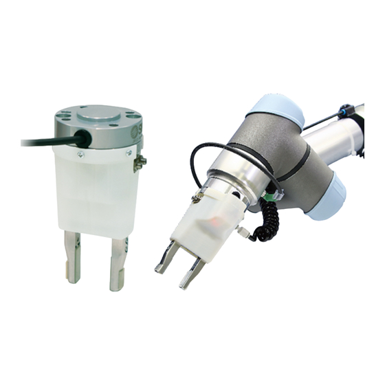
- Page 1 Doc.No.MH-OMY0003 PRODUCT NAME Parallel type Air Gripper MODEL / Series / Product Number JMHZ2-16D-X7400B...
-
Page 2: Table Of Contents
Contents Safety Instructions ..................2 1. List of included items ................. 4 2. Parts description of the air gripper ............5 3. Product Specifications ................6 3-1. Specifications ................... 6 3-2. Gripping force ..................7 3-3. Gripping point ..................8 3-4. -
Page 3: Safety Instructions
Safety Instructions These safety instructions are intended to prevent hazardous situations and/or equipment damage. These instructions indicate the level of potential hazard with the labels of “Caution,” “Warning” or “Danger.” They are all important notes for safety and must be followed in addition to International Standards (ISO/IEC)*1) , and other safety regulations. - Page 4 Safety Instructions Caution The product is provided for use in manufacturing industries. The product herein described is basically provided for peaceful use in manufacturing industries. If considering using the product in other industries, consult SMC beforehand and exchange specifications or a contract if necessary. If anything is unclear, contact your nearest sales branch.
-
Page 5: List Of Included Items
1. List of included items Parallel pin (6×10mm) 1pc. Air Gripper unit 1pcs. Hexagon socket head screw (M6×23) 4pcs. For mounting the product Cross recessed round head screw (M3×6) 3pcs. for mounting the resin cover Resin cover 1pc Polyurethane Tubing (TU0425) 2m... -
Page 6: Parts Description Of The Air Gripper
2. Parts description of the air gripper Auto switch: D-M9P-5 Hexagon socket head Air Gripper: cap screw (M3×7) JMHZ2-16D Miniature Fittings: M-5ALHU-2 Polyurethane Tubing: Metering Valve with Tubing O.D.φ2 Silencer: ASN2-M5-X937 Miniature Fittings: M-5ALHU-2 Adapter plate One-touch Fittings: KQ2S04-M5N Parallel pin: 3 Port Solenoid Valve: V114-5LU Hexagon socket head cap screw... -
Page 7: Product Specifications
3. Product Specifications 3-1. Specifications Specifications Model JMHZ2-16D-X7400B Bore size (mm) Fluid Operating pressure [MPa] 0.1 to 0.7 Ambient and fluid temperature ( -10 to 60 Repeatability (mm) ±0.01 Maximum operating frequency (c.p.m.) Lubrication Non-lube Action Double acting O.D.folding 32.7... -
Page 8: Gripping Force
3-2. Gripping force External gripping state Indication of effective gripping force The gripping force shown in the graph to the right represents the gripping force of one finger when all fingers and attachments are in contact with the workpiece. Gripping Point (mm) Internal gripping state Indication of effective gripping force... -
Page 9: Gripping Point
3-3. Gripping point External gripping state External gripping Gripping Point Internal gripping state Internal gripping The air gripper should be operated so that the workpiece gripping point “L” and the amount of overhang “H” stay within the range shown for each operating pressure given in the graphs to the right. -
Page 10: Dimensions (When The Cover And Attachment Are Mounted)
3-4. Dimensions (when the cover and attachment are mounted) Refer to P12 and P13 for the dimensions of the air gripper and valves. -
Page 11: Connector And Pin Layout
3-5. Connector and pin layout M8 8 Pin connector (Female) Coating Function Description number color White Unused Brown Unused Auto switch Green (finger closing direction) Auto switch Yellow (finger opening direction) Power supply 24 Grey +24V Valve On/Off Pink (finger closing direction) Valve On/Off Blue (finger open direction) -
Page 12: Product Specifications
4. Product Specifications * For detailed specifications not included in this document, please refer to our website (www.smcworld.com) or operation manual. 4-1. Air Gripper Specifications Model JMHZ2-16D Bore size (mm) Fluid Operating pressure [MPa] 0.1 to 0.7 Ambient and fluid temperature ( -10 to 60 Repeatability (mm) ±0.01... -
Page 13: Port Solenoid Valve
4-2. 3 Port Solenoid Valve Specifications. Model V114-5LU Fluid –10 to 50 (No freezing) Ambient and fluid temperature (°C) Response time (DC) (ms) ON: 5 or less OFF: 4 or less Max. operating frequency (Hz) Lubrication Not required Mounting position Unrestricted Impact/Vibration resistance (m/s2) 150/30... -
Page 14: Operating Method / Operation
5. Operating method / operation 5-1. Design ! Warning 1. 1. The product is designed for use only in compressed air systems. Do not operate at pressures or temperatures, etc., beyond the range of the specifications, as this can cause damage or malfunction of the cylinder and other equipment. - Page 15 How to Mount Air Gripper Adjust the robot arm position before mounting so that the mounting is easy. (1) Mounting to the robot arm (2) Mounting of the cover Take care not to get the switch cable Caught when mounting the cover. Hexagon socket head cap screw Maximum tightening Torque : 6.3 (Nm)
- Page 16 (3)Secure the cover (4) Secure the connector *Do not energize while securing the connector. *Check that the connector is not loose cross recessed round head screw (M3X6) maximum tightening torque :0.3Nm (5) Mount the finger attachments. hexagon socket head cap screw maximum tightening torque :0.59Nm Refer to P14, “5-2 Mounting”...
- Page 17 Finger open / close speed adjustment Metering valve Metering valve Finger closing speed adjustment Finger opening speed adjustment Magnified view of the metering valve Adjustment groove (for flat blade screwdriver) * Use a flat blade screwdriver for adjusting the restriction of the metering valves. * Keep the restriction of the 2 metering valves approximately the same.
-
Page 18: Urcap
5-3. URCap Installation and basic setting 1. Installation of URCap (1) Tap the "URCap" menu from the robot settings screen. (2) Insert the USB memory with a cop of the downloaded file into the teaching pad and tap the "+" button. - Page 19 2. Select "SMC Air Gripper Unit" on the "URCaps" menu for basic settings. ① ② ③ ①:“Time to wait for the operation of the gripper to complete”: If the MODE is "OPEN ONLY MODE" or "CLOSE ONLY MODE" (see P.21 for MODE), the delay time between outputting the valve switching signal and the transition of the robot to the next operation can be set.
- Page 20 ②:“Tool weight without work piece”: The mass of the air gripper is entered. If there are tools to attach to the robot arm other than the transferred object, add the mass. The robot performs the optimum operation according to the entered mass.
- Page 21 Program setting Operation program can be set from the “Program” tab. ①:“Select operation” 4 type of operation MODEs are available. 1: “OPEN ONLY MODE” opens the finger. This does not monitor the auto switch signal. 2: Fingers are open when “OPEN AND CHECK SIGNAL MODE” is executed. In this case, after checking the auto switch signal and confirming the reaction, the transition of the operation occurs.
- Page 22 Manual operation From the UR+ icon in the upper right corner of the screen, the manual operation of the gripper can be checked. The gripper operation (open or close) and the auto switch reaction can be checked by tapping the Open/ Close button.
-
Page 23: Air Supply
5-4. Air supply ! Warning 1. Please contact SMC when using the product in applications other than with compressed air. 2. Compressed air containing a large amount of condensate can cause malfunction of pneumatic equipment. An air dryer or water separator should be installed upstream from filters. 3. -
Page 24: Lubrication
5-7. Lubrication ! Caution 1. The non-lube type air gripper is lubricated at the factory and can be used without any further lubrication. If a lubricant is used in the system, use turbine oil Class 1 (with no additive) ISO VG32. Furthermore, once lubrication is applied, it must be continued.
Need help?
Do you have a question about the JMHZ2-16D-X7400B and is the answer not in the manual?
Questions and answers