
Related Manuals for SMC Networks MHM-25D-X7400A


Summary of Contents for SMC Networks MHM-25D-X7400A
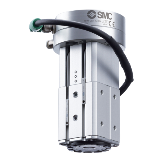
- Page 1 Doc.No.MH*-OMY0015 PRODUCT NAME Magnet Gripper Unit for Collaborative Robots MODEL / Series / Product Number MHM-25D-X7400A...
-
Page 2: Table Of Contents
Contents Safety Instructions ......................- 2 - 1.List of included items ....................- 4 - 2.Parts description of the magnet gripper ..............- 5 - 3.Product Specifications ....................- 6 - 3-1. Specifications .....................- 6 - 3-2. Gripping force .....................- 7 - 3-3. Dimensions ......................- 9 - 3-4. -
Page 3: Safety Instructions
Safety Instructions These safety instructions are intended to prevent hazardous situations and/or equipment damage. These instructions indicate the level of potential hazard with the labels of “Caution,” “Warning” or “Danger.” They are all important notes for safety and must be followed in addition to International Standards (ISO/IEC)*1) , and other safety regulations. - Page 4 Safety Instructions Caution The product is provided for use in manufacturing industries. The product herein described is basically provided for peaceful use in manufacturing industries. If considering using the product in other industries, consult SMC beforehand and exchange specifications or a contract if necessary. If anything is unclear, contact your nearest sales branch.
-
Page 5: List Of Included Items
1.List of included items Positioning pin (6×10) 1pc. For positioning the product. Hexagon socket head cap screw Magnet gripper unit 1pc. (M6×23) 4pcs. For mounting the product. M8 8 Pin connector 1pc. Coil tube for piping (TU0425) 2m - 4 -... -
Page 6: Parts Description Of The Magnet Gripper
2.Parts description of the magnet gripper Auto switch:D-M9P Magnet gripper Adapter Metering Valve with Silencers: ASN2-M5-X937 Hexagon socket head cap screw:M4x35 3-port solenoid valves: V114-5LU One-touch fitting: KQ2S04-M5N Positioning pins:3x6 Hexagon socket head ISO9409-1 cap screws:M4x12 compliant flange Hexagon socket head cap screws:M4x16 M8 8 pin connector cable - 5 -... -
Page 7: Product Specifications
3.Product Specifications 3-1. Specifications Specifications Model No. MHM-25D-X7400A Fluid Operating method Double acting 0.2 to 0.6MPa Operating pressure (MPa) Proof pressure 0.9MPa -10 to 50 Ambient and operating fluid temperature( Workpiece 160N Gripping thickness:2mm Force Workpiece 200N thickness:6mm Residual holding force 0.3 N or less... -
Page 8: Gripping Force
3-2. Gripping force Holding conditions. To lift workpieces vertically, be sure to take into consideration the acceleration rate, air pressure, impact etc., in addition to the mass of the workpieces. Lifting direction Consider the center of gravity of the workpiece to avoid moments being applied the magnet gripper as much as possible. - Page 9 Calculate the required holding force. The holding force graph shows the theoretical value for low carbon steel plate. Holding forces very depending on the material and shape of the workpiece. Please perform a holding test referring to the value selected based on the graph. - 8 -...
-
Page 10: Dimensions
3-3. Dimensions Refer to P12, P13 and P14 for the dimensions of the magnet gripper, valves and auto switches. - 9 -... -
Page 11: Connector And Pin Layout
3-4. Connector and pin layout M8 8 Pin connector(Plug) PIN No. Color Function Explanation White Brown Auto switch Green (For holding position) Auto switch Yellow (For releasing position) Power supply for Gray +24V 24 VDC Valve ON/OFF Pink (For holding position) Valve ON/OFF Blue (For releasing position) -
Page 12: Center Of Gravity
3-5. Center of gravity Flange mounting surface Center of gravity -0.1 -0.5 55.8 - 11 -... -
Page 13: Product Specifications
4.Product Specifications * For detailed specifications not included in this document, please refer to the our website (www.smcworld.com) or operation manual. 4-1. Magnet gripper Specifications Fluid Operating pressure [MPa] 0.2 to 0.6 Operating method Double acting Proof pressure 0.9MPa Ambient and operating fluid -10 to 60 temperature( Workpiece... -
Page 14: 3-Port Solenoid Valve
4-2. 3-port solenoid valve Specifications Model No. V114-5LU Fluid Ambient and operating fluid temperature( -10 to 50 (No freezing) Response time [ms] ON:5 or less OFF:4 or less Minimum operation frequency [Hz] Lubrication Non-lube Mounting orientation Free Impact resistance/Vibration resistance (m/s 150/30 Enclosure rating Dustproof... -
Page 15: Auto Switch
4-3. Auto switch Auto Switch Specifications D-M9P(With indicator light) Auto switch model D-M9P Electrical entry direction In-line Wiring 3-wire Output PNP type Applicable load IC circuit,Relay,PLC Power supply voltage DC5・12・24V(4.5 to 28V) Current consumption 10 mA or less Load voltage Load current 40 mA or less Internal voltage drop... -
Page 16: Operating Method Or Operation
5.Operating method or operation 5-1.Precautions for Design Warning 1.The product is designed for use only in compressed air systems. Do not operate at pressures or temperatures, etc., beyond the range of the specifications, as this can cause damage or malfunction of the cylinder and other equipment. -
Page 17: Installation
5-2. Installation ! Warning 1. Install and operate the product only after reading the Operation Manual carefully and understanding its contents. Also, keep the manual where it can be referred to as necessary. 2. When installing the products, allow access for maintenance. 3. - Page 18 How to Mount Magnet Gripper Adjust the robot arm position before mounting so that the mounting is easy. (1)Mounting to the robot arm (2)Connecting the M8 connector * Do not energize while securing the connector. * Check that the connector is not loose. Hexagon socket head cap screw (M6 x 23) Max.
- Page 19 Operation time adjustment method for holding / releasing the workpiece The piston operation time during workpiece holding / release can be adjusted by adjusting the opening of the metering speed controller valve. Metering valve For adjusting the time to move to the workpiece holding position.
-
Page 20: U R C A P
5-3. U R C a p Installation and basic setting 1. Installation of URCap (1) Tap the "URCap" menu from the robot settings screen. (2) Insert the USB memory with a cop of the downloaded file into the teaching pad and tap the "+" button. - Page 21 2. Select "SMC Magnet Gripper Unit" on the "URCaps" menu for basic settings. ① ② ① “Time to wait for the operation of the gripper to complete” If the NODE is "RELEASE ONLY NODE" or "HOLD ONLY NODE" (see P.21 for NODE), the delay time between outputting the valve switching signal and the transition of the robot to the next operation can be set.
- Page 22 When the box is checked: When workpiece holding or release fails (auto switch detection does not work), the above message pops up and the program stops. In this case, failure signal is output and it can be assigned to the Hold/Release failure signal in ③”Various status signal output to digital output port”.
- Page 23 - 22 -...
- Page 24 Program setting Operation program can be set from the “Program” tab. ①:“Select operation” 4 type of operation NODEs are available. 1: “OPEN ONLY NODE” opens the finger. This does not monitor the auto switch signal. 2: Fingers are open when “OPEN AND CHECK SIGNAL NODE” is executed. In this case, after checking the auto switch signal and confirming the reaction, the transition of the operation occurs.
- Page 25 Manual operation From the UR+ icon in the upper right corner of the screen, the manual operation of the gripper can be checked. The gripper operation (open or close) and the auto switch reaction can be checked by tapping the Open/ Close button. - 24 -...
-
Page 26: Air Supply
5-4. Air supply ! Warning 1. Please contact SMC when using the product in applications other than with compressed air. 2. Compressed air containing a large amount of condensate can cause malfunction of pneumatic equipment. An air dryer or water separator should be installed upstream from filters. 3. -
Page 27: Lubrication
5-7. Lubrication ! Caution 1. The non-lube type air gripper is lubricated at the factory and can be used without any further lubrication. If a lubricant is used in the system, use turbine oil Class 1 (with no additive) ISO VG32. Furthermore, once lubrication is applied, it must be continued. - Page 28 Revision history 4-14-1, Sotokanda, Chiyoda-ku, Tokyo 101-0021 JAPAN Tel: + 81 3 5207 8249 Fax: +81 3 5298 5362 https://www.smcworld.com Note: Specifications are subject to change without prior notice and any obligation on the part of the manufacturer. © 2019 SMC Corporation All Rights Reserved - 27 -...
Need help?
Do you have a question about the MHM-25D-X7400A and is the answer not in the manual?
Questions and answers