
Related Manuals for SMC Networks MHM-25D-X7400A-CRX


Summary of Contents for SMC Networks MHM-25D-X7400A-CRX
- Page 1 Doc.No.MH*-OMY0023-A PRODUCT NAME Magnet Gripper Unit for Collaborative Robots MODEL / Series / Product Number MHM-25D-X7400A-CRX...
-
Page 2: Table Of Contents
Contents Safety Instructions ......................- 2 - 1. List of included items ....................- 4 - 2. Parts description of the magnet gripper ..............- 5 - 3. Product Specifications .....................- 6 - 3-1.How to order ......................- 6 - 3-2. Specifications .....................- 7 - 3-3.Gripping force ......................- 8 - 3-4. -
Page 3: Safety Instructions
Safety Instructions These safety instructions are intended to prevent hazardous situations and/or equipment damage. These instructions indicate the level of potential hazard with the labels of “Caution,” “Warning” or “Danger.” They are all important notes for safety and must be followed in addition to International Standards (ISO/IEC)*1) , and other safety regulations. - Page 4 Safety Instructions Caution The product is provided for use in manufacturing industries. The product herein described is basically provided for peaceful use in manufacturing industries. If considering using the product in other industries, consult SMC beforehand and exchange specifications or a contract if necessary. If anything is unclear, contact your nearest sales branch.
-
Page 5: List Of Included Items
1. List of included items Hexagon socket head cap screw (M6×23) 4pcs. Magnet gripper unit 1pc. Positioning pin (6x10) 1pcs. For mounting the product. For positioning the product. Polyurethane tube for piping φ4 (TU0425BU-100) 2m Conversion cable 1pc. - 4 -... -
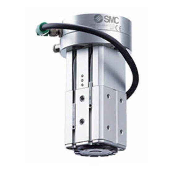
Page 6: Parts Description Of The Magnet Gripper
2. Parts description of the magnet gripper Hexagon socket head cap screws : M6x23 Auto switches: D-M9P Magnet gripper Adapter plate Metering valves Hexagon socket with Silencer: head cap screws ASN2-M5-X937 M4x35 3-port solenoid valves: Positioning pins V114-5LU Hexagon socket head cap screws M4x12 M4x12... -
Page 7: Product Specifications
3. Product Specifications 3-1.How to order - 6 -... -
Page 8: Specifications
3-2. Specifications Specifications Fluid Operating method Double acting Operating pressure (MPa) 0.2 to 0.6MPa Proof pressure 0.9MPa Ambient and operating fluid temperature( -10 to 50 Workpiece 160N thickness:2mm Gripping Force* Workpiece 200N thickness:6mm Residual holding force 0.3 N or less Lubrication Non-lube 590g... -
Page 9: 3-3.Gripping Force
3-3.Gripping force Holding conditions. To lift workpieces vertically, be sure to take into consideration the acceleration rate, air pressure, impact etc., in addition to the mass of the workpieces. Lifting direction Consider the center of gravity of the workpiece to avoid moments being applied the magnet gripper as much as possible. - Page 10 Calculate the required holding force. Workpiece thickness t [mm] The holding force graph shows the theoretical value for low carbon steel plate. Holding forces very depending on the material and shape of the workpiece. Please perform a holding test referring to the value selected based on the graph.
-
Page 11: Dimensions
3-4. Dimensions Refer to P13, P14 and P15 for the dimensions of the magnet gripper, valves and auto switches. - 10 -... -
Page 12: Connector And Pin Layout
3-5. Connector and pin layout Attached cable is fixed to the product. Connect the communication cable correctly. Refer to P.18 for assembling method. M8 8 Pin connector (Plug) PNP output PIN No. Function Explanation Auto switch (For holding workpiece) Auto switch (For releasing workpiece) +24V Power supply for 24 VDC Valve ON/OFF (For holding workpiece) -
Page 13: Centor Of Gravity
3-6. Centor of gravity Flange mounting surface Center of gravity(mm) 42.6 - 12 -... -
Page 14: Product Specifications
4. Product Specifications * For detailed specifications not included in this document, please refer to the our website (www.smcworld.com) or operation manual. 4-1. Magnet gripper Specifications Fluid Operating pressure [MPa] 0.2 to 0.6 Operating method Double acting Proof pressure 0.9MPa Ambient and operating fluid -10 to 60 temperature(... -
Page 15: 3-Port Solenoid Valve
4-2. 3-port solenoid valve Specifications Model No. V114-5LU Fluid Ambient and operating fluid temperature( -10 to 50 (No freezing) Response time [ms] ON:5 or less OFF:4 or less Minimum operation frequency [Hz] Lubrication Not required Mounting orientation Free Impact resistance/Vibration resistance (m/s 150/30 Enclosure rating Dustproof... -
Page 16: Auto Switch
4-3. Auto switch Auto Switch Specifications (With indicator light) D-M9P Auto switch model D-M9P Electrical entry direction In-line Wiring 3-wire Output PNP type Applicable load IC circuit,Relay,PLC Power supply voltage DC5・12・24V(4.5 to 28V) Current consumption 10 mA or less Load voltage DC28V or less Load current 40 mA or less... -
Page 17: Operating Method Or Operation
5.Operating method or operation 5-1.Precautions for Design Warning 1. Confirm the specifications. Products represented in this catalog are designed only for use in compressed air systems (including vacuum).Do not operate at pressures, temperatures, etc., beyond the range of specifications, as this can cause damage or malfunction.(Refer to the specifications.)Please contact SMC when using a fluid other than compressed air (including vacuum).We do not guarantee against any damages if the product is used outside of the specification range. -
Page 18: Installation
5-2. Installation Warning 1. Keep the manual in a safe place for future reference. The product should be mounted and operated only after thoroughly reading the operation manual and understanding its contents. 2. Ensure sufficient space for maintenance activities. When installing the products, allow access for maintenance and inspection. 3. - Page 19 How to Mount Magnet Gripper Adjust the robot arm position before mounting so that the mounting is easy. (2) Connecting the M8 connector (1)Mounting to the robot arm * Do not energize while securing the connector. * Check that the connector is not loose. Hexagon socket head cap screw (M6 x 23) Max.
- Page 20 Operation time adjustment method for holding / releasing the workpiece The piston operation time during workpiece holding / release can be adjusted by adjusting the opening of the metering speed controller valve. Metering valve for adjusting the time to move to the workpiece holding position.
-
Page 21: Crx Plug-In Software
5-3. CRX Plug-in software CRX Plug-in software The CRX plug-in software enables easy connection and mounting of the magnet gripper unit to the robot. Software for compatible robot control devices If the software for the robot control device is V9.40P / 05 version or earlier, update to the latest version V9.40P / 06 version or later before installing the plug-in software. - Page 22 3. Select ”SMC_GrpSwMH.IPL” and tap “Install”. 4. Tap “OK” and install the “SMC Magnet Gripper” Plugin software. 5. After the installation is complete, turn the power back on. - 21 -...
- Page 23 Basic settings Click the hamburger menu icon in the upper left corner of the tablet TP screen. Select the plug-in and. Tap ”SMC Magnet Gripper”, and display the setting screen for the SMC magnet gripper unit SMC. Then, perform the following basic settings. 1.
- Page 24 (4) Select the digital output port. (2) Select box operation is enabled when “Status signal output to digital output port” is enabled. Select the digital output port that outputs the status signal when “Hold / Release success” or “Hold / Release failure” is detected.
- Page 25 Dedicated instruction If the CRX plug-in software is installed successfully, two dedicated instructions HOLD and RELEASE will be added. Test methods: Click the hamburger menu icon in the upper left corner of the tablet TP screen. Select “Teaching”. By tapping the editor, you can check the presence of the "HOLD" and "RELEASE" icons on the programming tab.
- Page 26 Dedicated instruction: HOLD 1. Select the operation. Select the behavior of the HOLD operation. (1) HOLD Put the gripper in HOLD state, the software recognises it as “Hold success” without checking the hold position signal, and proceeds to the next operation. (2) HOLD and monitor signal Put the gripper in HOLD state and wait for a Hold position signal before proceeding to the next action.
- Page 27 Dedicated instruction: RELEASE 1. Select the operation. Select the behavior of the RELEASE operation. (1) RELEASE Put the gripper in RELEASE state, the software recognises it as “RELEASE success” without checking the release position signal, and proceed to the next operation. (2) RELEASE and monitor signal Put the gripper in RELEASE state and waits for a RELEASE position signal before proceeding to the next action.
-
Page 28: Air Supply
5-4. Air supply Warning 1. Type of fluids Please consult with SMC when using the product in applications other than compressed air. 2. When there is a large amount of drainage Compressed air containing a large amount of drainage can cause the malfunction of pneumatic equipment. An air dryer or water separator should be installed upstream from filters. -
Page 29: Operating Environment
5-6. Operating environment Warning 1. Do not use in an atmosphere containing corrosive gases, chemicals, sea water, water, water steam, or where there is direct contact with any of these. Refer to each construction drawing for information on the materials of air grippers. 2. -
Page 30: Replacement Part
6-2. Replacement part 1. Replace the pad using the following procedure. MHM-A2513 Make sure that the pad is correctly in place Remove the old pad Fit the new pad into (The pad is not lifted the groove from the surface) 6-3. - Page 31 Revision history 4-14-1, Sotokanda, Chiyoda-ku, Tokyo 101-0021 JAPAN Tel: + 81 3 5207 8249 Fax: +81 3 5298 5362 https://www.smcworld.com Note: Specifications are subject to change without prior notice and any obligation on the part of the manufacturer. © 2019 SMC Corporation All Rights Reserved - 30 -...
Need help?
Do you have a question about the MHM-25D-X7400A-CRX and is the answer not in the manual?
Questions and answers