Table of Contents
Advertisement
Quick Links
One Technology Way • P.O. Box 9106 • Norwood, MA 02062-9106, U.S.A. • Tel: 781.329.4700 • Fax: 781.461.3113 • www.analog.com
Evaluating the
FEATURES
Full featured evaluation board for the AD4696
2 channels customizable for external connections and
14 channels for on-board dc voltages
On-board reference circuitry
ACE
plugin available for device configuration and
performance evaluation
FMC compatible
System demonstration platform (SDP-H1) compatible
EVALUATION KIT CONTENTS
EVAL-AD4696FMCZ evaluation board
EQUIPMENT NEEDED
System demonstration platform (EVAL-SDP-CH1Z)
Precision analog signal source(s)
12 V switched mode power supply (included with EVAL-SDP-
CH1Z)
USB cable (included with EVAL-SDP-CH1Z)
PC running Windows 7 or higher with USB 2.0 port
ONLINE RESOURCES
AD4696 data sheet
EVAL-AD4696FMCZ user guide
AD4696 ACE plugin evaluation software
PLEASE SEE THE LAST PAGE FOR AN IMPORTANT
WARNING AND LEGAL TERMS AND CONDITIONS.
AD4696
16-Channel, 16-Bit, 1 MSPS Multiplexed SAR ADC
Rev. 0 | Page 1 of 28
EVAL-AD4696FMCZ
GENERAL DESCRIPTION
The EVAL-AD4696FMCZ is designed to demonstrate AD4696
performance and provide access to its many configuration options
via an easy to use ACE plugin graphical interface. The AD4696 is a
16-channel, 16-bit, 1 MSPS, multiplexed successive approximation
register (SAR) analog-to-digital converter (ADC) that enables
high performance data acquisition of multiple signals in a small
form factor. The AD4696 employs easy drive features and on-chip
channel sequencing that simplify hardware and software designs
and allow it to fit into a variety of space constrained precision
multichannel applications.
The EVAL-AD4696FMCZ allows users to quickly evaluate the
performance of the AD4696 with no or minimal hardware
modifications. The hardware includes two externally driven analog
input channels for evaluating ac performance and 14 channels
with dc levels generated on board for evaluating dc and settling
performance. The externally driven channels have configurable
drive circuitry and interface with precision signal generators via
SMA connectors.
The AD4696 ACE plugin communicates with the EVAL-
AD4696FMCZ hardware through the EVAL-SDP-CH1Z controller
board. The software allows AD4696 device configuration via a
register map view and easy to use GUIs. The software also enables
performing analog-to-digital conversions and provides time
and frequency domain analysis tools for quick evaluation of the
AD4696.
More detailed feature descriptions and device specifications are
provided in the AD4696 data sheet and must be consulted in
conjunction with this user guide when using the EVAL-
AD4696FMCZ. Full details on the EVAL-SDP-CH1Z are
available on the SDP-H1 product page.
User Guide
UG-1882
Advertisement
Table of Contents

Related Manuals for Analog Devices EVAL-AD4696FMCZ


Summary of Contents for Analog Devices EVAL-AD4696FMCZ
-
Page 1: Features
EVALUATION KIT CONTENTS multichannel applications. EVAL-AD4696FMCZ evaluation board The EVAL-AD4696FMCZ allows users to quickly evaluate the EQUIPMENT NEEDED performance of the AD4696 with no or minimal hardware modifications. The hardware includes two externally driven analog... -
Page 2: Table Of Contents
General Description ................. 1 Description of Chip View ............14 Revision History ................2 Sequencer Configuration Views ..........14 EVAL-AD4696FMCZ Photograph ..........3 Channel Configuration View............ 17 Evaluation Board Hardware Guide ..........4 Analysis View ................18 Hardware Overview ..............4 Waveform Tab ................ -
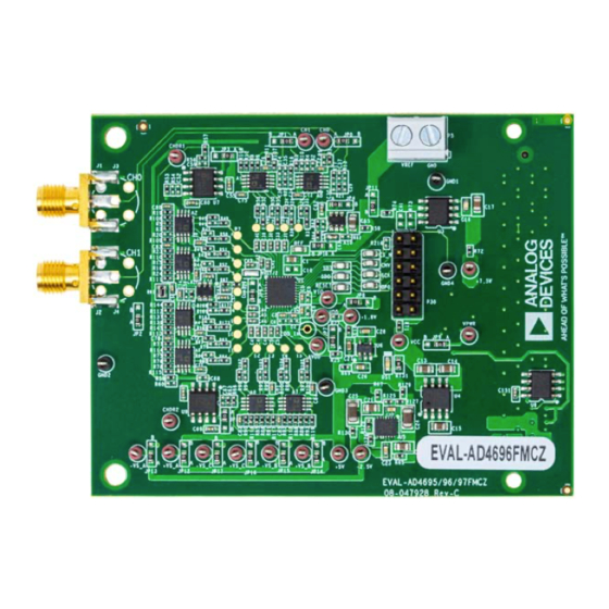
Page 3: Eval-Ad4696Fmcz Photograph
EVAL-AD4696FMCZ User Guide UG-1882 EVAL-AD4696FMCZ PHOTOGRAPH Figure 1. Rev. 0 | Page 3 of 28... -
Page 4: Evaluation Board Hardware Guide
The amplifiers driving Channel IN2 to Channel IN15 are driven device. to dc voltages by on-board amplifiers and user configurable The EVAL-AD4696FMCZ is a quick start evaluation platform that resistor dividers (see the Configuring DC Channels (IN2 showcases the performance of the AD4696 with no or minimal Through IN15) section). - Page 5 A0 by default. in the range from 0 V to V . For this reason, additional Table 2. Resistor Dividers for Setting CHDR1 and CHDR2 amplifiers are provided on the EVAL-AD4696FMCZ hardware, Signal Reference Designators Default Values...
- Page 6 Resistor Channel Default Voltage network from the selected VREF source. JP6 selects whether the COM pin is connected directly to the EVAL-AD4696FMCZ ground (for example, 0 V) or the V /2 V output of A8. Ensure 2.5 V that JP6 is configured appropriately for the channel configuration settings selected via the AD4696 evaluation software.
-
Page 7: Reference
POWER SUPPLIES different sets of amplifiers, as shown in Table 6. The EVAL-AD4696FMCZ is designed to operate from a 12 V Power Options for the AD4696 supply (labeled VPWR_12V) and a 3.3 V supply (labeled... -
Page 8: Digital Interface
0. It is worth noting that because the internal LDO regulator of FMC connector (P1). The software and hardware are designed the AD4696 is enabled by default, when the EVAL-AD4696FMCZ to quickly and easily connect and enable evaluation of the AD4696. -
Page 9: Link Configuration Options
LINK CONFIGURATION OPTIONS Take care before applying power and signals to the EVAL- functions on the EVAL-AD4696FMCZ hardware, and indicates the default positions in which the links are set as manufactured. AD4696FMCZ to ensure all solder link positions are set as required by the operating mode. -
Page 10: Getting Started
Warning The ACE evaluation software and drivers must be installed before connecting the EVAL-AD4696FMCZ and the SDP-H1 to the USB port of the PC to ensure that the evaluation system is correctly recognized when it is connected to the PC. - Page 11 ACE plugin, perform click Finish to complete. the following steps: From the Start menu, select All Programs > Analog Devices > ACE > ACE.exe, which brings up the window shown in Figure 13. To install the AD4696 ACE plugin, click Plug-in Manager on the left of the ACE main window, as shown in Figure 10.
- Page 12 UG-1882 EVAL-AD4696FMCZ User Guide Figure 10. Selecting Plug-in Manager Figure 11. Installing AD4696 ACE Plugin Figure 12. Updating AD4696 ACE Plugin Rev. 0 | Page 12 of 28...
-
Page 13: Evaluation Hardware Setup Procedure
EVAL-AD4696FMCZ User Guide UG-1882 EVALUATION HARDWARE SETUP PROCEDURE Verifying Hardware Connection To verify the EVAL-AD4696FMCZ is properly connected to the When using the AD4696 ACE plugin, the SDP-H1 is required PC, take the following steps: to interface between the EVAL-AD4696FMCZ hardware and the PC. -
Page 14: Evaluation Software Operation
(see the Analysis View section). The Proceed to Memory Map button opens the AD4696 From the Start menu, select All Programs > Analog Devices Memory Map view (see the Memory Map View section). > ACE > ACE.exe, which opens the window shown in Figure 13. - Page 15 EVAL-AD4696FMCZ User Guide UG-1882 Figure 13. Software Start Window Figure 14. Evaluation Board View Figure 15. Chip View Rev. 0 | Page 15 of 28...
- Page 16 UG-1882 EVAL-AD4696FMCZ User Guide Figure 16. Standard Sequencer View Figure 17. Advanced Sequencer View For example, in Figure 16, each enabled channel has an effective slot using the slot assignment dropdown menus. Click Apply sample rate of FSR/4 because there are four channels enabled in Changes to configure the connected device accordingly.
-
Page 17: Channel Configuration View
EVAL-AD4696FMCZ User Guide UG-1882 CHANNEL CONFIGURATION VIEW The controls that are visible in the All Channel Controls tab vs. the controls visible in the Controls for Channel tab depends on AD4696 ACE plugin includes a channel configuration view the active sequencer mode (standard sequencer vs. advanced... -
Page 18: Analysis View
UG-1882 EVAL-AD4696FMCZ User Guide All Channel Controls The Hysteresis Value text box accepts 12-bit hexadecimal values between 0x000 and 0xFFF. The value entered in this text box is The All Channel Controls tab appears at the top of the Channel written to the hysteresis bit field in the corresponding Configuration view as shown in Figure 18 and Figure 19. - Page 19 EVAL-AD4696FMCZ User Guide UG-1882 Figure 21. Histogram Tab Figure 22. FFT Tab Capture Pane Clicking the Go to Sequencer button opens either the standard sequencer view or the advanced sequencer view based on the General Capture Settings value selected in the Sequencer Mode dropdown menu.
-
Page 20: Waveform Tab
UG-1882 EVAL-AD4696FMCZ User Guide Run Once Waveform Graph The data waveform graph shows each successive sample of the Click Run Once to start a data capture at the sample rate specified ADC output. The user can zoom and pan the waveform using in the Throughput (kSPS) box for the number of channel the embedded waveform tools. - Page 21 EVAL-AD4696FMCZ User Guide UG-1882 Apply Selected Software Defaults Click Apply Selected to write data only to selected registers. To Click Software Defaults to update the bit fields in the memory select a register, click the desired register in the memory map view.
-
Page 22: Evaluation Board Schematics And Artwork
RCU-0C RCU-0C RCU-0C RCU-0C RCU-0C RCU-0C IN12 IN13 CS_N RESET IN14 IN15 IN10 IN11 Figure 24. EVAL-AD4696FMCZ Top Level Schematic POWER INDICATOR LED 12V/7.5V LDO ADR4550 5.0V REFERENCE ADR4550BRZ R131 5V_REF R123 +7.5 V VPWR_12V VPWR +7.5 V SML-D12M8W VOUT... - Page 23 AGND AGND AGND AGND -INB OUTB R111 CHDR1 -INB +INB OUTB CHDR1 R106 LT6237HMS8#TRPBF +INB 180PF LT6237HMS8#TRPBF 180PF AGND AGND AGND AGND AGND AGND Figure 26. EVAL-AD4696FMCZ Driver Amplifier Schematic, IN0 to IN7 Rev. 0 | Page 23 of 28...
- Page 24 +INB LT6237HMS8#TRPBF 180PF LT6237HMS8#TRPBF 180PF AGND AGND AGND AGND AGND AGND Figure 27. EVAL-AD4696FMCZ Driver Amplifier Schematic, IN8 to IN15 ON-BOARD REFERENCE BUFFER R120 VREF/2 DIVIDER CIRCUIT REFERENCE SOURCE OPTIONS ON-BOARD OR EXTERNAL REFERENCE +VS_C +VS_C 3PINJUMPER_0603 JP11 REF_EXT 0.1UF...
- Page 25 JP13 JP15 JP17 -2.5 V -2.5 V -2.5 V -VS_A -VS_B -VS_C AGND AGND AGND Figure 29. EVAL-AD4696FMCZ Amplifier Power Supply Jumper Selection Schematic DIGITAL HOST CONNECTIONS FMC 160-PIN CONNECTOR EEPROM +3.3V_AUX E0VCC WC_N C151 0.1UF CS_N AGND AGND M24C02-RMN6TP...
- Page 26 UG-1882 EVAL-AD4696FMCZ User Guide Figure 31. EVAL-AD4696FMCZ Silkscreen, Top Assembly Figure 32. EVAL-AD4696FMCZ, Top Layer Figure 33. EVAL-AD4696FMCZ Layer 2, Ground Rev. 0 | Page 26 of 28...
- Page 27 EVAL-AD4696FMCZ User Guide UG-1882 Figure 34. EVAL-AD4696FMCZ Layer 3, Power Figure 35. EVAL-AD4696FMCZ Bottom Layer Rev. 0 | Page 27 of 28...
- Page 28 By using the evaluation board discussed herein (together with any tools, components documentation or support materials, the “Evaluation Board”), you are agreeing to be bound by the terms and conditions set forth below (“Agreement”) unless you have purchased the Evaluation Board, in which case the Analog Devices Standard Terms and Conditions of Sale shall govern. Do not use the Evaluation Board until you have read and agreed to the Agreement.
Need help?
Do you have a question about the EVAL-AD4696FMCZ and is the answer not in the manual?
Questions and answers