Table of Contents
Advertisement
Quick Links
Evaluation of the ADRF5301, Silicon SPDT Switch, Reflective, 37 GHz to 49 GHz
FEATURES
Full-featured evaluation board for the
►
Simple connection to test equipment
►
On-board through line for calibration
►
EQUIPMENT NEEDED
DC power supply
►
Network and spectrum analyzer
►
GENERAL DESCRIPTION
The ADRF5301-EVALZ is designed to evaluate the features and
performance of the
ADRF5301
which has a frequency range of 37 GHz to 49 GHz. The
ADRF5301-EVALZ (see
Figure
connector.
For full details, see the
ADRF5301
consulted in conjunction with this user guide when using the
ADRF5301-EVALZ.
PLEASE SEE THE LAST PAGE FOR AN IMPORTANT
WARNING AND LEGAL TERMS AND CONDITIONS.
ADRF5301
silicon, SPDT, reflective switch,
1) is populated with a 2.4 mm
data sheet, which must be
User Guide | EVAL-ADRF5301
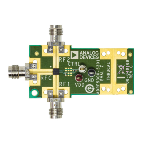
EVALUATION BOARD PHOTOGRAPH
Figure 1. Evaluation Board Photograph
UG-2061
Rev. 0 | 1 of 7
Advertisement
Table of Contents

Subscribe to Our Youtube Channel
Related Manuals for Analog Devices EVAL-ADRF5301


Summary of Contents for Analog Devices EVAL-ADRF5301
-
Page 1: Features
User Guide | EVAL-ADRF5301 UG-2061 Evaluation of the ADRF5301, Silicon SPDT Switch, Reflective, 37 GHz to 49 GHz FEATURES EVALUATION BOARD PHOTOGRAPH Full-featured evaluation board for the ADRF5301 ► Simple connection to test equipment ► On-board through line for calibration ►... -
Page 2: Table Of Contents
User Guide EVAL-ADRF5301 TABLE OF CONTENTS Features..............1 RF Inputs and Outputs........3 Equipment Needed..........1 Power Supply and Control Inputs.......4 General Description..........1 Test Procedure............5 Evaluation Board Photograph........1 Evaluation Board Schematic and Assembly Evaluation Board Hardware........3 Diagram............... 6 Overview............3 Ordering Information..........7... -
Page 3: Evaluation Board Hardware
User Guide EVAL-ADRF5301 EVALUATION BOARD HARDWARE OVERVIEW RF INPUTS AND OUTPUTS The ADRF5301-EVALZ is a connectorized evaluation board assem- The RF input and output ports (RFC, RF1, and RF2) are connected bled with the ADRF5301 device and application circuitry. All compo- through 50 Ω... -
Page 4: Power Supply And Control Inputs
User Guide EVAL-ADRF5301 EVALUATION BOARD HARDWARE POWER SUPPLY AND CONTROL INPUTS Because the ADRF5301 incorporates a negative voltage generator (NVG) to operate with a single positive supply of 3.3 V applied to the VDD pin, only one power supply is needed to power up the ADRF5301-EVALZ. -
Page 5: Test Procedure
User Guide EVAL-ADRF5301 TEST PROCEDURE The ADRF5301-EVALZ is shipped assembled and tested. Figure ADRF5301 can be configured in different modes by connecting shows a basic setup diagram to measure the scattering parame- the CTRL test point to 3.3 V or 0 V, as shown in Table ter response of the ADRF5301. -
Page 6: Evaluation Board Schematic And Assembly Diagram
User Guide EVAL-ADRF5301 EVALUATION BOARD SCHEMATIC AND ASSEMBLY DIAGRAM Figure 5. ADRF5301-EVALZ Schematic Figure 6. ADRF5301-EVALZ Assembly Diagram analog.com Rev. 0 | 6 of 7... -
Page 7: Ordering Information
Evaluation Board until you have read and agreed to the Agreement. Your use of the Evaluation Board shall signify your acceptance of the Agreement. This Agreement is made by and between you (“Customer”) and Analog Devices, Inc. (“ADI”), with its principal place of business at Subject to the terms and conditions of the Agreement, ADI hereby grants to Customer a free, limited, personal, temporary, non-exclusive, non-sublicensable, non-transferable license to use the Evaluation Board FOR EVALUATION PURPOSES ONLY.
Need help?
Do you have a question about the EVAL-ADRF5301 and is the answer not in the manual?
Questions and answers