
Related Manuals for vacuubrand MV 10 VARIO select


Summary of Contents for vacuubrand MV 10 VARIO select
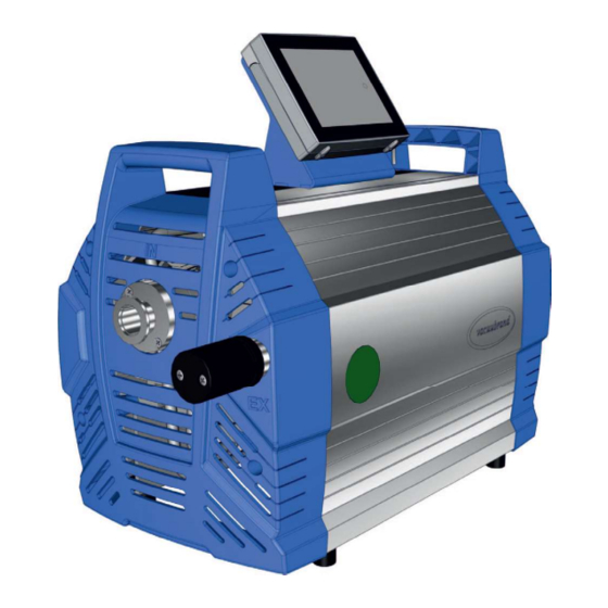
- Page 1 Technology for Vacuum Systems IAPHRAGM PUMP MV 10 VARIO select MD 12 VARIO select ME 16 VARIO select Instructions for use Original instructions OI no.: 20901121...
- Page 2 VACUUBRAND GMBH + CO KG Alfred-Zippe-Str. 4 97877 Wertheim GERMANY Phone: Email: info@vacuubrand.com Web: www.vacuubrand.com Thank you for purchasing this product from VACUUBRAND GMBH + CO KG . You have chosen a modern and techni- cally high quality product. 20901121_EN_Mx10+12+16_VARIO_Vsel_V1.0_020818...
-
Page 3: Table Of Contents
TABLE OF CONTENT Introduction User information ....... . . 1.2 About this document......6 1.2.1 Manual structure . - Page 4 Commissioning (operation) ............... . . see description of controller).
-
Page 5: Introduction
The illustrations in this manual are only intended to facilitate comprehension. continuous product improvement. Copyright The content of this manual is protected by copyright. Only copies for internal use are allowed, e.g., for professional training. © VACUUBRAND GMBH + CO KG 20901121_EN_Mx10+12+16_VARIO_Vsel_V1.0_020818... -
Page 6: About This Document
If your manual is incomplete, you can request a replace ment. Alternatively, you can use our download portal: www.vacuubrand.com You are welcome to contact us at any time in writing or by tele When contacting our Service Department, please have the... -
Page 7: Display Conventions
1.2.2 Display conventions Warning levels DANGER Display conventions Indicates an imminent hazardous situation. Disregarding the situation will result in serious and even fatal injury or death. tions! WARNING Indicates a potentially hazardous situation. Disregarding the situation could result in serious, even fatal injury or massive damage to property. - Page 8 1.2.3 Symbols and icons This manual uses symbols and icons. Safety symbols indicate Safety symbols Explanation of safety symbols hazards to human health. prohibition sign. Warning warning sign. Danger: electricity. Danger: hot surface Disconnect power plug. mandatory sign. Wear chemical resistant Wear protective goggles.
- Page 9 1.2.4 Handling instructions (action steps) Instructions Display of operating steps Perform the step described. Result of action Instructions 1. First step 2. Next step Result of action Perform the steps in the order described. 1.2.5 Abbreviations abs. absolute Abbreviations Interior diameter Nominal diameter ECTFE e.g.
- Page 10 VACUU·SELECT controller and ® VACUU·SELECT Sensor. ® VACUU·BUS Bus system from VACUUBRAND for com ® munication between peripheral devices with VACUU·BUS ® enabled gauges and control lers. The maximum permissible cable length is VACUU·BUS Address which enables the VACUU·BUS...
-
Page 11: Safety Information
Safety information The information in this chapter must be observed by everyone The safety instructions are valid for the complete life cycle of the product. 2.1 Usage 2.1.1 Intended use A diaphragm pump of the Mx 1x VARIO select product series is Intended use a vacuum system consisting of a vacuum pump, controller and sensor to create and control rough vacuum in designated systems,... -
Page 12: Improper Use
2.1.2 Improper use Incorrect use or any application which does not correspond to the Improper use technical data may result in injury or damage to property. Improper use includes: using the product contrary to its intended use, by the company, operation under inadmissible environmental and operating condi tions, operation despite obvious faults or defective safety devices,... -
Page 13: Obligations
pumping oxidizing and pyrophoric substances, liquids or solids, Foreseeable misuse pumping hot, unstable, or explosive media, pumping substances which may react explosively under impact and/or elevated temperature without an air supply. IMPORTANT! must be allowed to enter the equipment. 2.2 Obligations 2.2.1 Operator obligations Operator obligations applies in particular to connection, assembly and maintenance... - Page 14 Responsibility matrix Responsibility Responsible Task (Job) Operator Specialist Assignment Matrix specialist Installation Initial use Operation Error report Remedy Maintenance Repair Repair order Shutdown Decontamination see also website: VACUUBRAND > Support > Instructions for repair 20901121_EN_Mx10+12+16_VARIO_Vsel_V1.0_020818...
- Page 15 2.4 General safety information Products from VACUUBRAND GMBH + CO KG are subject Quality standards to stringent quality testing with regard to safety and operation. safety Each product undergoes a comprehensive test program prior to delivery. 2.4.1 Protective clothing No special protective clothing is required to operate the vacuum Protective clothing place.
- Page 16 2.4.3 Laboratory and working materials DANGER Hazardous substances could be discharged at the outlet. During aspiration, hazardous, toxic substances at the outlet can get into the ambient air. Observe the national regulations for safe handling of hazardous substances. Please note that residual process media may pose a danger to people and the environment.
- Page 17 2.4.4 Eliminate sources of danger Take mechanical stability into account The high compression ratio of the pump may result in a higher Note mechanical load pressure at the outlet than the mechanical stability of the system capacity allows. exit freely. silencer.
- Page 18 Prevent foreign bodies inside the pump Particles, liquids and dust must not get inside the vacuum pump. Observe vacuum pump dimensioning Do not pump any substances which could form deposits inside the vacuum pump. Replace porous vacuum hoses without delay. Hazards during venting Depending on the application, explosive mixtures can form or oth Hazards when...
- Page 19 Risk of burns due to hot surfaces or overheating The surface of the vacuum pump can reach operating tempera Surface tempera tures tures > 70 °C, in particular when pumping heated media. The sur face temperature of the silencer in particular might be elevated in Avoid direct contact with the surface.
- Page 20 Keep signs legible Keep labels and information symbols and warning labels always Signs and labels in a well readable condition: Warning signs and notice labels Motor data and rating plates 2.5 Motor protection The pump motor has a temperature sensor on the circuit board as Overheating protection, overload protection.
-
Page 21: Atex Equipment Category
2.6 ATEX equipment category Installation and potentially explosive atmospheres Installation and operation in areas where potentially explo- sive atmospheres can develop to a hazardous degree is not permitted. ATEX approval only applies to the internal, wetted parts of the of the product, not to its surroundings. ATEX equipment labeling Vacuum equipment labeled with has ATEX approval in line... -
Page 22: Proper Disposal
2.7 Proper disposal NOTICE Risk of environmental damage due to incorrect disposal of the product. Do not dispose your product in household waste! Electronic components are subject to hazardous waste treat Observe the national regulations for safe disposal and envi ronmental protection. -
Page 23: Product Description
Product description The diaphragm pumps described essentially consist of a diaphragm pump with VARIO drive, a VACUU·SELECT vacuum ® ® controller and a VACUU·SELECT Sensor ® 3.1 Schematic design Side and front view Meaning VACUU·SELECT Sensor, to be mounted externally on suction ®... - Page 24 The diaphragm pumps differ in the internal connection of the pump heads. Diaphragm pumps Mx 1x VARIO select Diaphragm pump Pump heads Stages Stages of diaphragm pump ME 16 VARIO select MD 12 VARIO select MV 10 VARIO select 20901121_EN_Mx10+12+16_VARIO_Vsel_V1.0_020818...
-
Page 25: Installation And Connection
Installation and connection 4.1 Transport Products from VACUUBRAND product for safe transport. returning the product for repair. Goods arrival Immediately report any transport damage in writing to the sup plier. Unpacking Example Diaphragm pump in with enclosed 20901121_EN_Mx10+12+16_VARIO_Vsel_V1.0_020818... -
Page 26: En_Mx10+12+16_Vario_Vsel_V1.0
Example diaphragm pump Please note that a dia- phragm pump can weigh approx. 28 kg. We recom mend using a lifting aid. dles. 4.2 Installation NOTICE Condensate can damage the electronics. A large temperature difference between the storage location and the installation location can cause condensation. After goods receipt or storage, allow your vacuum device to Check installation conditions The device is acclimatized. - Page 27 Installing the vacuum pump face. Example minimum distances in laboratory furniture When installing in lab furniture, maintain a minimum distance IMPORTANT! tion, especially in closed housings. Observe limitations of use Observe limitation of Limitation of use Ambient temperature 10– Max. altitude 2000 m above sea level above NHN...
- Page 28 4.3 Controller base closed separately. Before installation, the base can be mounted on the pump and the controller clipped into place. Alternatively, the controller can be clipped into a recess in the lab Mount the base Mount the base to the diaphragm pump 1.
- Page 29 4.4 Connection The diaphragm pumps have a vacuum connection and an outlet examples below. 4.4.1 Assemble silencer (EX) As standard the diaphragm pumps are equipped with a silencer at Silencer at the outlet EX WARNING Risk of bursting due to internal overpressure at the silencer.
- Page 30 Assemble the silencer Assemble silencer the pump. Silencer assembled. 4.4.2 Vacuum connection (IN) CAUTION Flexible vacuum hoses can contract during evacuation. Fix the vacuum hose to the connections. Secure connected components. NOTICE Foreign bodies in the suction line can damage the vacuum pump.
- Page 31 IMPORTANT! the required vacuum range. Keep hose lines as short as possible. pump. Connect the vacuum hose Example Vacuum connection at the inlet IN 2. Attach the vacuum hose to pump inlet (b) with a centering ring and clamping ring. Observe the following points for optimum results: Keep the vacuum line as short as you can with as large a Alternatively, you can connect a vacuum hose via an...
- Page 32 4.4.3 Outlet connection (EX) As standard the diaphragm pumps are equipped with a si see accessories in 8.2 Ordering information on page WARNING Risk of bursting due to overpressure inside the outlet line. Inadmissibly high pressure in the outlet line can cause the vacuum pump to burst or damage seals.
- Page 33 Connect the exhaust gas hose (optional) The following example describes the connection via hose nozzle. Example Exhaust gas connec tion at the outlet EX (c), d 2. Push the exhaust gas hose (d) onto the hose nozzle and lay outlet hose, e.g., with a hose clip. 20901121_EN_Mx10+12+16_VARIO_Vsel_V1.0_020818...
- Page 34 4.4.4 Connect venting valve (optional) DANGER Risk of explosion due to venting with air. Depending on the application, venting can cause explo sive mixtures to form or other hazardous situations to arise. Never vent processes with air which could form an explosive mixture.
- Page 35 4.4.5 Electrical connection Electrical connection of the pump Example Electrical connection diaphragm pump 1. Plug the connector (e) on the power cable into the power con nection of the vacuum pump. 2. Plug power plug (f) into the power outlet. Vacuum pump electrically connected.
- Page 36 IMPORTANT! power connection. 20901121_EN_Mx10+12+16_VARIO_Vsel_V1.0_020818...
-
Page 37: Commissioning (Operation)
Commissioning (operation) 5.1 Switch on Switch pump on Switch pump on (a) on – switch position I. 2. Press ON/OFF button (b) on the controller. The start screen is displayed. with the operating elements in the controller display. 5.2 Operation Apart from the chapters Switch on and Switch off, this manual de Operation with vacuum controller... - Page 38 Process screen Process screen vacuum controller Status bar Analogue pressure display – pressure curve Digital pressure reading – pressure value Process screen with context features Screen navigation Operating elements for control Operating elements Button Vacuum controller Function operating elements active Start Start application –...
- Page 39 5.2.1 Operation ( see description of controller) Start the vacuum controller Start Stop the vacuum controller Stop Venting (option) Venting 20901121_EN_Mx10+12+16_VARIO_Vsel_V1.0_020818...
- Page 40 5.3 Shutdown (switch off) Take the pump out of operation 1. Stop the process. Switch pump off 2. Disconnect the pump from the apparatus. inlet. vacuum pump. IMPORTANT! Prevent deposits and rinse condensate out of the pump. (a) off – switch position 0. Pump switched off.
- Page 41 5.4 Storage Store the vacuum pump 2. Recommendation: Perform a preventive maintenance before storing the vacuum pump. This is especially important if it ran caps. dust; enclose desiccants if necessary. 5. Store the vacuum pump in a cool, dry location. If damaged parts are stored for operational reasons, these should IMPORTANT! not ready for use.
- Page 42 20901121_EN_Mx10+12+16_VARIO_Vsel_V1.0_020818...
-
Page 43: Troubleshooting
Operator not pass on in connection and measured val connection or cables cables to the con defective or not con troller. nected. Sensor defective. Replace defective Specialist components. 1 -> Phone: +49 9342 808-5660, fax: +49 9342 808-5555, service@vacuubrand. 20901121_EN_Mx10+12+16_VARIO_Vsel_V1.0_020818... - Page 44 Error Possible cause Remedy Personnel Remedy Venting valve No voltage applied. Specialist in connection and not switch connection or cables cables to the con defective or not con troller. nected. Venting valve dirty. valve. Perform compo nent detection in – see: Main menu/ Administration/ If necessary, use another external...
- Page 45 Error Possible cause Remedy Personnel Remedy No or very little Operator suction power line or in the appara and apparatus for tus. Vacuum line too long Use a shorter vac Operator uum line with a small. tion. Allow vacuum Operator the vacuum pump.
- Page 46 Error Possible cause Remedy Personnel No silencer or hose Operator hose and install noises mounted at the outlet. correctly. Outlet line open. connections. let line to an extrac tion system or fume hood. Ball bearing defec Service the vacuum Specialist tive.
-
Page 47: Cleaning And Maintenance
Cleaning and maintenance WARNING Danger due to electrical voltage. Switch the device off before cleaning or maintenance Risk from contaminated parts. Pumping hazardous media can result in hazardous substances adhering to internal parts of the pump. Wear your personal protective equipment, e.g., pro tective gloves, eye protection and, if necessary, re spiratory protection. - Page 48 7.1 Information on service work Recommended maintenance intervals Maintenance intervals* if required 15000 h Replace diaphragms Replace valves * Recommended maintenance interval after hours of operation and under nor- mal operating conditions; depending on the environment and area of applica- tion, we advise performing cleaning and maintenance as needed.
- Page 49 Tools needed for maintenance Example Tool Tool Size Service kit #20696827 Diaphragm wrench #20636554 SW66 Flat nose pliers Flat-head screwdriver Open hose clamps Size 1 Phillips screwdriver Size 1 Size 2 Hex key Torque wrench, adjustable 2–10 Nm 20901121_EN_Mx10+12+16_VARIO_Vsel_V1.0_020818...
-
Page 50: 7.2.1 Diaphragm Pump
7.2 Cleaning IMPORTANT! This chapter does not contain descriptions for decontamina tion of the product. This chapter describes simple measures for cleaning and care. Before cleaning, switch off the diaphragm pump. 7.2.1 Diaphragm pump Clean the surfaces mend using water or mild soapy water to moisten the cloth. 7.2.2 Clean or replace molded PTFE hoses of the diaphragm pump, including the hoses. - Page 51 7.3 Diaphragm pump maintenance 7.3.1 Maintenance items Servicing positions Example Diaphragm pump, front, view Maintenance items and sequence Meaning Bottom pump head pair Top pump head pair Right pump head pair Observe the recommended sequence of maintenance steps according to the table: Then change the inlet/outlet valves.
- Page 52 7.3.2 Preparation see also chapter: 4.3 Controller base on page 28 Disassemble the device and housing sections Disassemble the front housing section 1. Switch the diaphragm pump off 2. Unscrew the silencer from the and unplug the power plug. outlet. 4.
- Page 53 6. Remove the housing section and set it aside. Remove the side panel 1. Unscrew the 2 outer screws 2. Unscrew the right screw from from the side panel retain the side panel retaining plate at Remove the left side panel 3.
- Page 54 pump. Place the pump care fully on its other side. Remove the right side panel pump. 20901121_EN_Mx10+12+16_VARIO_Vsel_V1.0_020818...
- Page 55 7.3.3 Replacing the diaphragms and valves Exploded drawing of pump head (example) pump head Valve maintenance Housing cover Valves Diaphragm maintenance Head cover Double diaphragm, 2 diaphragms per pump head Diaphragm support disc 20901121_EN_Mx10+12+16_VARIO_Vsel_V1.0_020818...
- Page 56 Bottom pump head pair Example Bottom pump head pair 1. Turn the pump to bring the bot 2. Pull off the molded hoses. tom pump head pair to the top. Open the hose clips on the size 1. 4. Remove the housing cover. screws from the housing cover.
- Page 57 Remove valves and valves. 8. Remove the head covers. 20901121_EN_Mx10+12+16_VARIO_Vsel_V1.0_020818...
- Page 58 Replace the diaphragms Example Replacing the diaphragms either side. phragm wrench on the dia phragm support disc and unscrew the assembly with the diaphragm wrench attached. 4. If the spacer discs adhere to all the parts, out of the vacuum the connecting rod, remove pump.
- Page 59 Example Replacing the diaphragms 5. Pull out the diaphragm clamp 6. Place the new diaphragm over ing disc and remove the used the square head of the clamp diaphragm. ing disc. IMPORTANT! Double diaphragm comprising 2 single diaphragms. Use the dia phragms only in pairs.
- Page 60 10. Initially tighten the assembly and place all the components with the diaphragm wrench by carefully on the connecting hand. rod thread. 11. Then position a torque ing the next diaphragm. on the diaphragm wrench and tighten the assembly to 6 Nm.
- Page 61 Insert valves Example Insert valves and 1. Place the head covers onto the diaphragms. Pay attention grooves. to the correct orientation of the Insert the new valves. Pay head covers. attention to the correct orienta tion of the valves. 4. Put the housing cover on prop align the head covers.
- Page 62 7. Secure the hose clips on the 8. Turn the pump to bring the top pump head pair to the top. pliers. Support the pump, e. g., with rigid foam. Maintain the top, Follow the same procedure to replace the diaphragms and valves right and left pump Bottom pump of the top pump head pair as described for the...
- Page 63 Assemble the device and housing sections Mount the side panel 1. Place the side panel on the pump. 3. Turn the pump to the top. 4. Place the side panel on the pump. 6. Secure the cable in the rear recess.
- Page 64 8. Place the rear housing section. panel retaining plate at the 9. Wind in the screws of the Prior to mounting the front housing section the suction/pressure distributor of the pumps MD 12 and MV 10 VARIO select has to be maintained. 20901121_EN_Mx10+12+16_VARIO_Vsel_V1.0_020818...
- Page 65 Suction/pressure distributor maintenance Maintenance of This description only applies to diaphragm pumps MD 12 suction/pressure and MV 10 VARIO select. distributor Exploded drawing of suction/pressure distributor (example) Example Pressure relief valve Maintenance overpressure relief valve + O-ring 3 Hose nozzle...
- Page 66 Replace pressure relief valve + O-ring Replace pressure relief valve and 1. Place the vacuum pump on 2. Only open the hose clips above a clean, stable surface as shown. head screwdriver size 1. 3. Remove the molded hoses 4. Unscrew the screws of the out one by one from the hose let holder.
- Page 67 pressure relief valve and the necessary. head screwdriver. Bottom 9. Place the new pressure relief 10. Place the suction distributor valve on the clean surface. with screws and outlet holder Ensure the pressure relief valve onto the pressure distributor. is positioned correctly on the pressure distributor.
- Page 68 14. Secure the hose clips on the into place on the hose noz zles. nose pliers. Assemble the device and housing sections Assemble the device and housing sections 1. Insert the bar into the groove 2. Wind in the 2 outer screws of between the side panels.
- Page 69 5. Screw the silencer in the 6. Secure the controller on the thread at the outlet.. diaphragm pump and connect all cables. 7. Plug in the power plug. If maintenance work has been completed in full: Diaphragm pump is ready to be returned to use. If not reconnected: Diaphragm pump is ready for storage.
-
Page 70: Appendix
Appendix 8.1 Technical information Diaphragm pump series ME 16 VARIO select MD 12 VARIO select MV 10 VARIO select 8.1.1 Technical data Technical data Ambient conditions Ambient temperature, max. 10– Storage/transport temperature 2000 m Max. altitude above sea level above NHN... -
Page 71: En_Mx10+12+16_Vario_Vsel_V1.0
Number of cylinders/stages MD 12 VARIO select Max. pumping speed 16 m /h Ultimate vacuum, abs. 1.1 Torr Number of cylinders/stages MV 10 VARIO select Max. pumping speed Ultimate vacuum, abs. 0.2 Torr Number of cylinders/stages Max. inlet pressure, abs. 1,1 bar Max. - Page 72 21.7 in x 10.2 in x 17.7 in Weight* MD 12 VARIO select 21.7 in x 10.2 in x 17.7 in Weight* MV 10 VARIO select 21.7 in x 10.2 in x 17.7 in Weight* * without cable Other information Sensor type...
-
Page 73: 8.1.2 Wetted Materials
8.1.2 Wetted materials Component Wetted materials Pump Wetted materials Housing cover Aluminium alloy Head cover Diaphragm clamping disc Diaphragm Valves Stainless steel Hoses PTFE Inlet Aluminium alloy Suction/pressure distributor Aluminium alloy Outlet Silencer Anodized aluminum / PTFE / PTFE carbon reinforced / spring steel VACUU·SELECT Sensor Vacuum sensor Measurement chamber... - Page 74 8.1.3 Rating plate Data on rating plate number on the rating plate. When contacting our Service Department, please provide the type and serial number from the rating plate. This will your device. Diaphragm pump rating plate, general Example rating plate Product series/type Serial number Year of manufacture/month...
-
Page 75: 8.2 Ordering Information
Ordering information Diaphragm pump series Order no. pump series ME 16 VARIO select MD 12 VARIO select MV 10 VARIO select * Order no. depends on power cable CEE, CH, UK, US, CN, IN Ordering information Accessories Order no. accessories... - Page 76 A full list of spare parts available can be found under Diaphragm pumps. Sources of supply Purchase original accessories and original spare parts from a subsidiary of VACUUBRAND GMBH + CO KG or your local dis tributor. International Information about our complete product range is available in the current product catalog.
- Page 77 8.3 Service Service offer and service range available from VACUUBRAND GMBH + CO KG. Services in detail Product consultation and practical solutions Fast delivery of spare parts and accessories Professional maintenance Immediate repairs processing Visit our website for further information: www.vacuubrand.
- Page 78 8.4 Index Index Abbreviations ....9 Maintain minimum distance ..19 Accessories ....Maintain the top, right and left Action steps .
- Page 79 Index Responsibility matrix and areas of competence ......77 Return to use after maintenance . . . 69 Safety information .
- Page 80 Par la présente, le fabricant déclare, que le dispositif est conforme aux directives: Membranpumpen / Diaphragm pumps / Pompes à membrane Typ / Type / Type: ME 16 VARIO select, MD 12 VARIO select, MV 10 VARIO select 20741150, 20743150, 20744150 Seriennummer / Serial number / Numéro de série: Siehe Typenschild / See rating...
- Page 81 20901121_EN_Mx10+12+16_VARIO_Vsel_V1.0_020818...
- Page 82 20901121_EN_Mx10+12+16_VARIO_Vsel_V1.0_020818...
- Page 83 20901121_EN_Mx10+12+16_VARIO_Vsel_V1.0_020818...
- Page 84 Technology for Vacuum Systems Manufacturer: VACUUBRAND GMBH + CO KG Alfred-Zippe-Str. 4 97877 Wertheim GERMANY Phone: Email: info@vacuubrand.com Web: www.vacuubrand.com...
Need help?
Do you have a question about the MV 10 VARIO select and is the answer not in the manual?
Questions and answers