
Related Manuals for vacuubrand MV 10C VARIO select


Summary of Contents for vacuubrand MV 10C VARIO select
- Page 1 Technology for Vacuum Systems hemistry diaphragm pump MV 10C VARIO select MD 12C VARIO select ME 16C VARIO select Instructions for use Original instructions OI no.: 20901115...
- Page 2 ƒ Sales +49 9342 808‑5550 ƒ Service +49 9342 808‑5660 Fax: +49 9342 808‑5555 Email: info@vacuubrand.com Web: www.vacuubrand.com Thank you for purchasing this product from VACUUBRAND GMBH + CO KG. You have chosen a modern and technically high quality product. 20901115_EN_Mx10+12+16C_VARIO_sel_V1.0_130618...
-
Page 3: Table Of Contents
Contents Table of conTenTs Introduction User information ....... . . 5 1.2 About this document. - Page 4 Contents 4.4.3 Venting connection (option)....34 4.4.4 Gas ballast (GB) ......35 4.4.5 Electrical connection.
-
Page 5: Introduction
We reserve the right to make technical changes in the course of ƒ continuous product improvement. Copyright The content of this manual is protected by copyright. Only copies Copyright © and copyright law for internal use are allowed, e. g., for professional training. © VACUUBRAND GMBH + CO KG 20901115_EN_Mx10+12+16C_VARIO_sel_V1.0_130618... -
Page 6: About This Document
If your manual is incomplete, you can request a replace‑ Contact us ƒ ment. Alternatively, you can use our download portal: www.vacuubrand.com You are welcome to contact us at any time in writing or by tele‑ ƒ phone if you would like more information, have questions about our products or wish to share feedback with us. -
Page 7: Display Conventions
Introduction 1.2.2 Display conventions Warning levels DANGER Display conventions Indicates an imminent hazardous situation. Disregarding the situation could result in extremely serious injury or death. Take appropriate action to avoid dangerous situa‑ > > tions! WARNING Warns of a potentially hazardous situation. Disregarding the situation could result in serious injury or death. -
Page 8: Symbols And Icons
Introduction 1.2.3 Symbols and icons This manual uses symbols and icons. Safety symbols indicate specific risks associated with handling the product. Symbols and icons are designed to help you identify risks more easily. Safety symbols Explanation of Hazardous substance – General safety symbols hazards to human health. -
Page 9: Handling Instructions (Action Steps)
Introduction 1.2.4 Handling instructions (action steps) Instructions (single step) Display of operating steps > Perform the step described. 5 Result of action Instructions (multiple steps) 1. First step 2. Next step 5 Result of action Perform the steps in the order described. 1.2.5 Abbreviations Fig. -
Page 10: Term Definitions
VACUU·SELECT controller and ® VACUU·SELECT Sensor. ® VACUU·BUS Bus system from VACUUBRAND for com‑ ® munication between peripheral devices with VACUU·BUS ‑enabled gauges and controllers. ® The maximum admissible cable length is 30 m. VACUU·BUS Address which enables the VACUU·BUS client ®... -
Page 11: Safety Information
Safety information Safety information The information in this chapter must be observed by everyone who works with the product described here. The safety information is valid for the entire life cycle of the prod‑ uct. 2.1 Usage Only use the product if it is in perfect working condition. 2.1.1 Intended use A chemistry diaphragm pump from the Mx 1xC VARIO select... -
Page 12: Improper Use
Safety information 2.1.2 Improper use Incorrect use or any application which does not correspond to the Improper use technical data may result in injury or damage to property. Improper use includes: using the product contrary to its intended use, ƒ using the product in non‑commercial environments, unless the ƒ... -
Page 13: Obligations
Safety information pumping oxidizing and pyrophoric substances, liquids or solids, Foreseeable misuse ƒ pumping hot, unstable, or explosive media, ƒ pumping substances which may react explosively under impact ƒ and/or elevated temperature without an air supply. No foreign bodies, hot gases or flames from the appli‑ IMPORTANT! cation must be allowed to enter the equipment. -
Page 14: Target Group Description
Responsibility matrix Responsible Responsibility matrix Activity Operator Specialist specialist Installation Commissioning Network integration Operation Error report Remedy Maintenance Repair Repair order Cleaning, simple Shutdown Decontamination See also our website: VACUUBRAND > Support > Instructions for repair Alternatively, arrange for decontamination by a qualified service provider 20901115_EN_Mx10+12+16C_VARIO_sel_V1.0_130618... -
Page 15: General Safety Information
Safety information 2.4 General safety information Products from VACUUBRAND GMBH + CO KG are subject Quality standards and safety to stringent quality testing with regard to safety and operation. Each product undergoes a comprehensive test program prior to delivery. 2.4.1 Protective clothing... -
Page 16: Laboratory And Working Materials
Safety information 2.4.3 Laboratory and working materials DANGER Hazardous substances could be discharged at the outlet. During aspiration, hazardous, toxic substances at the outlet can get into the ambient air. Observe the relevant safety regulations for safe han‑ > > dling of hazardous substances. -
Page 17: Eliminate Sources Of Danger
Safety information 2.4.4 Eliminate sources of danger Take mechanical stability into account The high compression ratio of the pump may result in a higher Note mechanical load pressure at the outlet than the mechanical stability of the system capacity allows. >... - Page 18 Safety information Incorrect measurements due to a blocked vacuum line, e. g., con‑ Prevent incorrect measurements densate in the vacuum line, can distort the measurements taken by the vacuum sensor. > Prevent overpressure > 1060 mbar (795 Torr) inside the suc‑ tion line.
- Page 19 Safety information Risk of burns due to hot surfaces or overheating The surface of the vacuum pump can reach operating tempera‑ Surface tempera‑ tures tures > 70 °C, in particular when pumping heated media. > Avoid direct contact with the surface. >...
-
Page 20: Motor Protection
Safety information Keep signs legible Keep any signs affixed to the device in an easily readable condition: Labels and signs > Connection labels > Warning and information signs > Motor data and rating plates 2.5 Motor protection The pump motor has a temperature sensor on the circuit board as Overheating protection, blockage overload protection. -
Page 21: Atex Equipment Category
> If necessary vent with inert gas. Information on the ATEX equipment category is also available on our website at: www.vacuubrand.com/.../Information‑ATEX 20901115_EN_Mx10+12+16C_VARIO_sel_V1.0_130618... -
Page 22: Disposal
Safety information 2.7 Disposal Note Risk of environmental damage due to incorrect disposal of the product. Do not dispose of the product with household waste! > > Electronic components are subject to hazardous waste treat‑ ment and must only be disposed of by certified specialists. Observe the national regulations for safe disposal and envi‑... -
Page 23: Product Description
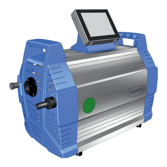
Product description Product description The chemistry diaphragm pumps described essentially consist of a diaphragm pump with VARIO drive, a VACUU·SELECT ® ® vacuum controller, and a VACUU·SELECT Sensor. ® 3.1 Schematic design Side and front view VACUU·SELECT Meaning Sensor, to be mounted externally on suction ®... -
Page 24: Chemistry Diaphragm Pump Series
Product description 3.2 Chemistry diaphragm pump series Overview of chemistry diaphragm pumps Chemistry diaphragm pump Pump heads Stages Mx 1xC VARIO select chemistry ME 16C VARIO select diaphragm pumps MD 12C VARIO select MV 10C VARIO select 20901115_EN_Mx10+12+16C_VARIO_sel_V1.0_130618... -
Page 25: Example
Product description Example Local area vacuum network Example Local area vacuum network Meaning Example: VACUU·LAN , local area vacuum network with three ® valve modules Lab furniture Outlet hose (diverted into a fume hood) Vacuum tubing VACUU·SELECT operating panel + VACUU·SELECT Sensor MD 12C VARIO select diaphragm pump (with accessories: separator at inlet and vapor condenser at outlet) 20901115_EN_Mx10+12+16C_VARIO_sel_V1.0_130618... - Page 26 Product description 20901115_EN_Mx10+12+16C_VARIO_sel_V1.0_130618...
-
Page 27: Installation And Connection
Installation and connection Installation and connection 4.1 Transport Products from VACUUBRAND are packed in sturdy, recyclable packaging. The original packaging is accurately matched to your product for safe transport. If possible, please keep the original packaging, e. g., for >... -
Page 28: Installation
Installation and connection Example Lift out the diaphragm pump (shown with vapor condenser accessory) > Please note that a dia‑ phragm pump can weigh approx. 25 kg. We recom‑ mend using a lifting aid. > Lift the unit out of the pack‑ aging by the side handles. - Page 29 Installation and connection Installing the vacuum pump > Place the vacuum pump on a stable, non‑vibrating, level sur‑ face. Example 5 cm Sketch of minimum distances in lab furniture 5 cm 5 cm > When installing in lab furniture, maintain a minimum distance IMPORTANT! of 5 cm (2 in.) to adjacent objects or surfaces.
-
Page 30: Controller Base
Installation and connection 4.3 Controller base The base, controller, screw fittings and vacuum sensor are en‑ closed separately. Before installation, the base can be mounted on the pump and the controller clipped into place. Alternatively, the controller can be clipped into a recess in the lab furniture or used as a freestanding unit (unfold the stand). -
Page 31: Connection
Installation and connection 4.4 Connection The diaphragm pumps have a vacuum connection and an outlet connection. Connect your diaphragm pump as described in the examples below. 4.4.1 Vacuum connection (IN) CAUTION Flexible vacuum hoses can contract during evacuation. Connected components that are not secured can cause injury or damage due to jerky movement (shrinkage) of the flexible vacuum hose. - Page 32 Installation and connection Connect the vacuum hose Example Vacuum connection at the inlet 1. Take a vacuum hose (a) with a small flange connection KF DN 25. 2. Attach the vacuum hose to pump inlet (b) with a centering ring and clamping ring.
-
Page 33: Outlet Connection (Ex)
Installation and connection 4.4.2 Outlet connection (EX) WARNING Risk of bursting due to overpressure inside the outlet line. Inadmissibly high pressure in the outlet line can cause the vacuum pump to burst or damage seals. The outlet line (exhaust gas, gas outlet) must always >... -
Page 34: Venting Connection (Option)
Installation and connection 4.4.3 Venting connection (option) DANGER Risk of explosion by venting with air. Depending on the application, venting can cause explo‑ sive mixtures to form or other hazardous situations to arise. Never vent processes with air which could form an >... -
Page 35: Gas Ballast (Gb)
Installation and connection 4.4.4 Gas ballast (GB) Use of ambient air as gas ballast Example Position of gas ballast valve If ambient air is to be used as gas ballast, nothing needs to be connected at the diaphragm pump; gas ballast valve (d). ... -
Page 36: Electrical Connection
Installation and connection 4.4.5 Electrical connection Pump electrical connection Example Electrical connection for pump 1. Plug the connector (s) on the power cable into the power con‑ nection of the vacuum pump. 2. Plug power plug (t) into the power outlet. 5 Vacuum pump electrically connected. - Page 37 Installation and connection IMPORTANT! > Use the power plug which fits your power supply. > Do not use multiple sockets connected in series as the power connection. 20901115_EN_Mx10+12+16C_VARIO_sel_V1.0_130618...
- Page 38 Installation and connection 20901115_EN_Mx10+12+16C_VARIO_sel_V1.0_130618...
-
Page 39: Commissioning (Operation)
Commissioning (operation) Commissioning (operation) 5.1 Switch on Switch pump on Switch pump on 1. Switch rocker switch (a) on – switch position I. 2. Press ON/OFF button (b) on the controller. 5 The start screen is displayed. 5 After approx. 30 seconds, the process screen with the operating elements appears on the controller display. - Page 40 Commissioning (operation) Process screen Vacuum controller process screen Status bar Analogue pressure display – pressure curve Digital pressure display – pressure value (target value, actual value, pressure unit) Process screen with context features Screen navigation Operating elements for control Operating elements Button Vacuum controller Function...
-
Page 41: Operation ( See Description Of Controller)
Commissioning (operation) 5.2.1 Operation ( see description of controller) Start the vacuum controller Start Stop the vacuum controller Stop Venting Venting 20901115_EN_Mx10+12+16C_VARIO_sel_V1.0_130618... -
Page 42: Operation With Gas Ballast
Commissioning (operation) 5.2.2 Operation with gas ballast Meaning The provision of gas ballast (= addition of gas) ensures that vapors do not condense inside the vacuum pump but are instead ejected from the pump. This makes it possible to pump larger amounts of condensable vapors, and also prolongs the service life. -
Page 43: Shutdown (Switch Off)
Commissioning (operation) 5.3 Shutdown (switch off) Take the pump out of operation 1. Stop the process and let the diaphragm pump run on for Switch pump off about 30 minutes, with open gas ballast or open inlet. 5 Condensate and media residues will be flushed out of the vacuum pump. -
Page 44: Storage
Commissioning (operation) 5.4 Storage Store the vacuum pump 1. Clean the vacuum pump if dirty. 2. Recommendation: Perform preventive maintenance before storing the vacuum pump. This is especially important if it ran more than 15,000 operating hours. 3. Close the suction and outlet lines, e. g., with the transport caps. -
Page 45: Troubleshooting
VACUU·BUS plug‑in in connection and measured val‑ connection or cables cables to the con‑ defective or not con‑ troller. nected. Specialist Sensor defective. Replace defective components. 1 -> Phone: +49 9342 808-5660, fax: +49 9342 808-5555, service@vacuubrand.com 20901115_EN_Mx10+12+16C_VARIO_sel_V1.0_130618... - Page 46 Troubleshooting Error ` Possible cause Personnel Error – Cause – 3Remedy Remedy Specialist Venting valve No voltage applied. Check VACUU·BUS plug‑ does not oper‑ VACUU·BUS plug‑in in connection and connection or cables cables to the con‑ defective or not con‑ troller.
- Page 47 Troubleshooting Error ` Possible cause Personnel Error – Cause – 3Remedy Remedy Resp. spe- Vacuum line too long Use a shorter vac‑ cialist or cross‑section too uum line with a small. larger cross‑sec‑ tion. Operator Condensate inside Allow vacuum the vacuum pump. pump to run for a few minutes with the suction nozzle...
- Page 48 Troubleshooting Error ` Possible cause 3Remedy Personnel Specialist Loud operating Ball bearing defec‑ Service the vacuum tive. pump and replace noises defective parts or Outlet line open. send in the device. Check outlet line connections. Connect the out‑ let line to an extrac‑ tion system or fume hood.
-
Page 49: Cleaning And Maintenance
Cleaning and maintenance Cleaning and maintenance WARNING Danger due to electrical voltage. Switch the device off before cleaning or maintenance > > work. Unplug the power plug from the socket. > > Risk from contaminated parts. Pumping hazardous media can result in hazardous substances adhering to internal parts of the pump. -
Page 50: Information On Service Work
Cleaning and maintenance 7.1 Information on service work Recommended maintenance intervals Maintenance intervals* If required 15,000 h Replace diaphragms Replace valves Replace O‑rings Clean or replace molded PTFE hose Clean the vacuum pump * Recommended maintenance interval according to operating hours and under normal operating conditions;... - Page 51 Tools needed for maintenance Example Tools Tool Size Service kit Service kit MD 12C / MV 10C VARIO select #20696839 Service kit ME 16C VARIO select #20696867 Diaphragm wrench #20636554 SW66 Flat nose pliers To secure the hose clips Flat‑head screwdriver...
-
Page 52: Cleaning
Cleaning and maintenance 7.2 Cleaning IMPORTANT! This chapter does not contain descriptions for decontamina‑ tion of the product. This chapter describes simple measures for cleaning and care. > Before cleaning, switch off the diaphragm pump. 7.2.1 Diaphragm pump Clean the surfaces Clean dirty surfaces with a clean, slightly damp cloth. -
Page 53: Diaphragm Pump Maintenance
Cleaning and maintenance 7.3 Diaphragm pump maintenance 7.3.1 Maintenance items Items that require maintenance Example Diaphragm pump, front, semi‑transparent view Maintenance items and sequence Meaning Suction/pressure distributor Right pump head pair Bottom pump head pair Left pump head pair Top pump head pair Straightforward maintenance due to split work steps. -
Page 54: Preparation
Cleaning and maintenance 7.3.2 Preparation Disassemble the controller and base see also chapter: 4.3 Controller base on page 30 Disassemble the device and housing sections Disassemble the front housing section 1. Switch the diaphragm pump off 2. Remove the cap from the gas and unplug the power plug. - Page 55 Cleaning and maintenance Disassemble the outlet hose 5. Open the hose clip on the 6. Unscrew the 2 screws from the molded hose leading to the outlet holder; hex key size 3. outlet; flat‑head screwdriver size 1. 5 Diaphragm pump is pre‑ 7.
-
Page 56: Suction/Pressure Distributor Maintenance
Cleaning and maintenance 7.3.3 Suction/pressure distributor maintenance This description only applies to the following diaphragm pumps: MD 12C and MV 10C VARIO select. Exploded drawing of suction/pressure distributor (example) Example Pressure relief valve Pressure relief valve + O‑ring maintenance... - Page 57 Cleaning and maintenance Replace pressure relief valve + O‑ring 1. Place the vacuum pump on 2. Only open the hose clips above a clean, stable surface as the pressure distributor; flat‑ shown. head screwdriver size 1. 3. Remove the molded hoses 4.
- Page 58 Cleaning and maintenance 7. Replace the used O‑ring. 8. Clean the pressure distributor if necessary. Bottom 9. Place the new pressure relief 10. Position the suction distributor valve on the clean surface. with screws and wind in the Ensure the pressure relief screw fittings until hand‑tight;...
-
Page 59: Change The Diaphragms And Valves
Cleaning and maintenance 7.3.4 Change the diaphragms and valves Disassemble the next housing sections 1. Unscrew the 4 screws from the 2. Remove the housing section rear housing section; hex key and set it aside. size 4. 3. Unscrew the screws from the 4. - Page 60 Cleaning and maintenance Remove the side panel 1. Unscrew the 2 outer screws 2. Place the pump carefully on its from the retaining plate; hex side. key size 4. Remove the right side panel 3. Unscrew the screw fittings 4. Lift the side panel off the pump. from the side panel;...
- Page 61 Cleaning and maintenance Exploded drawing of pump head (example) Valve maintenance Clamping claw + screw fittings Disc springs Valve terminals Valves O‑ring size 26 x 2 Diaphragm maintenance Head cover + screw fittings Diaphragm clamping disc with square head screw Diaphragms Diaphragm support disc Spacer discs, max.
- Page 62 Cleaning and maintenance Right pump head pair Example Right pump head pair 1. Open the hose clips on the out‑ 2. Pull off the molded hoses. er hoses. Flat‑head screwdriver size 1. 3. Unscrew the socket head 4. Remove the pump head pair screws from the head covers.
- Page 63 Cleaning and maintenance Replace the diaphragms Example Diaphragm replacement 1. Lift the diaphragm upwards on 2. Carefully position the dia‑ either side. phragm wrench on the dia‑ phragm support disc and unscrew the assembly with the diaphragm wrench attached. 3.
- Page 64 Cleaning and maintenance Example Diaphragm replacement 5. Pull out the diaphragm clamp‑ 6. Place the new diaphragm over ing disc and remove the used the square head of the clamp‑ diaphragm. ing disc. IMPORTANT! > Ensure that the diaphragm is inserted correctly, with the coated, light‑colored side facing upwards.
- Page 65 Cleaning and maintenance Example Diaphragm replacement 9. Hold the spacer discs firmly 10. Initially tighten the assembly and place all the components with the diaphragm wrench carefully on the connecting rod by hand. thread. 11. Then position a torque 12.
- Page 66 Cleaning and maintenance Replace the valves Example Valve replacement 1. Take the pump head pair 2. Unscrew the Torx screws. Torx which you had set aside. screwdriver, size Tx20. 3. Remove the clamping claws 4. Remove the valve terminals from the valve terminals.
- Page 67 Cleaning and maintenance 5. Carefully remove the used 6. Check the surfaces for dirt. O‑rings and valves. 7. Clean dirty surfaces carefully. 8. Insert the new sealing rings into the grooves. 9. Place the new valves on top Cutout view from above: correct and align them.
- Page 68 Cleaning and maintenance 10. Place both valve terminals 11. Place the clamping claws with the disc springs on the on the valve terminals and pump heads. tighten the screw fittings first by hand, then with a torque wrench to 3 Nm. 12.
- Page 69 Cleaning and maintenance Bottom pump head pair Service the bottom pump head pair > Follow the same procedure to change the diaphragms and valves as for the Right pump head pair, on pages 62 to 68 Left and top pump head pair Service the left and top pump head pair 1.
- Page 70 Cleaning and maintenance Remove the left side panel 3. Unscrew the screw fittings 4. Lift the side panel off the pump. from the side panel; hex key size 5. Left pump head pair Top pump head pair 5. Follow the same procedure to change the diaphragms and valves as for the Right pump head pair, on pages 62 to 68...
- Page 71 Cleaning and maintenance Assemble the device and housing sections Before restarting the pump, all parts of the device and housing which had been removed must be fixed back in place. Mount the side panel 1. Replace the side panel on the 2.
- Page 72 Cleaning and maintenance 7. Wind in the 2 outer screws of 8. Secure the cable in the rear the retaining plate; hex key recess. size 4. Assemble the rear housing section 9. Wind in the screws of the side 10. Replace the rear housing panel retaining plate;...
- Page 73 Cleaning and maintenance Assemble the outlet holder 13. Wind in the 2 screws of the 14. Secure the hose clip, e. g., outlet holder; hex key size 3. with flat nose pliers. Assemble the front housing section 15. Replace the front housing 16.
- Page 74 Cleaning and maintenance 18. Secure the controller on the 19. Plug in the power plug. diaphragm pump and connect all cables. If maintenance work has been completed in full: > Connect the hoses for operation. > Connect the diaphragm pump to the power supply. 5 Diaphragm pump is ready to be returned to use.
-
Page 75: Appendix
Appendix Appendix 8.1 Technical information Chemistry diaphragm pump series ME 16C VARIO select MD 12C VARIO select MV 10C VARIO select 8.1.1 Technical data Technical data Ambient conditions (US) Ambient temperature, max. 10–40 °C 50‑104 °F Working temperature 10‑40 °C 50‑104 °F... - Page 76 Ultimate vacuum, abs. 1.5 mbar 1.1 Torr Ultimate vacuum with GB, 3 mbar 2.2 Torr abs. Number of cylinders/stages MV 10C VARIO select Max. pump rate 13 m 7.7 cfm Ultimate vacuum, abs. 0.6 mbar 0.45 Torr Ultimate vacuum with GB, 1.2 mbar...
- Page 77 533 mm x 260 mm 21.0 in x 10.2 in x 17.7 in x 450 mm Weight* 25.5 kg 56.2 lb MV 10C VARIO select 533 mm x 260 mm 21.0 in x 10.2 in x 17.7 in x 450 mm Weight* 25.5 kg 56.2 lb...
-
Page 78: Wetted Materials
ETFE carbon fiber reinforced Diaphragm clamping disc ETFE carbon fiber reinforced Diaphragms PTFE Valves MD 12C VARIO select / FFKM MV 10C VARIO select Valves ME 16C VARIO select PTFE O‑rings Valve terminals ECTFE, carbon fiber reinforced Hose fittings ETFE/ECTFE... -
Page 79: Rating Plate
Appendix 8.1.3 Rating plate Data on rating plate In the event of an error, make a note of the type and serial > > number on the rating plate. When contacting our Service Department, please provide > > the type and serial number from the rating plate. This will allow us to provide you with specific support and advice for your device. -
Page 80: Ordering Information
Order no. for pump series ME 16C VARIO select 207417xx MD 12C VARIO select 207437xx MV 10C VARIO select 207447xx * Order no. depends on power cable CEE, CH, UK, US, CN, IN Accessories Ordering information Order no. for accessories... - Page 81 Chemistry diaphragm pumps. Sources of supply Purchase original accessories and original spare parts from a International subsidiary of VACUUBRAND GMBH + CO KG or your local dis‑ sales offices and distribution tributor. Information about our complete product range is available >...
-
Page 82: Service
Calibration (DAkkS‑accredited) ƒ With Health and Safety Clearance form: return, disposal. ƒ > Visit our website for further information: www.vacuubrand.com. Service handling 1. Contact your local distributor or our Service Department. Meet the terms of service 2. Request an RMA no. for your order. -
Page 83: Index
Appendix 8.4 Index Index Abbreviations ....9 Labels and signs ....20 Accessories . - Page 84 Appendix Index Residual energy ....18 Responsibility matrix ... . 14 Return (reshipment) ... . . 82 Return to use after maintenance .
-
Page 85: Eu Declaration Of Conformity
EC Declaration of Conformity Déclaration CE de conformité Hersteller / Manufacturer / Fabricant: VACUUBRAND GMBH + CO KG · Alfred‑Zippe‑Str. 4 · 97877 Wertheim · Germany Hiermit erklärt der Hersteller, dass das Gerät konform ist mit den Bestimmungen der Richtlinien:... -
Page 86: En_Mx10+12+16C_Vario_Sel_V1.0
20901115_EN_Mx10+12+16C_VARIO_sel_V1.0_130618... - Page 87 20901115_EN_Mx10+12+16C_VARIO_sel_V1.0_130618...
- Page 88 Technology for Vacuum Systems Manufacturer: VACUUBRAND GMBH + CO KG Alfred‑Zippe‑Str. 4 97877 Wertheim GERMANY Phone: ƒ Head office +49 9342 808‑0 ƒ Sales +49 9342 808‑5550 ƒ Service +49 9342 808‑5660 Fax: +49 9342 808‑5555 Email: info@vacuubrand.com Web: www.vacuubrand.com...
Need help?
Do you have a question about the MV 10C VARIO select and is the answer not in the manual?
Questions and answers