Table of Contents
Advertisement
Tower Hobbies
guarantees this kit to be free from defects in both material and workmanship at the date of purchase. This
®
warranty does not cover any component parts damaged by use or modification. In no case shall Tower Hobbies' liability
exceed the original cost of the purchased kit. Further, Tower Hobbies reserves the right to change or modify this warranty
without notice.
In that Tower Hobbies has no control over the final assembly or material used for final assembly, no liability shall be assumed
nor accepted for any damage resulting from the use by the user of the final user-assembled product. By the act of using the
user-assembled product, the user accepts all resulting liability.
If the buyer is not prepared to accept the liability associated with the use of this product, the buyer is advised to return this
kit immediately in new and unused condition to the place of purchase.
READ THROUGH THIS MANUAL COMPLETELY BEFORE STARTING CONSTRUCTION. IT CONTAINS IMPORTANT
INSTRUCTIONS AND WARNINGS CONCERNING THE ASSEMBLY AND USE OF THIS MODEL.
®
© Copyright 2003 V 1.0
WARRANTY
®
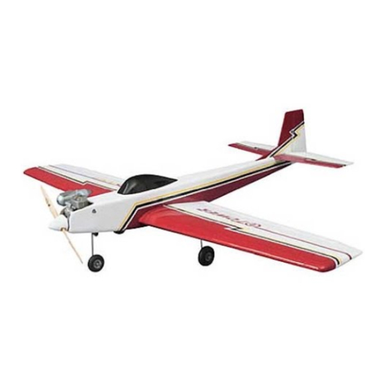
Wingspan: 55.5 in [1,415mm]
Wing Area: 585 sq in [38dm
Weight: 5 - 6 lbs [2,270 - 2,720g]
Length: 48.5 in [1,232mm]
Wing Loading: 19.5 - 24 oz/sq ft [59 - 73g/dm
Engine: .40 - .46 cu in [6.5 - 7.5cc] two-stroke
.48 - .70 cu in [8.0 - 11.5cc] four-stroke
Radio: 4-channel, four servos
Tower Hobbies
P.O. Box 9078
Champaign, IL 61826
(800) 637-6050
www.towerhobbies.com
TOWZ1150 for TOWA2052
]
2
]
2
Advertisement
Table of Contents

Related Manuals for Tower Hobbies Tower Kaos 40 MKII


Summary of Contents for Tower Hobbies Tower Kaos 40 MKII
- Page 1 In that Tower Hobbies has no control over the final assembly or material used for final assembly, no liability shall be assumed nor accepted for any damage resulting from the use by the user of the final user-assembled product. By the act of using the user-assembled product, the user accepts all resulting liability.
-
Page 2: Table Of Contents
PROTECT YOUR MODEL, YOURSELF & TABLE OF CONTENTS OTHERS...FOLLOW THESE IMPORTANT SAFETY PRECAUTIONS INTRODUCTION .............2 SAFETY PRECAUTIONS ............2 ADDITIONAL ITEMS REQUIRED ........3 1. Your Tower Kaos .40 ARF should not be considered a toy, Hardware & Accessories..........3 but rather a sophisticated, working model that functions very Optional Supplies &... -
Page 3: Additional Items Required
In addition to common household tools and hobby tools, this KIT INSPECTION is the “short list” of the most important items required to build the Tower Hobbies Kaos .40. Tower Hobbies Build-it ™ CA and Epoxy glue are recommended. Before starting to build, take an inventory of this kit to make sure it is complete, and inspect the parts to make sure they HARDWARE &... -
Page 4: Parts List
PARTS LIST Fuselage Wing Bolt Block Left Wing Panel w/Aileron 10 Aileron Servo Tray (3 pcs.) Right Wing Panel W/Aileron 11 Spinner Fin/Rudder 12 Nose Landing Gear Engine Mount 13 Main landing Gear Fuel Tank 14 Canopy Wing Joiners (2 pcs.) 15 Stabilizer/Elevator Wheels 2-1/2"... -
Page 5: Preparations
PREPARATIONS 1. If you have not done so already, remove the major parts of the kit from the box and inspect for damage. If any parts are damaged or missing, contact Order Assistance at the telephone number listed in the “Kit Inspection” section on page 3. -
Page 6: Join The Wings
JOIN THE WINGS 4. Using a felt-tip pen, mark a box 1-3/4" x 2-3/8" [44 x 60mm]. 1. Locate the two plywood wing joiners. Using 6-minute epoxy, glue the joiners together. 5. Cut through the sheeting on the lines you have drawn with a hobby knife. - Page 7 8. Locate the two holes under the covering at the trailing 10. Glue the plywood wing bolt plate onto the bottom of edge of the wing. Cut the covering away on both the top and the wing over the area where you removed the covering. When the bottom of the wing.
-
Page 8: Install The Main Landing Gear
13. Place the belly pan in position on the wing, aligning it with the fuselage. Trace the outline of the belly pan onto the wing with a felt-tip marker. 15. Glue the belly pan in place on the wing, making sure it is aligned with the fuselage. -
Page 9: Install The Aileron Servo
the nylon landing gear straps with two sheet metal screws. allow the glue to cure. Permanently install the servo using the Follow this procedure for the remaining landing gear wire. screws provided with the servos. 2. Locate two nylon aileron torque rod links. Thread them onto the aileron torque rods approximately 20 full turns. -
Page 10: Assemble The Fuselage
in place with a couple of T-pins. Measure from the wing tip to ASSEMBLE THE FUSELAGE the stab, adjusting the stab until the distance is equal. Once the stab is positioned properly use a felt-tip marker to mark the outline of the fuselage on the bottom of the stab. MOUNT THE STAB &... - Page 11 10. Look closely at the trailing edge of the rudder. You will find three pre-cut hinge slots. Look at the fin and you will see that there are two pre-cut hinge slots in the fin. Position the rudder against the fin, aligning the hinge slots. The lower hinge on the rudder does not have a matching slot on the bottom of the fuselage.
-
Page 12: Install The Nose Gear
INSTALL THE NOSE GEAR 1. Locate the aluminum engine mount. Turn the mount over and take notice of the recesses on the bottom of both rails. Locate four 4mm nuts. Test fit the nuts into the recesses in the bottom of the landing gear rails. Once the nuts are properly seated in the rails, carefully apply a small drop of medium CA glue onto the edge of the nuts. - Page 13 steering arm and into the bottom of the engine mount. Apply a drop of threadlocker to the set screw. Then, tighten the set screw in the steering arm onto the flat spot on the landing gear wire. 7. The nylon steering arm has three holes. Cut the end hole from the steering arm.
-
Page 14: Install The Fuel Tank & Engine
INSTALL THE FUEL TANK & ENGINE engine compartment. Make the necessary adjustments as needed to allow your engine to fit. 1. Locate the fuel tank. Remove the parts from inside of the tank. 6. Locate the plastic spinner. Remove the nut and washer from the engine crankshaft and slide the spinner onto the crankshaft. -
Page 15: Install The Radio & Servos
INSTALL THE RADIO & SERVOS 9. Locate the .074 x 16" [406mm] pushrod, threaded on one end. Thread a nylon clevis onto the threaded portion of the rod approximately 20 full turns. Install a silicone clevis keeper onto the bottom of the clevis. 10. - Page 16 the silicone clevis keeper over the clevis. Repeat this for all three pushrods. 5. Locate the three components of the screw-lock connector: the 3 x 5mm set screw, connector and the knurled nut. Remove the servo arm from your throttle servo. Drill the outermost hole of the servo arm with a 5/64"...
- Page 17 7. Cut a notch in the former behind the fuel tank for the 10. Insert the throttle pushrod into the screw-lock connector. nose gear steering pushrod tube. Sand the tube with 220-grit Center the servo and then tighten the set screw against the sandpaper where the tube rests in the notch you made.
- Page 18 13. Locate two 4mm wheel collars and two 3 x 5mm set 16. Locate one of the discarded servo arms you cut off screws. Slide them over both of the elevator pushrods. Center earlier. You are going to use it as a strain relief for your receiver both halves of the elevator.
-
Page 19: Get The Model Ready To Fly
SET THE CONTROL THROWS 19. Be sure all servo lines are plugged into the receiver. Permanently secure the receiver and battery into the fuselage holding them in place by gluing a couple of balsa sticks (not Use a Great Planes AccuThrow (or a ruler) to accurately supplied) into the fuselage. -
Page 20: Balance The Model Laterally
At this stage the model should be in ready-to-fly condition 4. IMPORTANT: If you found it necessary to add any with all of the systems in place including the engine, landing weight, recheck the C.G. after the weight has been installed. gear, covering, and the radio system. -
Page 21: Balance The Propellers
BALANCE THE PROPELLERS ENGINE SAFETY PRECAUTIONS Failure to follow these safety precautions may result in severe injury to yourself and others. Keep all engine fuel in a safe place, away from high heat, sparks or flames, as fuel is very flammable. Do not smoke near the engine or fuel;... -
Page 22: Check List
proven to be airworthy by having been previously Extend your receiver antenna and make sure it has a successfully flight tested. strain relief inside the fuselage to keep tension off the solder joint inside the receiver. 2. I will not fly my model aircraft higher than approximately Balance your model laterally as explained in the 400 feet within 3 miles of an airport without notifying the instructions. -
Page 23: Takeoff
level, but use this first flight to become familiar with your CAUTION (THIS APPLIES TO ALL R/C AIRPLANES): If, model before landing. while flying, you notice any unusual sounds, such as a low-pitched “buzz,” this may indicate control surface LANDING flutter. - Page 24 BUILDING NOTES Kit Purchased Date: ___________________________ Date Construction Finished: ____________________ Where Purchased: ____________________________ Finished Weight:______________________________ Date Construction Started: _____________________ Date of First Flight:____________________________ FLIGHT LOG...
Need help?
Do you have a question about the Tower Kaos 40 MKII and is the answer not in the manual?
Questions and answers