Table of Contents
Advertisement
Quick Links
®
T T O O W W E E R R T T R R A A I I N N E E R R 4 4 0 0
RADIO CONTROLLED MODEL AIRPLANE KIT
INSTRUCTION MANUAL
TTR4P03 V 1.0
READ THROUGH THIS INSTRUCTION BOOK BEFORE BEGINNING
CONSTRUCTION. THIS BOOKLET CONTAINS WARNINGS AND
PRECAUTIONS REGARDING THE USE OF THIS PRODUCT.
WARRANTY
Tower Hobbies guarantees this kit to be free from defects in
both materials and workmanship at the date of purchase. This
warranty does not cover any component parts damaged by use
or modification. In no case shall Tower's liability exceed the
original cost of the purchased kit. Further, Tower reserves the
right to change or modify this warranty without notice.
In that Tower has no control over the final assembly or material
used for final assembly, no liability shall be assumed nor
accepted for any damage resulting from the use by the user of
the final user-assembled product. By the act of using the user-
assembled product, the user accepts all resulting liability.
If the buyers are not prepared to accept the liability
associated with the use of this product, they are advised to
return this kit immediately in new and unused condition to
Tower Hobbies.
™
O
-
UR ALL
TIME FAVORITE TRAINER
N
OW IN KIT FORM
DIE PATTERNS ...............................................................4&5
ITEMS REQUIRED FOR COMPLETION ..............................6
GET READY TO BUILD .......................................................8
BUILD THE TAIL SURFACES .............................................10
BUILD THE FUSELAGE .....................................................13
BUILD THE WING ............................................................20
FINAL ASSEMBLY..............................................................32
FINISHING .......................................................................40
FINAL CONTROL HOOKUPS...........................................46
PREFLIGHT .......................................................................52
FLYING .............................................................................54
Your Trainer 40 is not a toy, but rather a sophisticated, working
model that functions very much like an actual airplane. Because
of its realistic performance, the Trainer 40, if not assembled and
operated correctly, could possibly cause injury to yourself or
spectators and damage property.
To make your R/C modeling experience totally enjoyable, we
recommend that you get experienced, knowledgeable help with
assembly and during your first flights. You'll learn faster and
avoid risking your model before you're truly ready to solo. Your
local hobby shop has information about flying clubs in your area
whose membership includes qualified instructors.
2
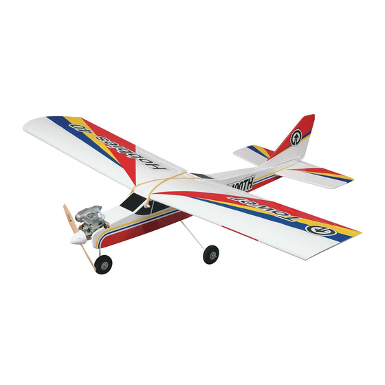
Wing Area: 618 sq. in.
Length: 44.5 in. Wing Loading: 18 to 21 oz./sq. ft.
...
TABLE OF CONTENTS
FOLLOW THIS IMPORTANT SAFETY PRECAUTION TO
PROTECT YOUR MODEL, YOURSELF & OTHERS.
®
Wing Span: 55 in.
Weight: 5 to 5.5 lb.
Engine: .40 2-stroke
Entire Contents © Copyright 1998
Advertisement
Table of Contents

Related Manuals for Tower Hobbies Trainer 40


Summary of Contents for Tower Hobbies Trainer 40
-
Page 1: Table Of Contents
Further, Tower reserves the right to change or modify this warranty without notice. Your Trainer 40 is not a toy, but rather a sophisticated, working In that Tower has no control over the final assembly or material model that functions very much like an actual airplane. -
Page 2: Die Patterns
The Tower Trainer 40 is designed to fly as well as it looks. Its structurally sound. Be sure to check external nylon clevises thick, flat-bottom wing offers strong lift at slow speeds and great often. -
Page 3: Items Required For Completion
Screw-Lock connectors (Great Planes #GPMQ3870) and pushrod exit. Note: The displacement in bold type is the most highly recommended. However, all of these engines will fly the Tower Trainer 40. SUGGESTED SUPPLIES AND TOOLS Selection of wheels We recommend Great Planes Pro ™... -
Page 4: Get Ready To Build
30-Minute Epoxy (Tower Hobbies #TOWR3350) Common abbreviations used in this book and on the plan ProWood glue (Great Planes #GPMR6160, optional) Elev. = Elevator Hand or Electric Drill Fuse = Fuselage Drill Bits: 1/16", 5/64", 3/32", 1/8", 5/32", 3/16", 1/4"... -
Page 5: Build The Tail Surfaces
Epoxy is available in many different formulas having different cure times. The single best type of epoxy to have when building your Tower Trainer 40 is one 1. Cut the "Stabilizer/Elevator" section from the fuselage plan which sets up in 30 minutes, but you may also find 6-minute sheet and tape it on your building board. - Page 6 BUILD THE FIN AND RUDDER 1. Cut the "Fin/Rudder" section from the fuselage plan sheet and tape it on your building board. Tape a piece of wax paper or Plan Protector over the plan. Build the frame of the Fin using a 1/4"...
-
Page 7: Build The Fuselage
CAUTION!!!: You must use extreme care when cutting hinge slots with a hobby knife, to avoid cutting yourself! If the balsa C. Trial fit the hinge into the slot. If the hinge is difficult to part breaks while you are pushing on the knife, the blade could push in, re-insert the knife and move it back and forth in go into your hand before you know it! A good precaution is to the slot a few times to enlarge the slot. - Page 8 8. Using a 1/4" x 1/4" x 36" balsa stick, make the Center 12. Make the Fuse Rails for the Left Fuse Side using the same Stringer. Use medium CA to glue it into position. Using leftovers technique from the right side. The Left Fuse Side must match the saved from the assembly of the Fin and Stab, cut the center Right as closely as possible, or the fuselage will not be straight supports and glue them into position.
- Page 9 5. Test fit 1/8" plywood Former F2 in place on the Right Fuse 8. Test fit the die-cut 1/8" plywood Landing Gear Plate (LGP). Side. Press it down into its slot and use a 90 degree triangle to Once satisfied with the fit, glue it with 6-minute epoxy. keep it perpendicular to the fuse side.
-
Page 10: Build The Wing
BUILD THE WING Note: The Tower Trainer 40 wing, much like the fuselage, is designed with simplicity and ease of building in mind. Always 20. Measure the distance from each tip of the Main Landing remember to test fit parts before using glue to make any Gear to the tail of the fuse. - Page 11 1. Cut the “Right Wing Panel” section from the wing plan sheet Either break the pieces apart and clean up the rough edges with a and tape it on your building board. Tape a piece of wax paper or sanding block or carefully run a knife down the edge between the Plan Protector over the plan.
- Page 12 15. With the panel held flat on the table, use Medium CA to glue the balsa Shear Webs to the Spars, between the R-3 ribs. Note: The function of the shear webs is to keep the spars from collapsing. They will not touch or be glued to the ribs. They should be thoroughly glued to the spars.
-
Page 13: Join The Wing
sanding items such as the wing tips to protect areas you don’t 2. Test fit the two wing panels together with the dihedral braces want sanded. in place. Check to see the spars, leading edges and trailing edges match up well. Make adjustments if necessary. Repeat steps 5-25 over the Left Wing Panel plan to build the Left Wing. - Page 14 8. Use Medium CA to glue Wing Rib R-1C in place. It is centered to allow for the top and bottom center section sheeting as shown in the cross-section drawing beside the right wing panel. 6. The plywood die-cut 1/8" Aft Center Brace (A) is centered on the trailing edges.
- Page 15 WRONG RIGHT 14. Hold the trailing edge center pieces up to the wing. Transfer the notch locations onto the wing. Use a knife to cut small notches into the wing TE. 17. Use medium CA to glue the trailing edge center assemblies 15.
-
Page 16: Final Assembly
4. Cut a couple of leftover 1/16" sheets and glue them inside of the wing as shown, to support and strengthen the sheeting around the servo cut out. 2. Sheet the bottom of the other wing panel in the same manner. 3. - Page 17 MOUNT THE HORIZONTAL STABILIZER T-PIN STRING STRING Wing/Stab Align 1. Attach the wing to the fuse (for reference) and slide the Stabilizer into its slot. Center the Stabilizer left and right in the slot. Hold a string (with one end attached to a pin centered at F-1) out to a wing tip.
- Page 18 3. Test fit the Dorsal Fin into position in front of the Fin as shown. The Dorsal Fin should fit flush against both the Fuselage Top and Fin. Sand as necessary to provide for a good fit of the Dorsal Fin. Use a straightedge to make sure the Dorsal Fin is aligned with the Fin.
- Page 19 10. From another piece of outer pushrod tube, cut the nose INSTALL THE NOSE GEAR steering guide tube. It should be flush with the front of the firewall and extend 1/2" aft of F-2. Temporarily install the nose 1. Remove the engine from the engine mount. Slide a 5/32" steering guide tube in the firewall and F-2.
-
Page 20: Finishing
FLAT SPOT 5. Slide the wire through the guide tube and place the arm on the nose gear sticking out of the engine mount. Position the steering arm as shown on the plan, then temporarily tighten the NOTE: Do not file the "flat spot" until step #3 on page 51. set screw. - Page 21 Modelers who have not used iron-on coverings should refrain from attempting complicated trim schemes. You may add stripes, graphics and various designs to your Tower Trainer 40. These are cut from different colors of covering, then ironed directly over the base color. If you are new to iron-on coverings...
- Page 22 Wing C. Cover the stab and fin with the pieces you cut earlier. 1. Ends of ailerons 2. Bottoms, then tops of ailerons D. Perform the same operation for the other side of the stab 3. TE of wing (the hinge line) and fin.
-
Page 23: Final Control Hookups
the hinges to keep them centered. Close the hinge gap to 1/32" Do not use accelerator on any of the hinges. Do not glue the or less – it is better to have a slight gap to avoid inadvertently hinges with anything but thin CA and do not attempt to glue gluing the control surfaces together. - Page 24 The balance point (CG) is shown on the plan. On 16. Install the switch harness in the location you desire. It is the Tower Trainer 40 the (CG) is located 3-5/8" back from the always best the switch be on the opposite side of the muffler to leading edge.
- Page 25 landing. Moving the balance aft makes the model more agile 6. Confirm that the battery is securely wrapped in foam and is with a lighter and snappier feel. Please start at the location we packed in tight enough under the tank floor so that it cannot shift recommend and do not at any time balance your model outside during flight or a rough landing.
-
Page 26: Preflight
Tighten the steering arm screw directly over the flat. It is a good practice to periodically check the ground stance of your Tower Trainer 40 – especially after a hard landing. The wire landing gear is designed to absorb shock from rough landings but occasionally may need to be bent back into position. -
Page 27: Flying
The moment of truth has finally arrived. You've put a lot of effort into building your Tower Trainer 40 and it looks great! Protect 3. Where established, I will abide by the safety rules for the flying... - Page 28 Tower Trainer 40 lifts off. Try this zip-top storage bag partially filled with talcum powder or several times, adding a little more power each time.
- Page 29 The Tower Trainer 40 has a lot of lift so you will need a slow, reliable idle in order to achieve a nice, slow landing. Allow the plane to keep descending on a gradual glide slope until you are about 3 feet off the runway.
-
Page 30: Tower Hobbies
(TOWR3200) (TOWR3250) A wide nozzle on Tower’s Deluxe Heat Gun ensures uniform, Tower Hobbies’ thermostat-controlled Custom Sealing Iron tacks drum-tight "shrink" over wide areas—and it can't scratch because covering tight anywhere. It features a tapered, upswept, non-stick it never touches the covering's surface. Includes heavy-duty motor sole for easy use in the tightest corners;...
Need help?
Do you have a question about the Trainer 40 and is the answer not in the manual?
Questions and answers