Table of Contents
Advertisement
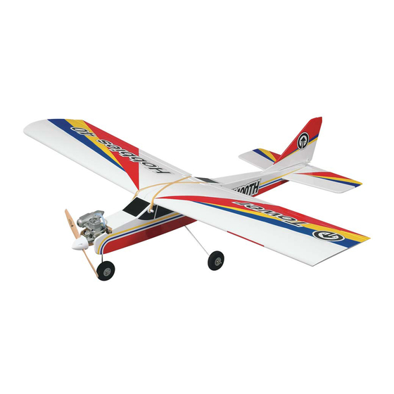
TOWER TRAINER
ALMOST-READY-TO-FLY RADIO CONTROLLED MODEL AIRPLANE
Tower Hobbies
®
guarantees this kit to be free from defects in both material and workmanship at the date of purchase.
This warranty does not cover any component parts damaged by use or modification. In no case shall Tower Hobbies'
liability exceed the original cost of the purchased kit. Further, Tower Hobbies reserves the right to change or modify
this warranty without notice.
In that Tower Hobbies has no control over the final assembly or material used for final assembly, no liability shall be
assumed nor accepted for any damage resulting from the use by the user of the final user-assembled product. By the act
of using the user-assembled product, the user accepts all resulting liability.
If the buyer is not prepared to accept the liability associated with the use of this product, the buyer is advised to
return this kit immediately in new and unused condition to the place of purchase.
READ THROUGH THIS MANUAL COMPLETELY BEFORE STARTING CONSTRUCTION. IT CONTAINS
IMPORTANT INSTRUCTIONS AND WARNINGS CONCERNING THE ASSEMBLY AND USE OF THIS MODEL.
®
© Copyright 2002 V 1.0
ASSEMBLY INSTRUCTIONS
WARRANTY
®
60 MKII
™
Wingspan: 69 in [1,753mm]
Wing Area: 880 sq in [57 dm
Weight: 7.25 lbs [3,289 g] Length: 56.5 in [1,435mm]
Wing Loading: 19 oz/sq ft [58 g/dm
Engine: .61 cu in [10 cc] two-stroke
Radio: 4 channel
Tower Hobbies
P.O. Box 9078
Champaign, IL 61826
(800) 637-6050
www.towerhobbies.com
2
]
2
]
TOWZ1153 for TOWA1010
Advertisement
Table of Contents

Related Manuals for Tower Hobbies TOWER TRAINER 60 MKII


Summary of Contents for Tower Hobbies TOWER TRAINER 60 MKII
-
Page 1: Right Wing Panel
In that Tower Hobbies has no control over the final assembly or material used for final assembly, no liability shall be assumed nor accepted for any damage resulting from the use by the user of the final user-assembled product. By the act of using the user-assembled product, the user accepts all resulting liability. -
Page 2: Table Of Contents
INTRODUCTION ..............2 SAFETY PRECAUTIONS SAFETY PRECAUTIONS ..........2 ADDITIONAL ITEMS REQUIRED ........3 1. Your Tower Trainer 60 MKII ARF should not be ENGINE RECOMMENDATIONS........3 considered a toy, but rather a sophisticated, working model RADIO RECOMMENDATIONS ........3 that functions very much like a full-size airplane. Because of COVERING ACCESSORIES........3... -
Page 3: Additional Items Required
Academy of Model Aeronautics 5151 East Memorial Drive Here is a list of optional tools mentioned in the manual that Muncie, IN 47302-9252 will help you assemble the Tower Trainer 60 MKII ARF. Tele. (800) 435-9262 Great Planes CG Machine ™... -
Page 4: Assemble The Wing
ASSEMBLE THE WING JOIN THE WING 1. In order to assemble the wing you will need the following items as shown in the photo above. Right Wing Panel (1) Left Wing Panel (1) Right Aileron (1) Left Aileron (1) CA Hinges (8) Wing Joiners (4) Aileron Servo Tray (1) Aileron Servo Tray Mounting Blocks (2) - Page 5 4.Test fit the aileron servo in the 3mm plywood aileron servo tray. If necessary, trim the opening in the tray to accommodate the servo. Once you are satisfied with the fit of the servo, remove it from the tray and set it aside for now. 7.
-
Page 6: Hook Up The Ailerons
10. Test fit the wing joiner into one wing panel, then the other. Be certain the joiner is installed upright with the joiner angled upward for wing dihedral. Also make sure that the joiner slides in all the way to the centerline. Test fit the wing 12. - Page 7 1. Take a close look at the supplied hinges. The above 4. Coat the “arm” portion of the aileron torque rod that photo has this slot highlighted and must be inserted into slips inside the aileron and the groove, and the hole in the place in the proper direction as indicated in the photo.
- Page 8 How to cut covering from balsa. To avoid cutting into the balsa, use a soldering iron instead of a hobby knife to cut the covering from the stab. The tip of the soldering iron doesn't have to be sharp, but a fine tip does work best.
- Page 9 14. After bending the pushrods at your mark, slide the Faslink over the wire and snap it into place on the pushrod. 11. Make a two-arm servo arm by cutting two arms off a four-arm servo arm. Enlarge the outer holes in the arm with a Hobbico Servo Horn Drill (or a #48 or 5/64"...
-
Page 10: Assemble The Fuselage
ASSEMBLE THE FUSELAGE MOUNT THE STABILIZER & FIN 1. In order to complete this section you will need the following items as shown in the photograph above. You will also need the wing (not shown) for alignment purposes. #1 Fuselage (1) #2 Stabilizer (1) #3 Elevator (1) #4 Fin (1) - Page 11 a piece of non-elastic string (K & S #801 Kevlar thread; K&SR4575). Slip the loop in the string over the T-pin. 4. Taking accurate measurements, locate the center of the stab along the trailing edge. Slide the stab into the fuselage and center it over the aft end of the fuselage.
- Page 12 Pen (TOPQ2510) to mark the outline of the fuselage onto location of the fin on top of the fuselage. Using the same the top and bottom of the stab. method as with the stab, cut the covering material from the mark on the bottom of the fin and the top of the fuselage.
-
Page 13: Install The Wing Mounting Dowels
INSTALL THE WING MOUNTING DOWELS 1. For this step you will need the following items as shown in the photograph above. #1 Fuselage (1) #2 Wing Mounting Dowels (2) #3 2.6mm x 8mm Wood Screws (4) #4 Molded Wing Dowel Covers (4) 3. -
Page 14: Install The Fuel Tank
INSTALL THE FUEL TANK Remember (or use a felt-tip pen to mark) which tube is the 1. To complete this step you will need the following items fuel pick-up tube and which tube is the vent (that will be as shown in the photograph above. connected to the pressure fitting on the muffler). -
Page 15: Mount The Engine
MOUNT THE ENGINE NOTE: The engine in your airplane is mounted slightly different from that of most R/C aircraft. This is done to allow the use of many different types of engines. It also allows a “no-drill” approach to ease the engine installation. Read through the procedure and understand all the steps before actually performing them. - Page 16 4. With the engine in place, install the remaining two 4mm x 25mm machine screws, 4mm lock washers, and 4mm nuts in place at the front of the engine mount as shown in the photograph. Do not tighten the screws at this time to allow for the positioning of the engine.
-
Page 17: Mount The Landing Gear
MOUNT THE LANDING GEAR 1. The photo above shows the items you will need to complete this step. These parts are: #1 Fuselage (1) #2 Main Landing Gear (2) #3 Nose Gear (1) #4 Wheels (3), (2 with 5mm axle holes, 1 with 4mm axle holes) #5 4mm x 12mm Phillips Head Screws (2) #6 Nose Gear Bearing Block (1) - Page 18 3mm x 10mm Phillips head wood screws and the nylon and then gently tighten the nut. It is important not to overtighten landing gear straps as shown in the photograph. this nut; this would not allow the screw-lock pushrod connector to rotate on the steering arm while in operation.
-
Page 19: Final Assembly
FINAL ASSEMBLY HOOK UP THE CONTROLS #6 Control Horn Backplates (2) #7 Control Horns (2) #8 2mm x 14mm Phillips Head Screws (4) 1. The items shown in the above photograph will be #9 680mm Threaded Elevator/Rudder Pushrods (2) needed from the airplane kit to complete this step. These #10 Battery/Receiver Tray (1) items are: #11 2.6mm x 8mm Screws (4) - Page 20 3. There is a 5mm hole in the firewall for the pushrod guide tube that will align with the throttle arm on most two-stroke engines. Use medium sandpaper to roughen both plastic pushrod guide tubes. Insert one pushrod guide tube through the hole in the firewall for the throttle, and the other for the steering pushrod guide tube.
-
Page 21: Install The Radio Gear
control horns on the elevator and rudder. At these locations them, creating threads in the wood at all the locations. Add drill 5/64" [2mm] holes through the elevator and rudder for a drop of thin CA to each hole and allow it to harden (it is mounting the control horns with 2mm x 14mm Phillips head best to take the servos out of the tray while doing this to screws. - Page 22 the holes in the servo arms from the bottom of the arms. the throttle servo arm still centered on the servo, tighten the Place nylon Faslinks to each pushrod, and then cut the screw on top of the screw-lock pushrod connector. Using wires with 1/16"...
-
Page 23: Apply The Decals
12. Make a guide tube support by using the supplied 10mm x 13mm x 87mm balsa material. Place it into the fuse 10. Connect the aileron extension, servo leads, battery as shown in the photograph above and mark the locations and switch wires to the receiver as directed by your radio of the throttle and steering guide tubes. -
Page 24: Set The Control Throws
If it doesn’t open far enough or opens too far (bending the rod) move the pushrod and screw- IMPORTANT: The Tower Trainer 60 MKII ARF has been lock pushrod connector in or out on the servo arm and/or the extensively flown and tested to arrive at the throws at which clevis on the carburetor arm to gain or reduce movement. -
Page 25: Balance The Model (C.g.)
Balance the Model (C.G.) model on a Great Planes CG Machine, or lift it at the balance point you marked. More than any other factor, the C.G. (center of gravity or, 3. If the tail drops, the model is “tail heavy” and the battery balance point) can have the greatest effect on how a model pack and/or receiver must be shifted forward or weight must be flies, and may determine whether or not your first flight will... -
Page 26: Balance The Propellers
charge your transmitter and receiver batteries the night before running at various speeds with an assistant holding the model, you go flying, and at other times as recommended by the radio using hand signals to show you what is happening. If the control manufacturer. -
Page 27: Ama Safety Code (Excerpts)
AMA SAFETY CODE (excerpts) Extend your receiver antenna and make sure it has a strain relief inside the fuselage to keep tension off the solder joint inside the receiver. Read and abide by the following Academy of Model Balance your model laterally as explained in the Aeronautics Official Safety Code: instructions. -
Page 28: Using Rubber Bands
flipping the prop, fuel and a means of filling the tank, a couple right turn. The plane does move off to your left from your of small screwdrivers, #64 rubber bands, spare prop and glow vantage point, but if you imagined yourself in the cockpit you plug, 6"... -
Page 29: Landing
the wings, then release the stick. There is a memory aid that CAUTION (THIS APPLIES TO ALL R/C AIRPLANES): If, may help keep you out of trouble when the plane is flying toward while flying, you notice any unusual sounds, such as a low- you –... - Page 30 airplanes and other materials. Note: Most CA glues will the airplane about the pitch axis and causes the airplane to attack Styrofoam. climb or dive. The correct direction of control is to pull the transmitter elevator control stick back, toward the bottom of Carburetor - The part of the engine which controls the the transmitter, to move the elevator upward, which causes speed or throttle setting and lean/rich mixture via setting of...
- Page 31 with a weight or “Clunk” on the end which allows it to follow NiCd - Nickel Cadmium battery. Rechargeable batteries which the fuel with changes in aircraft attitude. This is the line are typically used as power for radio transmitters and receivers. through which the tank is filled.
- Page 32 Solo - Your first totally unassisted flight that results in a the wing to keep it flying. Gliders and trainer airplanes fall controlled landing. into this category because slow, efficient flight is desirable. Spinner - The nose cone, which covers the propeller hub. Wing Root - The centerline of the wing, where the left and right wing panels are joined.
-
Page 33: Parts List
Before assembly match the parts in the photo with the parts in the kit. Check off each part as it is located. If any parts are missing or damaged, consult Tower Hobbies Order Assistance (see phone numbers listed on front page). - Page 34 Tower Hobbies ® 4-TH 4-Channel FM (TOWJ41**) Hobbico ® DC Quick Field Charger (HCAM3000) With the 4-channel 4-TH, you’ll take advantage of today’s best FM technology. The 4-TH is all-NiCd, with all-channel servo reversing, mechanical trims for all Fast-charge radio batteries anywhere.
Need help?
Do you have a question about the TOWER TRAINER 60 MKII and is the answer not in the manual?
Questions and answers