Table of Contents
Advertisement
Quick Links
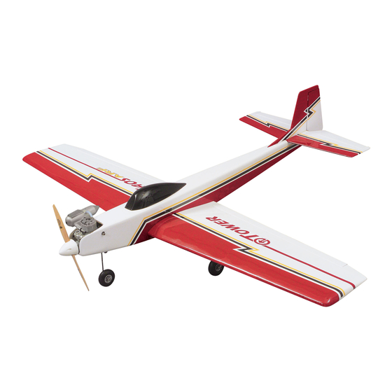
ALMOST READY-TO-FLY RADIO CONTROLLED MODEL AIRPLANE
WINGSPAN: 60 IN.
LENGTH: 50 IN.
WING AREA: 660 SQ. IN.
WEIGHT: 5.5 LBS.
WING LOADING: 19.2 OZ./SQ. FT.
Tower Hobbies
guarantees this kit to be free from defects in both material and workmanship at the date of purchase. This warranty
®
does not cover any component parts damaged by use or modification. In no case shall Tower Hobbies' liability exceed the original
cost of the purchased kit. Further, Tower Hobbies reserves the right to change or modify this warranty without notice.
In that Tower Hobbies has no control over the final assembly or material used for final assembly, no liability shall be assumed nor
accepted for any damage resulting from the use by the user of the final user-assembled product. By the act of using the
user-assembled product, the user accepts all resulting liability.
If the buyers are not prepared to accept the liability associated with the use of this product, they are advised to return this kit
immediately in new and unused condition to the place of purchase.
© Copyright 2000 V1.0
ASSEMBLY INSTRUCTIONS
WARRANTY
™
TOWZ1149 for TOWA1100
Advertisement
Table of Contents

Subscribe to Our Youtube Channel
Related Manuals for Tower Hobbies Tower Trainer 40 ARF


Summary of Contents for Tower Hobbies Tower Trainer 40 ARF
-
Page 1: Assembly Instructions
Further, Tower Hobbies reserves the right to change or modify this warranty without notice. In that Tower Hobbies has no control over the final assembly or material used for final assembly, no liability shall be assumed nor accepted for any damage resulting from the use by the user of the final user-assembled product. -
Page 2: Table Of Contents
Masking Tape (Required for Construction) you and other first-time radio control modelers, the Tower Hobbies Sandpaper (Coarse, Medium, Fine Grit) Tower Trainer 40 ARF offers nearly all the excitement of piloting a Great Planes Easy Touch Bar Sanders (or Similar) ™... -
Page 3: Accessories Required To Complete Your Tower Trainer 40
Replacement trainer kit options are limited to flat-bottom wing trainer models and makes available from Tower Hobbies and one replacement per customer. The Tower Trainer 40 ARF is a great trainer and we are pleased to make O.S. .40 FX SuperTigre ®... -
Page 4: Parts List
Before assembly match the parts in the photo with the parts in the kit. Check off each part as it is located. If any parts are missing or damaged, consult Tower Hobbies Order Assistance (see back cover page for phone numbers). Note: All Parts Are 1 Piece Unless Otherwise Stated. -
Page 5: Wing Assembly
Special Note: PREPARING THE WING SERVO CAVITY It is suggested to charge your radio system before starting to build. Following the manufacturer‘s instructions, connect your transmitter and receiver batteries to the system‘s charger. This way the radio will be ready when it is time to install and test the radio components. WING ASSEMBLY MARK THE CENTERLINE ON THE JOINER 4. - Page 6 GLUE THE JOINER CAVITY ASSEMBLE THE SERVO TRAY 7. Mix 1/2 oz. (14ml) of 30-minute epoxy. Use a mixing stick or epoxy brush to apply epoxy to all four sides of the joiner cavity. 11. Glue the balsa aileron servo mounting blocks onto the aileron Insert the joiner into the cavity up to the centerline marked on the servo tray using either 6-minute epoxy or medium CA.
-
Page 7: Fuselage Assembly
INSTALL THE SERVO TRAY INSTALL THE PUSHRODS 14. Mix 1/8 oz. (3.5ml) of 6-minute epoxy to glue the servo tray to the bottom side of the wing. Apply equal amounts of epoxy to the mounting blocks on both ends of the servo tray. Attach the servo tray 18. - Page 8 INSTALL THE WING MOUNTING DOWELS MARK THE CENTERLINE 2. Insert both wing mounting dowels so they protrude an equal 5. On the top surface of the horizontal stabilizer, measure to find amount on both sides of the fuselage. Mix 1/4 oz. (7ml) of 30-minute the exact center from side to side.
- Page 9 MARK THE STABILIZER LOCATION INSTALL THE VERTICAL FIN 90˚ 90˚ 11. Test fit the vertical fin into the slot on the top of the fuselage. Sand the edges of the slot if necessary for a snug fit. When fit 8. With the stabilizer properly aligned, use a felt-tip pen to trace properly the bottom of the vertical fin will rest on the top of the around the tail of the airplane on the top and bottom of the horizontal stabilizer.
-
Page 10: Landing Gear Installation
INSTALL THE STEERING PUSHROD LANDING GEAR INSTALLATION LOCATE THE LANDING GEAR CHANNEL 1. On the bottom of the fuselage, there is a channel for the main 4. Attach the “Z” bend of the wire to the hole on the steering arm. landing gear. -
Page 11: Fuel Tank Installation
INSTALL THE WHEELS INSTALL THE CLUNK 7. Slide the wheels onto the axles, making sure that they spin 2. Locate the metal fuel pick-up weight (often referred to as the freely on the axles. If not, drill the hole in the wheel out until it can "clunk") and the 4-1/4"... -
Page 12: Engine Installation
ATTACH THE FUEL LINES remaining screws and washers. Pass the screws through the engine mount pads. The screws then go through the mount, passing in front of and behind the engine mounting flange. The pads will be resting on the top of the engine’s mounting flanges. The 4mm nuts are then placed into the recesses on the bottom of the engine mount. -
Page 13: Radio Installation
ATTACH THE FUEL LINES INSTALL THE SERVOS IN THE FUSELAGE 6. Attach the fuel lines to the engine. The line marked with the “V” 2. Route the servo wires forward. Drill 1/16" (1.5mm) pilot holes for vent should be attached to the muffler. The other line will be for the servo mounting screws. - Page 14 BENDING THE ELEVATOR PUSHROD SECURE THE ELEVATOR CONTROL SCREW 8. Slide a 3mm washer onto the screw from the bottom. Thread a 3mm nut onto the screw. Tighten the screw, but not too tight as to crush the underlying wood. Use threadlock on the nut to prevent loosening. INSTALL THE ELEVATOR CONTROL HORN 5.
- Page 15 SECURE THE RUDDER CONTROL SCREW CONNECT THE RUDDER PUSHROD 12. Slide a 3mm washer onto the screw from the bottom. Thread a 15. Attach a clevis to a pushrod. Attach the clevis to the rudder 3mm nut onto the screw. Tighten the screw, but not too tight as to crush control horn.
- Page 16 CONNECT THE ELEVATOR PUSHROD CONNECT THE STEERING PUSHROD 22. Slide the steering pushrod wire though the Screw-Lock Pushrod Connector. With the rudder servo in its neutral position, center the nose wheel so that the airplane will be able to taxi forward in a straight line.
-
Page 17: Radio System Set-Up
CONNECT THE AILERON PUSHRODS top of the fin. Adjust the trimmed servo arm until there is a slight amount of tension on the antenna wire. The rubber band should be partially stretched. Note: Never push a pin through the antenna or trim off the excess wire. -
Page 18: Balance Your Model
ADJUST THE THROTTLE If you need more control movement, you should move the clevis to 2. For added safety and convenience, the throttle should be set up a hole closer to the control surface or you can move the rod at the so that the engine can be stopped using the throttle trim. -
Page 19: Preparing To Fly Your Tower Trainer 40
flights and when you become more acquainted with your Tower BALANCE THE PROPELLER Trainer, you may wish to experiment by shifting the balance up to 1/4" Balance your propellers carefully before flying. An unbalanced prop [6mm] forward or backward to change its flying characteristics. is the single most significant cause of damaging vibration. -
Page 20: Ama Safety Code
ENGINE SAFETY PRECAUTIONS Radio control Note: Failure to follow these safety precautions may result in severe 1. I will have completed a successful radio equipment ground check injury to yourself and others. before the first flight of a new or repaired model. •... - Page 21 TAXIING Your first flights should consist of mostly straight and level flight with Start the engine and set the throttle trim for a slow, steady idle. Have gentle turns to keep the model over the field. These flights will give you your instructor or a helper hold the plane while you work the practice at coordinating your control inputs and maintaining the controls.
-
Page 22: Some Modeling Terms & Trivia
LANDING Angle Of Attack - The angle that the wing penetrates the air. As the angle of attack increases so does lift and drag, up to a point. ARF - A prefabricated model - Almost Ready to Fly. Apply Up Elevator. Buddy Box - Two similar transmitters that are wired together with a “trainer cord.”... - Page 23 Electric Starter - A hand-held electric motor used for starting a wire filament inside the plug is kept hot by the “explosions” in the model airplane engine. Usually powered by a 12-volt battery. engine’s cylinder. See next heading and “idle bar plug.” Elevator - Hinged control surface located at the trailing edge of the Glow Plug Clip/Battery - A 1.2-volt battery, which is connected to horizontal stabilizer, which provides control of the airplane about...
- Page 24 pitch or angle of the blades. The 6 represents the distance the Transmitter (Tx) - The hand-held radio controller. This is the unit that propeller will move forward in one revolution, in this case 6”. sends out the commands that you input. Re-Kitting Your Airplane - Changing your finished model back into a Touch-And-Go - Landing and taking off without a pause.
Need help?
Do you have a question about the Tower Trainer 40 ARF and is the answer not in the manual?
Questions and answers