Table of Contents
Advertisement
To w e r
®
Hobbies
guarantees
this kit to be
free from defects
in both material and
workmanship
at
the
date of purchase. This
warranty does not cover any
component parts damaged by
use or modification. In no case shall
Tower Hobbies' liability exceed the
original cost of the purchased kit. Further,
Tower Hobbies reserves the right to change
or modify this warranty without notice.
In that Tower Hobbies has no control over the final
assembly or material used for final assembly, no
liability shall be assumed nor accepted for any damage
resulting from the use by the user of the final user-assembled
product. By the act of using the user-assembled product, the
user accepts all resulting liability.
If the buyer is not prepared to accept the liability associated with the
use of this product, the buyer is advised to return this kit immediately in
new and unused condition to the place of purchase.
To make a warranty claim send the defective part or item to Hobby Services at
the address below:
Hobby Services • 3002 N. Apollo Dr. Suite 1 • Champaign IL 61822 • USA
Include a letter stating your name, return shipping address, as much contact information as
possible (daytime telephone number, fax number, e-mail address), a detailed description of
the problem and a photocopy of the purchase receipt. Upon receipt of the package the problem
will be evaluated as quickly as possible.
®
© 2017 Tower Hobbies.
A subsidiary of Hobbico, Inc.
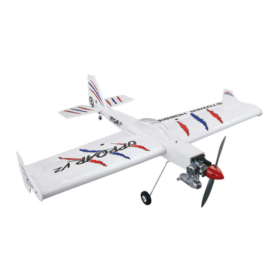
I N S T R U C T I O N M A N U A L
WINGSPAN
47.6 in [1210mm]
LENGTH
48.1 in [1222mm]
4.6– 4.7lbs [2064–2133g]
WING LOADING
16– 17 oz/ft
READ THROUGH THIS MANUAL
.46 EP ARF
WING AREA
630.8 in
[40.7 dm
]
2
2
WEIGHT
2
[51– 52 g/dm
2
]
BEFORE STARTING CONSTRUCTION.
IT CONTAINS IMPORTANT INSTRUCTIONS
AND WARNINGS CONCERNING THE
ASSEMBLY AND USE OF THIS MODEL.
TOWER HOBBIES
POWER
Glow: .46 cu.in. 2-stroke
Electric: 1.70 in [42mm] diameter,
925 W, Hitec Energy Sport 80 ESC
RADIO
4 – 5 channels
Champaign, Illinois
(217) 398-8970 ext. 6
airsupport@hobbico.com
TOWA2040 v1.1
Advertisement
Table of Contents

Subscribe to Our Youtube Channel
Related Manuals for Tower Hobbies Uproar V2 .46 EP ARF


Summary of Contents for Tower Hobbies Uproar V2 .46 EP ARF
-
Page 1: Tower Hobbies
Tower Hobbies reserves the right to change or modify this warranty without notice. READ THROUGH THIS MANUAL In that Tower Hobbies has no control over the final assembly or material used for final assembly, no BEFORE STARTING CONSTRUCTION. liability shall be assumed nor accepted for any damage... -
Page 2: Table Of Contents
For the latest technical updates or manual corrections, fi nd Glow Engine the Uproar V2 ARF on the Tower Hobbies web site at www. towerhobbies.com. If there is new technical information or The Uproar V2 is suited for a .46 2-stroke glow. The O.S. -
Page 3: Lipo Battery Charger
Mixing cups (GPMR8056) in the Kit Contents list. Mixing sticks (GPMR8055) Tower Hobbies Product Support Threadlocker thread locking cement (GPMR6060) 3002 N Apollo Drive, Suite 1 Ph: (217) 398-8970, ext. 6... -
Page 4: Kit Contents
KIT CONTENTS 1. Fuselage 6. Fuel Tank 11. Nylon Hardware 16. Spinner 2. Wing 7. Engine Mount Hardware 12. Tail Gear Hardware 17. Vertical Stabilizer 3. Wing 8. Wing Tip Plates 13. Fastener Hardware 18. Wing Tube 4. Canopy 9. Horizontal Stabilizer 14. -
Page 5: Assemble The Wing
2. Optional: Three or four pinholes can be punctured through the covering between each rib in the bottom of the horizontal stabilizer, the elevators and ailerons, and in one side of the vertical stabilizer and rudder. This will allow 5. NOTE: The procedure for preparing the holes in wood heated, expanding air to escape while tightening covering. - Page 6 3. Rejoin the aileron to the wing with the hinges – as you close the hinge gap make sure the hinges remain centered and make sure the tip of the aileron is even with the tip of the wing. 2. Cut the covering from the servo mount in the bottom of the wing –...
-
Page 7: Hook Up The Ailerons
5. After the CA has hardened fl ex the aileron up and down and pull hard to make sure the hinges are secure. Continue with this wing, or go back to step 1 and hinge the other aileron. Hook Up the Ailerons 4. - Page 8 6. Thread a 4" [100 mm] pushrod onto a clevis until a small portion of the threads appear through the clevis as shown. 9. With the aileron and servo arm centered, mark the pushrod where it crosses the hole in the servo arm. 90-Degree 1/16"...
-
Page 9: Assemble The Fuselage
13. While the servo is still operational move the aileron up and down to check for smooth movement. Make any 3. Also cut the covering from both sides over the wing adjustments necessary. tube holes, the alignment peg holes, the slots for the wing retainers and for the aileron servo wires. - Page 10 the low side until the stab aligns with the wing – it shouldn’t take much sanding and proceed in small increments. Once the saddle is adjusted all that should be required is a small amount of weight to hold down the high side. Trailing Edge of Vertical Stabilizer and End of...
- Page 11 C. Hold the line with the tape to one corner of the stab. 11. Also mark the top and bottom of the fuselage onto the Swing the line over to the corner on the other end of the top and bottom of the stab. stab.
-
Page 12: Glue In The Horizontal & Vertical Stabilizers
13. Use a pin to puncture the covering on both sides of the 2. Mix up approximately 1/4 oz. of 30-minute epoxy. Apply stab just inside the lines you marked. Wipe away the ink lines epoxy to the top and bottom of the stab over the pinholes with a paper towel square dampened with denatured alcohol. -
Page 13: Attach The Elevator And Rudder
1. Tape a layer of 1/4" RC foam around your receiver battery. 2. Applying the same procedures used for hinging the ailerons to the wings, join the elevators to the stab with the hinges and permanently glue them in with thin CA. (If you’ve poked pinholes in one side of the covering over the elevators be sure to put those sides down.) 3. -
Page 14: Hook Up The Elevator And Rudder
Hook Up the Elevator and Rudder 6. Temporarily fi t the rudder to the fi n and fuselage with the hinges. Make the rudder pushrod the same way you made the elevator pushrods, but don’t cut the wire. Slide the pushrod into the fuselage, align the horn over the rudder 1. -
Page 15: Install The Power System
2. Drill 1/16" [1.6 mm ] pilot holes through the “X” marks. Then, enlarge the holes with a 5/32" [4 mm ] drill. 6. To adjust the elevator pushrods and tighten the elevator pushrod link, again with the radio on and the servo powered, use a 1.5mm hex driver to fi rst tighten the middle set screw locking the pushrod link to the pushrod. -
Page 16: Mount The Glow Engine
5. Apply a strip of the rougher, “hook” side of adhesive- back hook-and-loop material (not included) to the top of the 8. Connect the ESC to the motor and place the ESC in battery tray and apply a strip of the softer, “loop” side to the the compartment aft of the battery compartment ahead of bottom of your battery. - Page 17 2. Drill 1/16" [1.6 mm] pilot holes through the “ ” marks. 5. Temporarily mount the engine mount with engine to Then, enlarge the holes with a 3/16" [ 5 mm] drill. the fi rewall with four M4 x 25 Phillips screws and M4 lock 3.
-
Page 18: Hook Up The Throttle
7. Remove the engine from the engine mount. You may also 2. Mount the throttle servo to the throttle servo mount. remove the mount, or leave it in position. Drill 1/16" [1.6 mm] pilot holes through the marks you made for the rear engine bolts. -
Page 19: Install The Fuel Tank
Install the Fuel Tank 1. Fit a 3" [ 75 mm ] piece of medium fuel line (not included) onto the straight pickup tube in the fuel tank stopper. Then, add the clunk to the line. 5. Install and cut the throttle pushrod to the correct length. Then, connect it to the carburetor arm and the screw-lock 2. -
Page 20: Final Radio Installation
4. You may tape the straps across the bottom of the tray so they won’t fall off, then remove the tank and install the tray in the fuselage with four M3 x 10 button-head Phillips screws. 2. Connect 6" [ 150 mm ] servo extensions to the receiver for the aileron servos. -
Page 21: Mount The Tail Gear
Mount the Tail Gear 3. Cut the Main landing gear template from the back of the manual. 1. Place the tail gear mount on the bottom of the fuselage with the vertical part of the tail gear wire centered over the rudder hinge line. -
Page 22: Mount The Canopy
5. Slide the brackets over the tiller arm portion of the tail Mount the Canopy gear wire and onto the rudder. Drill 1/16" [1.6 mm ] holes through the brackets and the rudder. Then, thread in two Curved scissors for cutting out RC car bodies is best for more M 2.5 x 15 screws. -
Page 23: Attach The Side-Force Generators
8. Position the canopy and hold it down with tape until 3. Supporting the inner edge of the canopy as you sand, the glue dries. use a bar-sander with coarse sandpaper to smooth the edges and trim the high spots from around the base of the canopy. Attach the Side-Force Generators 4. -
Page 24: Prepare The Model For Flight
4. If using the 3D throws, a high volume of negative PREPARE THE MODEL FOR FLIGHT exponential is desirable on 3D rates – approximately -60% is a good place to start for each surface. Set the Control Throws 5. While working with radio setup and programming CAUTION: If you’ve installed a brushless motor, the propeller (and before the propeller has been mounted for brushless should not yet be installed. -
Page 25: Balance The Model Laterally
engines that have a 1/4" prop shaft and the second “step” PREFLIGHT on the reamer is good for the RimFire .32 with a 5/16" prop shaft. The spinner cone may be trimmed carefully with a Engine/Motor Safety Precautions hobby knife with a #11 blade. Glow engine setups should be balanced with an empty fuel tank. -
Page 26: Battery Precautions
a little less than 20A through a “normal” fl ight. This is a Before mounting the motor and setting up the ESC and suitable propeller choice and fl ies the Uproar V2 well. Another battery, read the following important battery precautions: suitable propeller choice is the APC 14 x 7 which provides IMPORTANT: If using multiple battery packs that are slightly more thrust at the expense of a little speed. -
Page 27: Range Check
2) I will not fl y my model aircraft higher than approximately 400 feet within 3 miles of an airport without notifying the 11.1V airport operator. I will give right-of-way and avoid fl ying in the (3-Cell) proximity of full-scale aircraft. Where necessary, an observer shall be utilized to supervise fl ying to avoid having models fl y in the proximity of full-scale aircraft. -
Page 28: Flying
The Uproar V2 doesn’t have any particular fl ight characteristics like any other regular sport model. On 3D rates you better that you need to be cautioned about ahead of time. In-spite remain calm and be quick to react because the Uproar V2 responds quickly (even with “gobs”...
Need help?
Do you have a question about the Uproar V2 .46 EP ARF and is the answer not in the manual?
Questions and answers