Table of Contents
Advertisement
Quick Links
Advertisement
Table of Contents

Summary of Contents for Integra SMART THERMOSTAT
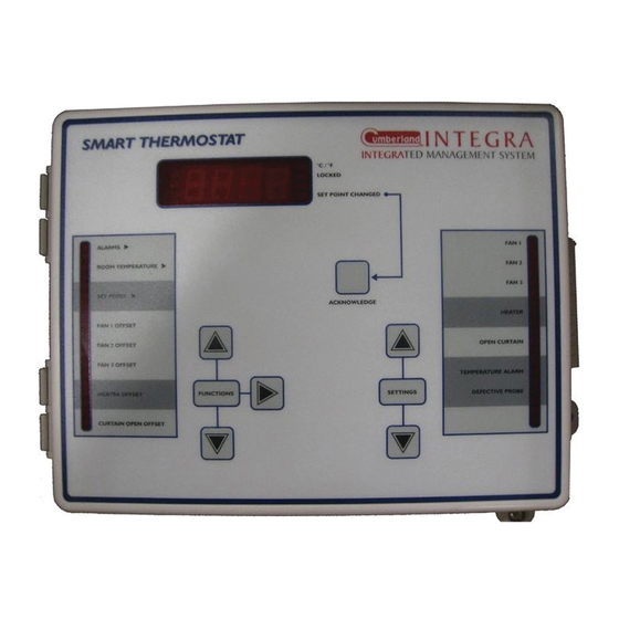
- Page 1 Thermostat Controller SMART THERMOSTAT USER'S MANUAL...
-
Page 2: Table Of Contents
AIR INTAKE: CURTAIN & VENT DOORS ......25 ALARMS ..............27 Temperature Alarms ............. 27 Set Point Alarms ..............27 Adjusting the Alarm Settings ..........28 TEST MODE ............... 29 TROUBLESHOOTING GUIDE ......... 30 TECHNICAL SPECIFICATIONS ........32 SMART THERMOSTAT rev.01... -
Page 3: Precautions
DO NOT SPRAY WATER ON THE CONTROLLER! FOR CUSTOMER USE Enter the serial number located on the side of the controller below for future reference. Model number: SMART THERMOSTAT Serial number: SMART THERMOSTAT rev.01... -
Page 4: Features
AUTOMATIC THERMOSTAT ADJUSTMENT The SMART THERMOSTAT reads the set point of the main temperature controller on a regular basis. This way, if the main controller fails, the SMART THERMOSTAT continues running using the previous valid set point provided by the main controller. - Page 5 TEMPERATURE CURVE When the SMART THERMOSTAT is used as a stand-alone unit (i.e. when there is no main temperature controller), it can automatically change the temperature set point over a given period of time in accordance with the user's requirements by specifying a temperature curve with up to six dif- ferent points.
-
Page 6: Controller's Status Leds
TURNS ON WHEN THE THERMOSTAT HEATER CONTROLLER ACTIVATES THE HEATING OUTPUT. TURNS ON WHEN THE THERMOSTAT OPEN CURTAIN CONTROLLER OPENS THE CURTAIN. TURNS ON WHEN A TEMPERATURE TEMPERATURE ALARM ALARM IS DETECTED. DEFECTIVE PROBE FLASHES WHEN A DEFECTIVE PROBE IS DETECTED. SMART THERMOSTAT rev.01... -
Page 7: Internal Switches
When the controller is shipped from 9 10 11 12 the factory, all the switches are set to OFF. UNLOCKED PARAMETERS LOCKED PARAMETERS FAHRENHEIT DEGREES CELSIUS DEGREES PROBE 2 DISABLED PROBE 2 ENABLED 4-12 RESERVED SMART THERMOSTAT rev.01... -
Page 8: Installation
NC terminal. ALL WIRING MUST BE DONE BY AN AUTHORIZED ELECTRICIAN AND MUST COMPLY WITH APPLICABLE CODES, LAWS AND REGULATIONS. BE SURE POWER IS OFF BEFORE DOING ANY WIRING TO AVOID ELECTRI- WARNING CAL SHOCKS AND EQUIPMENT DAMAGE. SMART THERMOSTAT rev.01... -
Page 9: Temperature Probes
Do not ground the shielding. It is preferable to solder the cable joint to ensure a proper contact between the two cables. CAUTION: Do not run probe cables next to other power cables. When crossing over other cables, cross at 90°. SMART THERMOSTAT rev.01... - Page 10 If the probe is defective, the letters "PR#" are displayed, alternating with the on/off state of the probe and the letter "P". SMART THERMOSTAT rev.01...
-
Page 11: Changing The Parameter Settings
(i) The current offset for fan 2 flashes on the display, alternating with "Oft". (ii) If, after about 10 seconds, no action is taken by the user, the absolute temperature value is displayed, alternating with "Abs". In this case, the absolute value is: Set Point + fan 2 offset. SMART THERMOSTAT rev.01... -
Page 12: Locking The Parameter Settings
When the settings are locked, only the temperature set point can be modified (as long as the temperature curve is deactivated). To lock the parameter settings, set internal switch # 1 to ON. O F F To unlock the parameter settings, set internal switch # 1 to OFF. SMART THERMOSTAT rev.01... -
Page 13: Temperature Settings
F (-40.0 C to 48.9 Viewing Room Temperature The SMART THERMOSTAT displays the average room temperature of the main temperature controller. If the communication link between both con- trollers becomes disrupted, the SMART THERMOSTAT will then display the average temperature value measured by its activated probes. - Page 14 For each additional probe, press the second functions push-button. The letters "Pr x" are displayed, alternating with the temperature reading from probe x and the on/off state of the probe. Note: The display returns to the average room temperature after one minute. SMART THERMOSTAT rev.01...
- Page 15 "Hi". NOTE: If you let the display flash for more than 10 seconds, the controller resets the minimum and maximum temperatures currently in memory (the display stops flashing to indicate that the reset has been done). SMART THERMOSTAT rev.01...
-
Page 16: Temperature Set Point
(see ALARMS), the SMART THERMOSTAT starts running as a stand-alone unit and uses the previous valid temperature set point transmitted by the temperature con- troller. -
Page 17: Temperature Curve
Certain restrictions apply to reduce the risk of errors: - The highest possible day number is 99. - Decreasing day numbers are not allowed. - Increasing temperatures are not allowed. - The temperature variation cannot exceed 3°F (1.6°C) per day. SMART THERMOSTAT rev.01... - Page 18 SMART THERMOSTAT Specifying the Curve Points The SMART THERMOSTAT only uses this function when it operates as a stand-alone unit (i.e. when no temperature controller is detected). Set the function to SET POINT using the function selector buttons. The current temperature set point flashes on the display.
- Page 19 OFF flashes (thirteen clicks). Press the up-arrow adjustment button. The word ON is displayed, indicating that the temperature curve is now activated. Press the second functions push-button to complete the sequence. SMART THERMOSTAT rev.01...
- Page 20 ON flashes (fourteen clicks). Press the down-arrow adjustment button. The word OFF flashes on the display indicating that the tem- perature curve is now deactivated. Press the second functions push-button to complete the sequence. SMART THERMOSTAT rev.01...
-
Page 21: Ventilation
SMART THERMOSTAT VENTILATION The SMART THERMOSTAT controls 3 fan outputs which are activated when the room temperature reaches their start temperature (start tem- perature = set point + fan offset); they stop running when the room temperature decreases of 1°F (0,56°C) below their respective start tem- perature. - Page 22 Set the function to FAN 1, 2 or 3 – OFFSET, using the function selec- tor buttons. The current offset for the selected fan output is displayed, alternating with the letters “Oft”. Use the adjustment buttons to adjust the fan offset to the desired value. SMART THERMOSTAT rev.01...
-
Page 23: Heating
SMART THERMOSTAT HEATING The SMART THERMOSTAT controls 1 heating output. This output is acti- vated when the temperature falls and reaches the set point - Heater Offset; the heating output stops when the room temperature increases and reaches Set Point - Heater Offset + 1°F (0,56°C). The following graphic sums up the situation. - Page 24 C and 22.2 Set the function to HEATER OFFSET using the function selector but- tons. The current heating offset is displayed, alternating with the let- ters "OFT". Use the adjustment buttons to adjust the offset to the desired value. SMART THERMOSTAT rev.01...
-
Page 25: Air Intake: Curtain & Vent Doors
SMART THERMOSTAT AIR INTAKE: CURTAIN & VENT DOORS The SMART THERMOSTAT opens an air intake (curtain or vent doors) when the temperature gets too high. It starts opening the actuator continuously when the room temperature reaches the set point + curtain open offset. - Page 26 The curtain opening offset is the number of degrees above the set point at which the thermostat controller starts opening the curtain continuously; the SMART THERMOSTAT disables the curtain's closing relay while it opens the curtain. The offset can be adjusted between 0.5 F and 40.0...
-
Page 27: Alarms
When this type of alarm is set off, the thermostat controller asks the user to acknowledge the alarm condition. In the meanwhile, the thermostat controller operates as a stand-alone unit using the previous valid set point that was transmitted by the main temperature controller. SMART THERMOSTAT rev.01... -
Page 28: Adjusting The Alarm Settings
Press the second functions push-button. The current high alarm offset flashes on the display, alternating with the word "HI.AL". Use the adjustment buttons to set the high alarm offset to the desired value. SMART THERMOSTAT rev.01... -
Page 29: Test Mode
Set the function to ROOM TEMPERATURE using the function selector buttons. The current room temperature is displayed. Press and hold the second functions push-button for 3 seconds. NOTE: If no user activity is recorded after 4 minutes in test mode, the controller resumes normal operation. SMART THERMOSTAT rev.01... -
Page 30: Troubleshooting Guide
Do not route probe cables and other power cables through the same electrical knockout. Do not run probe cables next to other power cables. When crossing other power cables, cross at 90°. SMART THERMOSTAT rev.01... - Page 31 The controller is defective. Listen to see if there is a clicking sound when the stage or heater pilot light turns on. If there is no clicking sound, contact your distributor to repair the controller. SMART THERMOSTAT rev.01...
-
Page 32: Technical Specifications
-40.0° to 120.0°F (-40.0° to 48.9°C). Accuracy: 1.8 F (1 C) between and 95 F (5 and 35 Enclosure: ABS, moisture and dust-tight. The room temperature where the controller is located MUST ALWAYS REMAIN BETWEEN 32 AND 104 F (0 AND 40 SMART THERMOSTAT rev.01... - Page 33 M 890-00048 rev. 01 REV. 02...
Need help?
Do you have a question about the SMART THERMOSTAT and is the answer not in the manual?
Questions and answers