turck PS310 Series Instructions For Use Manual
Pressure sensors
Hide thumbs
Also See for PS310 Series:
- Quick start manual (12 pages) ,
- Instructions for use manual (45 pages)

Related Manuals for turck PS310 Series


Summary of Contents for turck PS310 Series
- Page 1 Your Global Automation Partner PS310… | PS510… Pressure Sensors Instructions for Use...
- Page 2 Hans Turck GmbH & Co. KG | T +49 208 4952-0 | F +49 208 4952-264 | more@turck.com | www.turck.com...
-
Page 3: Table Of Contents
Contents About these Instructions........................ 5 Target groups........................ 5 Explanation of symbols used .................. 5 Other documents ...................... 5 Feedback about these instructions................ 5 Notes on the Product ......................... 6 Product identification..................... 6 Scope of delivery ...................... 6 Legal requirements...................... 6 Manufacturer and service .................... - Page 4 Contents 10 Troubleshooting .......................... 27 11 Maintenance............................ 28 12 Repair.............................. 28 12.1 Returning devices...................... 28 13 Disposal .............................. 28 14 Technical Data........................... 29 Hans Turck GmbH & Co. KG | T +49 208 4952-0 | F +49 208 4952-264 | more@turck.com | www.turck.com...
-
Page 5: About These Instructions
This symbol denotes actions that the user must carry out. RESULTS OF ACTION This symbol denotes relevant results of actions. Other documents Besides this document the following material can be found on the Internet at www.turck.com: Data sheet Quick-Start Guide IO-Link parameters manual... -
Page 6: Notes On The Product
Pressure sensor Quick-Start Guide Legal requirements The device is subject to the following EC directives: 2014/30/EU (electromagnetic compatibility) 2011/65/EU (RoHS Directive) Hans Turck GmbH & Co. KG | T +49 208 4952-0 | F +49 208 4952-264 | more@turck.com | www.turck.com... -
Page 7: Manufacturer And Service
45472 Mülheim an der Ruhr Germany Turck supports you with your projects, from initial analysis to the commissioning of your applic- ation. The Turck product database contains software tools for programming, configuration or commissioning, data sheets and CAD files in numerous export formats. You can access the product database at the following address: www.turck.de/products... -
Page 8: For Your Safety
The device may only be used in accordance with applicable national and international regu- lations, standards and laws. The maximum permissible overpressure must not be exceeded. Hans Turck GmbH & Co. KG | T +49 208 4952-0 | F +49 208 4952-264 | more@turck.com | www.turck.com... -
Page 9: Product Description
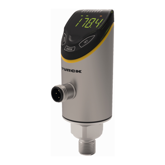
Product Description The pressure sensors of the PS+ series are contained in a metal housing with a display and are available with different process connections. The housing can also be aligned and fastened as required after mounting. All devices are provided with a metal-bodied M12 connector for con- necting the sensor cable. -
Page 10: Operating Principle
Programming mode enables the setting of all adjustable parameter values. A short press of the [SET] touchpad displays the values of a parameter. Hans Turck GmbH & Co. KG | T +49 208 4952-0 | F +49 208 4952-264 | more@turck.com | www.turck.com... -
Page 11: Output Functions - Switching Output
4.5.5 Output functions – Switching output A window function and a hysteresis function can be set for the switching outputs. Window function The window function is used to teach a switching range in which the switching output takes on a defined switching state. The switching range is defined by an upper and lower limit value. The minimum distance between the limit values is 0.5 % of the nominal pressure range. -
Page 12: Output Functions - Analog Output
The communication parameters are exchanged first of all; the cyclic data exchange of the process data (process data objects) then starts. Hans Turck GmbH & Co. KG | T +49 208 4952-0 | F +49 208 4952-264 | more@turck.com | www.turck.com... -
Page 13: Technical Accessories
In addition to the above connection cables, Turck also offers other cable types for specific ap- plications with the correct terminals for the device. More information on this is provided in the Turck product database at www.turck.de/products... -
Page 14: Installing
If the zero point is offset, an offset value can be set via the CoF parameter (see chapter “Settings”). Hans Turck GmbH & Co. KG | T +49 208 4952-0 | F +49 208 4952-264 | more@turck.com | www.turck.com... -
Page 15: Connecting
Connecting „ Connect the female connector of the connection cable to the male connector of the sensor. „ Connect the open end of the connection cable to the power supply and/or processing units. Wiring diagrams 1 L + 3 L – 2 out 2 switch 4 out 1 switch/IO-Link Fig. 10: Pin layout PS…2UPN…... -
Page 16: Commissioning
Commissioning Commissioning The device is operational automatically once the power supply is switched on. Hans Turck GmbH & Co. KG | T +49 208 4952-0 | F +49 208 4952-264 | more@turck.com | www.turck.com... -
Page 17: Operation
Operation LED status indications – Operation Indication Meaning Green Device is operational Green flashing IO-Link communication Error Green Display in bar Green Display in psi Green Display in kPa Green Display in MPa MISC Green Other display unit Yellow Device locked Yellow flashing “Lock/unlock”... -
Page 18: Display Indications - Diagnostic Messages
Value outside of the measuring range, > 5 % of full scale above limit Value outside of the measuring range, > 5 % of full scale below limit Hans Turck GmbH & Co. KG | T +49 208 4952-0 | F +49 208 4952-264 | more@turck.com | www.turck.com... -
Page 19: Setting
Setting The device can be assigned parameters as follows: Setting via touchpad Setting via IO-Link The following flow charts illustrate the operating steps during the teach-in process. Fig. 16: Overview of the teach main menu V01.00 | 2020/01... - Page 20 Setting Fig. 17: Overview of the teach EF menu Hans Turck GmbH & Co. KG | T +49 208 4952-0 | F +49 208 4952-264 | more@turck.com | www.turck.com...
- Page 21 Fig. 18: Overview of the menu navigation V01.00 | 2020/01...
-
Page 22: Setting Via Touchpads
Protect the sensor with a password: Select PASS in the EF menu. Change values via [SET]. Use [MODE] to navigate between the four digits of the password. Hans Turck GmbH & Co. KG | T +49 208 4952-0 | F +49 208 4952-264 | more@turck.com | www.turck.com... -
Page 23: Parameters In The Main Menu
9.1.4 Parameters in the main menu Explanation Options Function Display unit mBar Torr = mmHg (0 °C) Inch of water (60 °F) Inch of water (39 °F) Foot of water (39 °F) Inch of Hg (60 °F) Inch of Hg (32 °F) mH20 (16 °C) mH20 (4 °C) Ud10 kg/Cm Function of output 1... -
Page 24: Parameters In The Ef Submenu (Extended Functions)
Switch delay of rP1 0…60 s in increments of 0.1 s (0 = delay time not active) Hans Turck GmbH & Co. KG | T +49 208 4952-0 | F +49 208 4952-264 | more@turck.com | www.turck.com... - Page 25 Explanation Options Function Switch delay of FH1 0…60 s in increments of 0.1 s (0 = delay time dFH1 not active), only available with window mode Fno or Fnc dFL1 Switch delay of FL1 0…60 s in increments of 0.1 s (0 = delay time not active), only available with window mode Fno or Fnc Switch delay of SP2...
-
Page 26: Setting Via Io-Link
All the parameters can be changed in IO-Link mode via the controller during commissioning as well as during operation. In SIO mode the device operates according to the last setting made in IO-Link mode. Hans Turck GmbH & Co. KG | T +49 208 4952-0 | F +49 208 4952-264 | more@turck.com | www.turck.com... -
Page 27: Troubleshooting
Troubleshooting If the device does not function as expected, first check whether ambient interference is present. If there is no ambient interference present, check the connections of the device for faults. If there are no faults, there is a device malfunction. In this case, decommission the device and replace it with a new device of the same type. -
Page 28: Maintenance
Disposal The devices must be disposed of correctly and must not be included in normal household garbage. Hans Turck GmbH & Co. KG | T +49 208 4952-0 | F +49 208 4952-264 | more@turck.com | www.turck.com... -
Page 29: Technical Data
Technical Data Type code PS 310 PS 510 Pressure range Sensor-dependent Pressure type See data sheet Outputs Transistor switching output, analog outputs and IO-Link (freely configurable) IO-Link COM2 38.4 kBaud frame type 2.2 Current output (0) 4…20 mA Voltage output 0…10 V, 0…5 V, 1…6 V Accuracy of analog output Sensor-dependent... - Page 30 50 x g (11 ms) acc. to EN 60068-2-27 Type of display 4-digit 12-segment display, rotatable by 180°. Red or green. Number of touchpads Hans Turck GmbH & Co. KG | T +49 208 4952-0 | F +49 208 4952-264 | more@turck.com | www.turck.com...
- Page 31 Over 30 subsidiaries and over 60 representations worldwide! 100004407 | 2020/01 100004407 www.turck.com...
Need help?
Do you have a question about the PS310 Series and is the answer not in the manual?
Questions and answers