Fujitsu PRIMEQUEST 480 Installation Planning Manual
Hide thumbs
Also See for PRIMEQUEST 480:
- Installation planning manual (142 pages) ,
- System design manual (280 pages) ,
- Installation manual (446 pages)
Table of Contents
Advertisement
Quick Links
Advertisement
Table of Contents

Related Manuals for Fujitsu PRIMEQUEST 480


Summary of Contents for Fujitsu PRIMEQUEST 480
- Page 1 C122-H001-02EN Front Cover INSTALLATION PLANNING MANUAL...
- Page 3 Keep this manual handy for further reference. Fujitsu makes every effort to prevent users and bystanders from being injured or from suffering damage to their property. Use the product according to this manual. ABOUT THIS PRODUCT...
- Page 4 RADIO FREQUENCY INTERFERENCE STATEMENT The following notice is for EU users only. WARNING: This is a product which meets Class A of EN55022. In a domestic environment this product may cause radio interference in which case the user may be required to take adequate measures.
- Page 5 The contens of this manual may be revised without prior notice. The contents of this manual shall not be disclosed in any way or reproduced in any media without the express written permission of Fujitsu Limited. All Rights Reserved, Copyright FUJITSU LIMITED 2005...
- Page 7 Revision History (1/1) Revised section Edition Date Details (Added/ Deleted/ Altered) 2005-07-11 2005-09-15 Entire manual (Altered) • Technical brush-up • Modification of the manual title • Addition of PRIMEQUEST series Section 2.2.1 (1) • Modification of the concept (Altered/Added) of units operational grouping •...
- Page 9 Preface This manual describes requirements and concepts for installation and facility planning for the PRIMEQUEST 480 and 440. Installation and facility planning should be performed together with your assigned Fujitsu representatives according to the instructions provided in this manual. This manual is intended for persons introducing and planning the installation of a PRIMEQUEST server, or those who manage server operations.
- Page 10 • In this manual, it is assumed that two BMMs (optional products) can be connected to a single I/O unit; this is reflected both in the explanations and in the figures included in this manual. At present, however, the PRIMEQUEST 480/400 series supports only connection to one BMM (BMM#0) per I/O unit.
- Page 11 2.4 Input Power Supply Unit Connections ......2-32 2.4.1 PRIMEQUEST 480/440 main unit ......2-32 2.4.2 Cables between PCI_Box and ACS in the extended I/O cabinet .
- Page 12 Contents CHAPTER 3 Precautions Pertaining to Delivery and Installation ..3.1 Elevator Load Requirements ........3.2 Earthquake Preparedness Measures .
-
Page 13: Table Of Contents
External view of the PCI_Box ......Figure 1.9 PRIMEQUEST 480/440 floor plan ......1-14 Figure 1.10 Extended power cabinet floor plan . - Page 14 Figure 2.8 External interface ports in the extended I/O cabinet (connected to PRIMEQUEST 480 unit) ....2-15 Figure 2.9 Input power system diagram for the PRIMEQUEST 440 (standard configuration) .
- Page 15 Figure 3.2 Earthquake-proofing construction method (through-floor anchoring) 3-4 Figure 3.3 Example of installing a PRIMEQUEST 480/440 system by using the earthquake-proofing construction method ... Figure 3.4 Example of installing a PRIMEQUEST 480 system with an extended power cabinet by using the earthquake-proofing construction method .
- Page 16 Table 2.2 Cable list (LAN and other device connection) ....Table 2.3 AC cable specifications for the PRIMEQUEST 480/440 main unit 2-32 Table 2.4 Specifications of the AC cables used between a PCI_Box and ACS in the extended I/O cabinet .
- Page 17 CHAPTER 1 Installation Reference This chapter provides the information required for installing the PRIMEQUEST 480/ 440 server. Equipment Configuration Table 1.1 lists the units that comprise the PRIMEQUEST server and their specifications. Figure 1.1 and Figure 1.4 show a sample system configuration.
-
Page 18: Figure 1.1 Configuration Of Primequest 480 And 440 Main Unit
CHAPTER 1 Installation Reference Top view 738 (29.0) 1100 (43.3) Front view Right-side view Rear view Unit: mm (in.) Figure 1.1 Configuration of PRIMEQUEST 480 and 440 main unit C122-H001-02EN... -
Page 19: Figure 1.2 Configuration Of Primequest 480 And 440 Main Unit
1.1 Equipment Configuration Extended I/O Main unit cabinet Top view 1422 (55.9) 1100 (43.3) Front view Right-side view Unit: mm (in.) Figure 1.2 Configuration of PRIMEQUEST 480 and 440 main unit and extended I/O cabinet C122-H001-02EN... -
Page 20: Figure 1.3 Configuration Of The Primequest 480 Main Unit And The Extended Power Cabinet
CHAPTER 1 Installation Reference Main unit Extended power cabinet Top view 1042 (41.0) 1100 (43.3) Front view Right-side view Unit: mm (in.) Figure 1.3 Configuration of the PRIMEQUEST 480 main unit and the extended power cabinet C122-H001-02EN... -
Page 21: Figure 1.4 Configuration Of The Primequest 480 Main Unit, Extended I/O Cabinet, And The Extended Power Cabinet
1.1 Equipment Configuration Extended I/O Main unit cabinet Extended power cabinet Top view 1726 (67.9) 1100 (43.3) Front view Right-side view Unit: mm (in.) Figure 1.4 Configuration of the PRIMEQUEST 480 main unit, extended I/O cabinet, and the extended power cabinet C122-H001-02EN... -
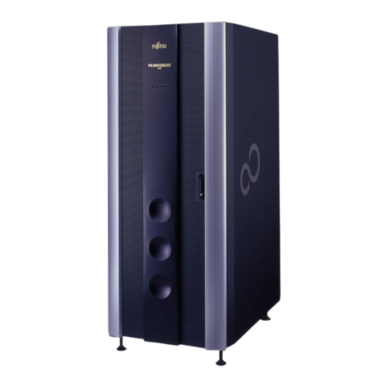
Page 22: Figure 1.5 External View Of The Primequest 480/440 Main Unit
Views of the Units The following figures show different views of the units: External view of the PRIMEQUEST 480/440 main unit (Figure 1.5) External view of the extended power cabinet (Figure 1.6) External view of the extended I/O cabinet (Figure 1.7) External view of the PCI_Box (Figure 1.8) -
Page 23: Figure 1.6 External View Of The Extended Power Cabinet
1.2 Views of the Units Extended power cabinet Top view 329 (12.9) 1100 (43.3) Front view Right-side view Rear view Unit: mm (in.) Figure 1.6 External view of the extended power cabinet C122-H001-02EN... -
Page 24: Figure 1.7 External View Of The Extended I/O Cabinet
CHAPTER 1 Installation Reference Extended I/O cabinet Top view 709 (27.9) Rear view Left-side view Front view Unit: mm (in.) Figure 1.7 External view of the extended I/O cabinet C122-H001-02EN... - Page 25 1.2 Views of the Units Rear view 443 (17.4) Left-side view Top view Right-side view 482 (18.9) Right-side view Unit: mm (in.) Figure 1.8 External view of the PCI_Box C122-H001-02EN...
-
Page 26: Table 1.2 Installation Specifications (Dimensions And Weight)
[kg (lb)] Width Depth Height (*1) PRIMEQUEST 440 main unit 1100 1800 (Model name:MC4A0P111) (29.06) (43.31) (70.87) (1320) PRIMEQUEST 480 main unit 1100 1800 (Model name: MC5A0P111) (29.06) (43.31) (70.87) (1584) Extended power cabinet 1100 1800 (Model name: MC-57DP11, (11.81) (43.31) -
Page 27: Table 1.3 Installation Specifications (Air Conditioning 1)
1.3 Installation Specifications Table 1.3 Installation specifications (air conditioning 1) Temperature and humidity (*1) Exhaust air Operating Stand-by Not operating (*2) Heat flow Maximum Maximum Maximum Product dissipation Remarks /min Temperature Humidity wet bulb Temperature Humidity[ wet bulb Temperature Humidity wet bulb [kJ/Hr] [°C]... -
Page 28: Table 1.5 Installation Specifications (Air Conditioning 2)
8.5 or less 0.15 unit (Synthetic (Synthetic (Type name: MC4A0P111) seismic vibration) seismic vibration) PRIMEQUEST 480 main 70 or less 8.5 or less 5 SBs or 5 unit IO_Units or more (Type name: MC5A0P111) 4 SBs or 4 IO_Units or less... -
Page 29: Table 1.6 Installation Specifications (Power Supplies)
1.3 Installation Specifications Table 1.6 Installation specifications (power supplies) Power supply Power requirement Device Inrush Input voltage Frequency [kVA] Leakage circuit Product Remarks Power current tolerance and current breaker factor [A][Inrush No. of phases tolerance [mA] capacity Operating Stand-by duration] PRIMEQUEST 50/60Hz 0.9 or more... -
Page 30: Figure 1.9 Primequest 480/440 Floor Plan
CHAPTER 1 Installation Reference Equipment Floor Plan The figures in this section show the floor plan for the equipment. PRIMEQUEST 480/440 floor plan (Figure 1.9) Extended power cabinet floor plan (Figure 1.10) Extended I/O cabinet floor plan (Figure 1.11) 640 (25.1) (0.7) -
Page 31: Figure 1.10 Extended Power Cabinet Floor Plan
1.4 Equipment Floor Plan (3.5 (4.7) 250.75 (9.9) 255 (10.0) 300 (11.8) 29 (1.1) 329 (13.0) Front Unit: mm (in.) [Legend] : Interface cable hole : Inlet air area : Leveling pad : Caster * This is a top view of the unit. Figure 1.10 Extended power cabinet floor plan C122-H001-02EN 1-15... -
Page 32: Figure 1.11 Extended I/O Cabinet Floor Plan
CHAPTER 1 Installation Reference 590 (23.2) 45 (1.8) 519 (20.4) 101 (4.0) 478 (18.8) 680 (26.8) 709 (27.9) (1.1) [Legend] Front : Interface cable hole Unit: mm (in.) : Inlet air area : Leveling pad : Caster * This is a top view of the unit. Figure 1.11 Extended I/O cabinet floor plan 1-16 C122-H001-02EN... -
Page 33: Figure 1.12 Service Area For The Primequest 480/440 Main Unit
Service area for the PRIMEQUEST 480/440 main unit and the extended I/O cabinet (Figure 1.13) Service area for the PRIMEQUEST 480 main unit and the extended power cabinet (Figure 1.14) Service area for the PRIMEQUEST 480 Main unit, the extended I/O cabinet, and the extended power cabinet (Figure 1.15) -
Page 34: Figure 1.13 Service Area For The Primequest 480/440 Main Unit
Service area Front Unit: mm (in.) Installation area: 3.9 m (including service area) * This is a top view of the unit. Figure 1.13 Service area for the PRIMEQUEST 480/440 main unit and the extended I/O cabinet 1-18 C122-H001-02EN... -
Page 35: Figure 1.14 Service Area For The Primequest 480 Main Unit
Service area Front Unit: mm (in.) Installation area: 2.9 m (including service area) * This is a top view of the unit. Figure 1.14 Service area for the PRIMEQUEST 480 main unit and the extended power cabinet C122-H001-02EN 1-19... -
Page 36: Figure 1.15 Service Area For The Primequest 480 Main Unit, The Extended I/O Cabinet, And The Extended Power Cabinet
Unit: mm (in.) Installation area: 4.7 m (including service area) * This is a top view of the unit. Figure 1.15 Service area for the PRIMEQUEST 480 Main unit, the extended I/O cabinet, and the extended power cabinet 1-20 C122-H001-02EN... - Page 37 1.6 Floor Plan of Openings in Floor and Template Floor Plan of Openings in Floor and Template This section provides the floor plan for openings in the floor. Templates are provided in section 1.6.2, "Templates," to allow you to plan your configuration before moving equipment.
-
Page 38: Figure 1.16 Symbols Used In Floor Plans And Templates
CHAPTER 1 Installation Reference • Symbols used Figure 1.16 shows the symbols used in the figures for floor plan openings and in the template. Leveling pad Front Service area Figure 1.16 Symbols used in floor plans and templates 1-22 C122-H001-02EN... - Page 39 This section describes the floor plans for openings to accommodate each unit. Floor openings for the PRIMEQUEST 480/440 main unit (Figure 1.17) Floor openings for the PRIMEQUEST 480/440 main unit and the extended I/O cabinet (Figure 1.18) Floor openings for the PRIMEQUEST 480 main unit and the extended power cabinet (Figure 1.19)
-
Page 40: Figure 1.17 Floor Openings For The Primequest 480/440 Main Unit
50% 450 450 Front 81.25 (3.2) 575.5 (22.7) 81.25 (3.2) Unit: mm (in.) [Legend] : Interface cable hole : Inlet air area : Leveling pad : Caster Figure 1.17 Floor openings for the PRIMEQUEST 480/440 main unit 1-24 C122-H001-02EN... -
Page 41: Figure 1.18 Floor Openings For The Primequest 480/440 Main Unit
575.5 (22.7) 81.25 (3.2) 101.25 (4.0) [Legend] Unit: mm (in.) : Interface cable hole : Inlet air area : Leveling pad : Caster Figure 1.18 Floor openings for the PRIMEQUEST 480/440 main unit and the extended I/O cabinet C122-H001-02EN 1-25... -
Page 42: Figure 1.19 Floor Openings For The Primequest 480 Main Unit And
575.5 (22.7) 307 (12.1) 78.25 (3.1) Unit: mm (in.) [Legend] : Interface cable hole : Inlet air area : Leveling pad : Caster Figure 1.19 Floor openings for the PRIMEQUEST 480 main unit and the extended power cabinet 1-26 C122-H001-02EN... -
Page 43: Figure 1.20 Floor Openings For The Primequest 480 Main Unit, The Extended I/O Cabinet, And The Extended Power Cabinet
101.25 (4.0) Unit: mm (in.) [Legend] : Interface cable hole : Inlet air area : Leveling pad : Caster Figure 1.20 Floor openings for the PRIMEQUEST 480 main unit, the extended I/O cabinet, and the extended power cabinet C122-H001-02EN 1-27... -
Page 44: Figure 1.21 Template For The Primequest 480/440 Main Unit
Template for the PRIMEQUEST 480/440 main unit and the extended I/O cabinet (Figure 1.22) Template for the PRIMEQUEST 480 and the extended power cabinet (Figure 1.23) Template for the PRIMEQUEST 480 main unit, the extended I/O cabinet, and the extended power cabinet (Figure 1.24) Front Figure 1.21 Template for the PRIMEQUEST 480/440 main unit... -
Page 45: Figure 1.23 Template For The Primequest 480 And
1.6 Floor Plan of Openings in Floor and Template Front Figure 1.23 Template for the PRIMEQUEST 480 and the extended power cabinet Front Figure 1.24 Template for the PRIMEQUEST 480 main unit, the extended I/O cabinet, and the extended power cabinet C122-H001-02EN 1-29... -
Page 46: Figure 1.25 Cooling Air And Exhaust Flows Of
Cooling Air and Exhaust Flows This section explains the cooling air and exhaust flows of each cabinet. Cooling air and exhaust flows of the PRIMEQUEST 480/440 main unit (Figure 1.25) Cooling air and exhaust flows of the extended power cabinet (Figure 1.26) Cooling air and exhaust flows of the extended I/O cabinet (Figure 1.27) -
Page 47: Figure 1.26 Cooling Air And Exhaust Flows Of The Extended Power Cabinet
1.7 Cooling Air and Exhaust Flows Input section (Power supply section Front view Right-side view : Intake air : Exhaust air Figure 1.26 Cooling air and exhaust flows of the extended power cabinet PCI_Box#7 PCI_Box#6 PCI_Box#5 PCI_Box#4 PCI_Box#3 PCI_Box#2 PCI_Box#1 PCI_Box#0 Left-side view Front view... - Page 48 CHAPTER 1 Installation Reference Front view Top view : Intake air Right-side view : Exhaust air Figure 1.28 Cooling air and exhaust flows of the PCI_Box 1-32 C122-H001-02EN...
- Page 49 CHAPTER 2 Connection Reference This chapter provides cable connection diagrams and lists of the applicable cables. Connection Overview Figure 2.1 shows an overview of equipment cable connections: C122-H001-02EN...
- Page 50 CHAPTER 2 Connection Reference PRIMEQUEST 400 series main unit IOU(Note 1) (x0-8:PRIMEQUEST 480) (x0-4:PRIMEQUEST 440) PCI card type: - LAN interface PCI-x card (x4) - SCSI - Fibre Channel BMC module (x2) USB1.1/2.0 equipment USB2.0 (x2) COM (x1) Console SCSI equipment...
- Page 51 This section provides diagrams of signal-cable connections, lists of applicable cables, and notes on cabling. Basic interfaces and peripherals (Section 2.2.1) LAN and other device connections (Section 2.2.2) Notes on cabling PRIMEQUEST 480/440 (Section 2.2.3) Locations of external interface ports (Section 2.2.4) 2.2.1 Basic interfaces and peripherals Figure 2.2 shows the cable connections for the basic interfaces and peripheral units.
- Page 52 Connector type: Micro D-sub 9 Pin Connector type: D-Sub 9 Pin female *1 cable per PCI_Box PCIU (1 to 4 units/PCI Box) (1 to 8 units/PRIMEQUEST 480) CH interface port (1 to 4 units/PRIMEQUEST 440) Connector type: Dedicated connector (10)
- Page 53 (2) Cable list When determining the total length of the external interface cable to be connected to the PRIMEQUEST 480/440, allow for an extra length of cable for pulling out the units. Table 2.1 Cable list (basic interface and peripherals) (1/2)
- Page 54 CHAPTER 2 Connection Reference Table 2.1 Cable list (basic interface and peripherals) (2/2) Length Outside Name Order code Packaging Japan Japan [m (ft)] (7) SCSI cable Optional: Select 3 or 10 m. 5 (16) DCBL-SCN05 VHDCI 68-pin, male to 10 (33) HIDEC half-pitch 68-pin, DCBL-SCN10 male...
- Page 55 2.2 Signal Cable Connections 2.2.2 LAN and other device connections Figure 2.3 shows the cable connections for a LAN and other device connections. Table 2.1 lists the applicable cables. (1) Cable connection diagram PRIMEQUEST 400 series Fiber channel switch Connector type: main unit Duplex SC or Duplex LC Fibre Channel card (2G)
-
Page 56: Table 2.2 Cable List (Lan And Other Device Connection)
(2) Cable list When determining the total length of the external interface cable to be connected to the PRIMEQUEST 480/440, allow for an extra length of cable for pulling out the units. Table 2.2 Cable list (LAN and other device connection) - Page 57 2.2 Signal Cable Connections Outside Length Name Order code Japan Packaging Japan [m (ft)] (3) Twisted pair cable TPCBL-B005 Optional: Select 5, 10, 15, 5 (16) (category 5 UTP cable) 30, 50, or 100 m. TPCBL-B010 10 (33) This cable is required if TPCBL-B015 15 (49) 100Base-TX or 10Base-T...
- Page 58 CHAPTER 2 Connection Reference 2.2.3 Notes on cabling PRIMEQUEST 480/440 When determining the total length of the cable to be connected to the PRIMEQUEST 480/440, allow for an extra length of cable for pulling out the units. Use a sheathless optical cable for the fibre channel cable. (If the sheath fibre channel cable has been laid, connect a sheathless optical fibre channel cable with an adapter to the sheath fibre channel cable.)
- Page 59 External interface ports in the PRIMEQUEST 440 main unit (Figure 2.4) External interface ports in the PRIMEQUEST 480 main unit (Figure 2.5) External interface ports in the extended power cabinet (Figure 2.6) External interface ports in the extended I/O cabinet (connected to PRIMEQUEST 440 unit) (Figure 2.7)
- Page 60 (IOU#7) (IOU#3) (IOU#4) (IOU#6) (2.1) (5.9) (5.9) (5.9) (5.9) (5.9) (5.9) (6.9) Front view (with the door open) Rear view (with the door open) Unit: mm (in.) Figure 2.5 External interface ports in the PRIMEQUEST 480 main unit 2-12 C122-H001-02EN...
- Page 61 2.2 Signal Cable Connections (3) Extended power cabinet 129 (5.1) Input#10 Input#11 Input#12 Input#13 Input#14 Front view (with the door open) Rear view (with the door open) Unit: mm (in.) Figure 2.6 External interface ports in the extended power cabinet C122-H001-02EN 2-13...
- Page 62 CHAPTER 2 Connection Reference (4) Extended I/O cabinet (connected to PRIMEQUEST 440 unit) 144 (5.7) (Blank panel 2U) 48 (1.9) 44 (1.7) (PCI_Box#3) (PCI_Box#2) (PCI_Box#1) (PCI_Box#0) (Blank panel 2U) Front view (with the door open) Rear view (with the door open) Unit: mm (in.) Notes: The 2U space at the bottom of the cabinet is required for use as cable...
-
Page 63: (Connected To Primequest 480 Unit)
2.2 Signal Cable Connections (5) Extended I/O cabinet (connected to PRIMEQUEST 480 unit) 144 (5.7) (Blank panel 2U) (PCI_Box#7) (PCI_Box#6) 48 (1.9) 44 (1.7) (PCI_Box#5) (PCI_Box#4) (PCI_Box#3) (PCI_Box#2) (PCI_Box#1) (PCI_Box#0) Front view Rear view (with the door open) (Blank panel 2U) (with the door open) Unit: mm (in.) - Page 64 This section provides diagrams of the input power circuit connection for the PRIMEQUEST 480/440 and the PCI_Box. Input power circuit connection for the PRIMEQUEST 440 (2.3.1) Input power circuit connection for the PRIMEQUEST 480 (2.3.2) Input power circuit connection for the extended I/O cabinet and the PCI_Box (2.3.3)
-
Page 65: Standard Configuration
2.3 Power Cable Connections 2.3.1 Input power circuit connection for the PRIMEQUEST 440 The figures in this section show the input power circuit connection diagrams for the PRIMEQUEST 440. Input power system diagram for the PRIMEQUEST 440 (standard configuration) (Figure 2.9) Input power system diagram for the PRIMEQUEST 440 (dual power feed configuration) (Figure 2.11) (1) Standard configuration (including single power feed system and... - Page 66 CHAPTER 2 Connection Reference b) PSU locations ACS#0 AC cable Base mounting Base mounting #A02 #A05 #A01 #A04 #A00 #A03 Front view (with the door open) Rear view (with the door open) Figure 2.10 PSU locations in the standard PRIMEQUEST 440 configuration (including a primary power feed option and redundant power supply unit) 2-18 C122-H001-02EN...
-
Page 67: (2) Dual Power Feed Configuration
2.3 Power Cable Connections (2) Dual power feed configuration This section shows the input power system and PSU locations in the PRIMEQUEST 440 containing a dual power feed option. a) Input power circuit connection diagram Base cabinet Dual power feed option (Note 1) Input Input Input... -
Page 68: Redundant Power Supply Unit)
The figures in this section show the input power circuit connection diagrams for the PRIMEQUEST 480. Input power system diagram for the main unit (PRIMEQUEST 480 base cabinet) (standard configuration: including single power feed system and redundant power feed) (Figure 2.13) Input power system diagram for the main unit (PRIMEQUEST 480 base cabinet) and extended power cabinet (dual power feed configuration) (Figure 2.15) - Page 69 2.3 Power Cable Connections a) Input power circuit connection Base cabinet Power supply unit (Note 1) Input Input Input Input Input AC cable (Note 2) Ac power supply (System #0) Customer’s distribution panel (200 VAC) (Note 3) Circuit breaker Note1: If five or more system boards or five or more IO_Units are to be mounted, the MC-57PS11 power supply unit needs to be prepared.
- Page 70 When an additional power supply unit is not mounted, a dummy component is mounted in the relevant slot. Figure 2.14 PSU locations in the standard PRIMEQUEST 480 configuration (including a single power feed option and redundant power supply unit) 2-22...
- Page 71 2.3 Power Cable Connections (2) Dual power feed configuration This section shows the input power system and PSU locations in the PRIMEQUEST 480 containing a dual power feed option. a) Input power circuit connection diagram Dual power feed option (Note 2) Base cabinet Extended power cabinet Power supply unit (Note 1)
- Page 72 I/O units are mounted. When additional power supply units are not mounted, dummy components are mounted in the relevant slots. Figure 2.16 PSU locations in the PRIMEQUEST 480 with a dual power feed option 2-24...
- Page 73 2.3 Power Cable Connections 2.3.3 Input power circuit connection for the extended I/O cabinet and the PCI_Box The figures in this section show the input power circuit connections for the PCI_Box. Input power system diagram of PCI_Boxes in a single power feed configuration (including a redundant PSU) for use in Japan (Figure 2.17) Input power system diagram of PCI_Boxes in a dual power feed configuration for use in Japan (Figure 2.18)
-
Page 74: Configuration (Including A Redundant Psu) For Use Outside Japan
Unused PCI_Box Unused Number of PCI_Boxes that can be Unused connected PRIMEQUEST 480: Up to eight units AC power PRIMEQUEST 440: Up to four units Unused (system #0) Circuit Breaker Note1: For high reliability of the redundant configuration, connect Input #0 and Input #1 of each PCI_Box to different ACSs. - Page 75 Unused PCI_Box Unused Number of PCI_Boxes that can be Unused connected PRIMEQUEST 480: Up to eight units AC power PRIMEQUEST 440: Up to four units Unused (system #1) Circuit Breaker Note1: For high reliability of the redundant configuration, connect Input #0 and Input #1 of each PCI_Box to the ACSs on the different system.
-
Page 76: (General)
ACS#23 Input#1 PCI_Box Number of PCI_Boxes that can be connected PRIMEQUEST 480: Up to eight units AC power PRIMEQUEST 440: Up to four units (system #0) Circuit Breaker Note1: For high reliability of the redundant configuration, connect Input #0 and Input #1 of each PCI_Box to different ACSs. -
Page 77: (General)
ACS#23 Input#1 PCI_Box Number of PCI_Boxes that can be connected PRIMEQUEST 480: Up to eight units AC power PRIMEQUEST 440: Up to four units (system #1) Circuit Breaker Note1: For high reliability of the redundant configuration, connect Input #0 and Input #1 of each PCI_Box to the ACSs on the different system. -
Page 78: Configuration (Including A Redundant Psu) For Use In Europe
ACS#23 Input#1 PCI_Box Number of PCI_Boxes that can be connected PRIMEQUEST 480: Up to eight units AC power PRIMEQUEST 440: Up to four units (system #0) Circuit Breaker Note1: For high reliability of the redundant configuration, connect Input #0 and Input #1 of each PCI_Box to different ACSs. -
Page 79: A Dual Power Feed Configuration For Use In Europe
ACS#23 Input#1 PCI_Box Number of PCI_Boxes that can be connected PRIMEQUEST 480: Up to eight units AC power PRIMEQUEST 440: Up to four units (system #1) Circuit Breaker Note1: For high reliability of the redundant configuration, connect Input #0 and Input #1 of each PCI_Box to the ACSs on the different system. -
Page 80: Table 2.3 Ac Cable Specifications For The Primequest 480/440 Main Unit
2.4.1 PRIMEQUEST 480/440 main unit Table 2.3 lists the specifications for connecting the input power supply unit to the PRIMEQUEST 480/440 main unit. Table 2.3 AC cable specifications for the PRIMEQUEST 480/440 main unit AC cable Destination Plug type Remarks... - Page 81 2.4 Input Power Supply Unit Connections 2.4.2 Cables between PCI_Box and ACS in the extended I/O cabinet Table 2.4 lists the specifications of the AC cables used between a PCI_Box and the ACS in the extended I/O cabinet. Table 2.4 Specifications of the AC cables used between a PCI_Box and ACS in the extended I/O cabinet AC cable Destination...
-
Page 82: Table 2.5 Specifications Of The Ac Cables Between Acs In The Extended I/O Cabinet And Power Distribution Board
CHAPTER 2 Connection Reference 2.4.3 Cables between ACS in the extended I/O cabinet and power distribution board Table 2.5 lists the specifications of the AC cables between the ACS in the extended I/ O cabinet and the power distribution board. Table 2.5 Specifications of the AC cables between ACS in the extended I/O cabinet and power distribution board AC cable... -
Page 83: (Only For Use Inside Japan And General Use Outside Japan)
If AC cables are connected to the main unit, extended I/O cabinet, extended power cabinet, or dual power feed option under a free-access floor, Fujitsu recommends that the underfloor height be 300 mm (11.8 in) or more in consideration of the shape of the AC cable connector, cable bending radius (see Figure 2.23 (1)). -
Page 84: Customers' Distribution Panels Installed In Japan
CHAPTER 2 Connection Reference Circuit Breaking Characteristics This section describes the circuit breaking characteristics. (1) For customers in Japan Table 2.6 lists the requirements for the circuit breakers. Figure 2.24 shows the characteristics of such circuit breakers. Table 2.6 Requirements for circuit breakers in customers' distribution panels installed in Japan Main unit (480/440 base cabinet) PCI_Box... -
Page 85: Customers' Distribution Panels Installed In Japan
2.6 Circuit Breaking Characteristics Maximum 0.06 0.04 Minimum 0.02 0.01 5 6 7 8 10 30 40 50 80 100 Current (ratio to the rated current) Figure 2.24 Characteristics of circuit breakers in customers' distribution panels installed in Japan C122-H001-02EN 2-37... -
Page 86: Table 2.7 Requirements For Circuit Breakers In Customers' Distribution Panels Installed Outside Japan
CHAPTER 2 Connection Reference (2) For customers outside Japan Table 2.7 lists the requirements for the circuit breakers. Figure 2.25 shows the characteristics of such circuit breakers. Table 2.7 Requirements for circuit breakers in customers’ distribution panels installed outside Japan Main unit (480/440 base cabinet) PCI_Box Extended power cabinet... -
Page 87: Table 3.1 Elevator Load Requirements
CHAPTER 3 Precautions Pertaining to Delivery and Installation This chapter contains the following precautions regarding delivery and installation of the equipment. Elevator Load Requirements The equipment is wider than a typical server system. To load this equipment on an elevator, you may need to remove side panels and/or doors. Before loading equipment mounted on an expansion rack onto an elevator, see the elevator load requirements listed in Table 3.1. - Page 88 Earthquake preparedness measures are intended to prevent computers from falling over, to ensure the safety of operators and prevent damage, and to enable the quick recovery of systems. Fujitsu has standardized the following techniques to prevent damage to computer systems resulting from an earthquake.
- Page 89 N-F6-WM12-121 N-F6-B12-***121 (*1) (Floor) Bolt length must be specified. *** = Bolt length (mm) The bolt length (mm) varies depending on the building structure. Consult with your Fujitsu engineer. Figure 3.1 Earthquake-proofing construction method (anchoring on the floor surface) C122-H001-02EN...
- Page 90 CHAPTER 3 Precautions Pertaining to Delivery and Installation (2) Through-floor anchoring Special leveling feet must be prepared separately to anchor a unit by using this anchoring method. Each leveling foot of a unit must be replaced with F6-DA6G when it is bolted from the underside of the floor.
- Page 91 (1) Example of installing a PRIMEQUEST 480/440 system 738 (29.1) 680 (26.8) (1.1) (1.1) PRIMEQUEST 480/440 main unit 99 (3.9) (1.6) (3.9) (1.6) 600 (23.6) Front of unit Unit: mm (in.) Figure 3.3 Example of installing a PRIMEQUEST 480/440 system by using the earthquake-proofing construction method C122-H001-02EN...
- Page 92 CHAPTER 3 Precautions Pertaining to Delivery and Installation (2) Example of installing the PRIMEQUEST 480 main unit with an extended power cabinet 1042 (41.0) 680 (26.8) 300 (11.8) 29 (1.1) (1.1) 4 (0.2) PRIMEQUEST 480 Extended main unit power cabinet 40 (1.6)
- Page 93 3.2 Earthquake Preparedness Measures (3) Example of installing the PRIMEQUEST 480/440 main unit with an I/O cabinet 1422 (56.0) 680 (26.8) 680 (26.8) (1.1) 4 (0.2) (1.1) PRIMEQUEST Extended I/O cabinet 480/440 main unit 99(3.9) (3.9) (1.6) 600 (23.6) (3.9) (3.9)
- Page 94 CHAPTER 3 Precautions Pertaining to Delivery and Installation (4) Example of installing the PRIMEQUEST 480 main unit with an extended power cabinet and extended I/O cabinet 1726 (68.0) 29 (1.1) 680 (26.8) 680 (26.8) 300 (16.8) 29 (1.1) 4 (0.2) 4 (0.2)
- Page 95 3.2 Earthquake Preparedness Measures 3.2.3 Seismic isolation This section explains installing units using seismic isolation. When a unit is installed using seismic isolation, the leveling feet of the unit must be replaced with seismic-isolation leveling feet (CA80001-0064). If openings for cables or air conditioning are provided on the free-access floor, secure the following distances: 1 105 mm or more from the center of a seismic-isolation leveling foot 2 60 mm or more from the center of a caster...
- Page 97 Acronyms & Abbreviations AC Section Peripheral Component Interconnect Power Supply Unit (AC to DC) Circuit Breaker Central Processing Unit System Board SCSI Small Computer System Interface Digital Linear Tape Uninterruptible Power Supply Unshielded Twisted Pair Fibre Channel VHDCI Very High Density Cable Interconnect International Electrotechnical Commission Wide Area Network...
- Page 99 ....2-17 PRIMEQUEST 440 circuit breakers in customers’ distribution ....2-20 PRIMEQUEST 480 panels, characteristics of ..2-32 input power supply unit connection .
- Page 101 Technical level: Too detailed Appropriate Not enough detail All comments and suggestions become the property of Fujitsu Limited. For Users in U.S.A., Canada, For Users in Other Countries and Mexico Fax this form to the number below or send this form to the address below.
- Page 102 IF MAILED IN THE UNITED STATES BUSINESS REPLY MAIL FIRST-CLASS MAIL PERMIT NO 741 SUNNYVALE CA POSTAGE WILL BE PAID BY ADDRESSEE FUJITSU COMPUTER SYSTEMS AT TENTION ENGINEERING OPS M/S 249 1250 EAST ARQUES AVENUE SUNNYVALE CA 94085-5401 FOLD AND TAPE...
- Page 104 Back Cover...
Need help?
Do you have a question about the PRIMEQUEST 480 and is the answer not in the manual?
Questions and answers