Table of Contents
Advertisement
Advertisement
Table of Contents

Related Manuals for Creality CR-10 SE


Summary of Contents for Creality CR-10 SE
- Page 1 CR-10 SE Create reality,achieve dreams CR-10 SE 3D Printer User Manual V1.0...
- Page 2 Creality is always ready to provide you with high-quality services. If you encounter any issues or have any questions when using our products, please use the contact information at the end of this manual to contact us. To further improve your user experience, you can find more about our devices via the following methods:...
- Page 3 (used), abide by professional ethics, pay attention to safety obligations, and strictly prohibit the use of our products or equipment for any illegal purposes; Creality will not be responsible for any violators' legal liability under any circumstance; 12. Tip: Do not plug in or unplug wires on a charged basis.
-
Page 4: Table Of Contents
Contents ······················································································· 1. About the Printer 01-01 ····························································································· 2. Parts List 02-02 ···················································································· 3. Assembly Procedure 03-08 ················································································· 3.1 Light Stand Installation 03-03 ········································································ 3.2 Gantry Frame Assembly Installation 04-04 ····································································· 3.3 Display Screen Component Installation 05-05 ·························································· 3.4 Installation of the material rack assembly and wire clip 06-06 ·····················································································... -
Page 5: About The Printer
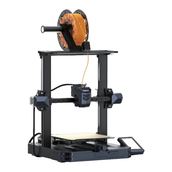
1. About the Printer Tool Kit Filament Detector Voltage Regulation Gear Z-Axis Motor Printing Platform Nozzle Kit Power Outlet Y-Axis Motor X-axis Kit Power Switch Coupling Light Stand USB Port X-axis Support Material Rack Assembly Display Screen X-Axis Motor... -
Page 6: Parts List
Head Screw M4*25 ×4 Head Screw M5*8 ×2 Washer M5*45 ×5 10-12 mm open-ended Cutting plier Nozzle cleaner Filament wrench Quick Installation Guide CR-10 SE After-Sales Service Card Scan the code to know more V1.2 E-mail: cs@creality.com V2.2 Nozzle cleaner USB flash disk... -
Page 7: Assembly Procedure
3. Assembly Procedure 3.1 Light Stand Installation ① Use two M5×8 screws to align and tighten the holes on the left and right of the ① light stand, and install the light stand on the gantry frame; ② Connect LED light cable; ③... -
Page 8: Gantry Frame Assembly Installation
3. Assembly Procedure 3.2 Gantry Frame Assembly Installation Place the gantry frame assembly in the base slot and lock it using four M5x45 screws aligned with the holes from the bottom. Bottom view... -
Page 9: Display Screen Component Installation
3. Assembly Procedure 3.3 Display Screen Component Installation ① Place the screen bracket on the side of the right profile, align it with the screw holes, ① and tighten it with three M4X25 screws; ② Align the pins on the back of the display screen with the large hole of the screen bracket and slide it down to lock it in place;... -
Page 10: Installation Of The Material Rack Assembly And Wire Clip
3. Assembly Procedure 3.4 Installation of the material rack assembly and wire clip ① Install the material rack and material barrel according to the diagram; ② Align the front slot of the installed material rack assembly with the front slot of the profile, and press it down firmly to secure the material rack assembly to the profile;... -
Page 11: Equipment Wiring
3. Assembly Procedure 3.5 Equipment Wiring ① Connect the filament detection line; ② Follow the label instructions to first insert the extruder cable into the cable Extruder adapter board clamp, then connect the extruder cable; X-axis motor ⑧ Connect the power cable Y-axis motor ③... -
Page 12: Pulley Tightness Adjustment
3. Assembly Procedure 3.6 Pulley Tightness Adjustment Before starting up, please check the tightness of the pulley. Z axis pulley adjustment: Gently dial the pulley to check whether it is idling or stuck. If this phenomenon occurs, use an open-end wrench to adjust the hexagonal eccentric isolation column to make it rotate smoothly. -
Page 13: About The Power-On Guide And User Interface
4. About the Power-on Guide and User Interface 4.1 Power-on guide The current interface is for reference only. Due to the continuous upgrading of functions, it shall be subject to the latest software/firmware UI published on the official website. - Page 14 4. About the Power-on Guide and User Interface Tips: The current interface is for reference only. Due to the continuous upgrading If any abnormalities occur during the self-check process, please of functions, it shall be subject to the refer to the FAQ to check for possible machine malfunctions; latest software/firmware UI published Alternatively, scan the QR code for “fault reporting"...
-
Page 15: About The User Interface
4. About the Power-on Guide and User Interface 4.2 About the User Interface Hotbed temperature Nozzle temperature The current interface is for reference only. Due to the continuous upgrading of functions, it shall be subject to the latest software/- Home firmware UI published on the official website. - Page 16 4. About the Power-on Guide and User Interface Local and USB flash disk model Print file preview files can be managed via the print file preview interface. Press and hold on the model to select multiple models and copy them to a USB flash disk *Up to a maximum of 3 models can be copied Model fan switch Print interface...
- Page 17 4.开机引导与设备界面简介 4. About the Power-on Guide and User Interface Machine system, network, and camera settings can be configured through the settings interface.(Camera is an optional feature) Customer Access the customer service interface to view FAQs, manuals, and log. Service The current interface is for reference only. Due to the continuous upgrading of functions, it shall be subject to the latest software/firmware UI published on the official website.
-
Page 18: First Printing
5. First Printing 5.1 Filament Loading ② Cut the front of the filament at 45° and break it off straight; PUSH ③ Gently press the extrusion clamp, insert the straightened filament into the hole, and observe filament flow from the ①... -
Page 19: Lan Printing
5. First Printing 5.2 LAN printing ※ Install Creality Print slicing software by opening the random data on the USB flash disk. ※ Log in to the official website to download for installation:https://www.crealitycloud.com/software-firmware/software?type=7 ① Select “Language" and “Server" ② Add the printer Open ③... - Page 20 5. First Printing ⑤ Set up material type ⑥ Set the print layer height and click on “Slice" ⑦ After slicing is done, click on “LAN printing" ⑧ Add equipment: can be added either by “Scan to add" or “Manually add". The current interface is for reference only.
- Page 21 5.首次打印 5. First Printing ⑧ Add a device: a. Add by scanning → Select a device ⑨ Device List ⑧ Add a device: b. Add a device by manually entering the IP address ⑩ Equipment printing information details Click “Settings" → “Network"...
-
Page 22: Usb Flash Disk Printing
5. First Printing 5.3 USB flash disk Printing ① Insert the USB flash ② Select the model from ③ Click on “Print" ④ Printing... disk into any USB port the USB flash disk The current interface is for reference only. Due to the Note: continuous upgrading of functions, it shall be subject to 1. -
Page 23: Functional Specification
6. Functional Specification Auto extrude The current interface is for reference only. Due to the continu- ous upgrading of functions, it shall be subject to the latest software/firmware UI published on the official website. Auto retract... -
Page 24: Equipment Maintenance
7. Equipment Maintenance 7.1 Platform plate removal and maintenance ① a. When printing is finished, wait for the platform plate to cool ② If there are residual filaments on the ③ If the first layer of the model is not before removing the printing platform with the model attached;... -
Page 25: Equipment Parameters
8. Equipment Parameters Equipment Parameters Model CR-10 SE Modeling Technolog Modeling Dimensions 220*220*265mm Leveling Method Auto-leveling Number of Nozzles 1pcs Extruder Diameter 0.4mm Slice Thickness 0.1-0.35mm Precision ±0.1mm Nozzle Temperature ≤300℃ Hotbed Temperature ≤110℃ Ambient Temperature 5℃~35℃ Filaments PLA/PETG/PET/TPU/PLA Wood/ABS/ASA/PA/PLA-CF... -
Page 26: Circuit Wiring
9. Circuit Wiring Limit switch 10P flexible flat cable X-Axis Motor (reserved) Flexible flat cable of pinboard Mainboard fan DC 24V Hotbed Hotbed thermistor Extruder Hotbed Display port communication communication (reserved) - Page 27 9. Circuit Wiring Extruder cable Height alignment sensor CR-Touch E-axis motor AI module Heating Thermistor Model fan Hotend fan pipes...
- Page 28 Due to the differences between different machine models, the actual objects and the images can differ. Please refer to the actual machine. The final explanation rights shall be reserved by Shenzhen Creality 3D Technology Co., Ltd. 18th Floor, JinXiuHongDu Building, Meilong Road, Xinniu Community, Minzhi Street, Longhua District, Shenzhen City, China.
Need help?
Do you have a question about the CR-10 SE and is the answer not in the manual?
Questions and answers
Після нічного друку (злитіла деталь)перестав бачить кінцеве положення по осі y
The Creality CR-10 SE may not be detecting the end position on the Y-axis after a night print due to a mechanical or sensor issue. Possible causes include:
1. Loose or Misaligned Belt – A previously reported issue involved the X-axis belt coming off, which suggests that the Y-axis belt might also be loose or misaligned, preventing proper movement detection.
2. Dirty or Faulty Endstop Sensor – If the Y-axis endstop sensor is dirty, damaged, or disconnected, the printer may not recognize when it reaches the end position.
3. Firmware or Calibration Issues – If the auto-leveling or movement calibration is incorrect, the printer may fail to detect the correct Y-axis limits.
4. Guide Rail or Screw Rod Issues – Lack of lubrication or debris in the Y-axis guide rail and screw rod could cause movement resistance, preventing the printer from reaching the endstop.
To resolve this, check and tighten the Y-axis belt, clean and inspect the endstop sensor, update or recalibrate firmware settings, and ensure the guide rails and screw rods are properly maintained.
This answer is automatically generated