
Subscribe to Our Youtube Channel
Related Manuals for Broadcom Brocade X6-8 Director


Summary of Contents for Broadcom Brocade X6-8 Director
- Page 1 Brocade X6-8 Director Hardware Installation Guide Hardware Installation Guide 23 April 2021 Broadcom 53-1004105-13 23 April 2021...
-
Page 2: Table Of Contents
Brocade X6-8 Director 53-1004105-13 Hardware Installation Guide Hardware Installation Guide Table of Contents Copyright Statement..........................8 Introduction............................9 About This Document..............................9 Supported Hardware................................ 9 Notes, Cautions, and Danger Notices......................... 10 ® Contacting Technical Support for Your Brocade Product..................10 Document Feedback..............................11 Device Overview..........................12... - Page 3 Brocade X6-8 Director 53-1004105-13 Hardware Installation Guide Hardware Installation Guide Items Required................................39 Providing Power to the Device.............................39 Connecting the Power Cord to AC Power Supplies....................40 Connecting to HVAC/HVDC Power Supplies......................40 Using HVAC/HVDC Power Cords........................43 Establishing a Serial Connection to the Device......................44 Configuring the IP Addresses............................
- Page 4 Brocade X6-8 Director 53-1004105-13 Hardware Installation Guide Hardware Installation Guide Interpreting Fan Assembly LEDs..........................83 Interpreting POST and Boot Results........................... 84 POST..................................84 Using Monitoring Commands............................85 chassisShow................................85 errDump and errShow...............................88 fanShow..................................88 haShow..................................88 historyShow................................89 psShow..................................90 sensorShow................................90 sfpShow..................................91 slotShow..................................
- Page 5 Brocade X6-8 Director 53-1004105-13 Hardware Installation Guide Hardware Installation Guide Replacing a Core Routing Blade..........................113 Preparing for Replacement............................. 114 Removing a Core Routing Blade..........................115 Installing a Core Routing Blade..........................116 Verifying Blade Operation............................118 Control Processor Blades.......................119 Control Processor Blade Overview..........................119 CPX6 Port Identification............................119...
- Page 6 Brocade X6-8 Director 53-1004105-13 Hardware Installation Guide Hardware Installation Guide HVAC/HVDC Power Supply Overview........................147 Power Supply Assembly Numbering......................... 148 Fan and Power Supply Airflow...........................149 Precautions Specific to Power Supply Assemblies....................150 Power Supply Assembly Fault Indicators......................... 150 Power Supply Assembly Task Guide.........................150 Time and Items Required............................
- Page 7 Brocade X6-8 Director 53-1004105-13 Hardware Installation Guide Hardware Installation Guide Chassis Fault Indicators..............................171 Time and Items Required............................171 Preparing for Replacement............................172 Recording Critical Device and SAN Information.....................172 Disconnecting from the Network and Fabric......................176 Removing Components from the Chassis........................ 176 Installing the Replacement Chassis...........................177...
-
Page 8: Copyright Statement
2018–2021 Broadcom. All Rights Reserved. Broadcom, the pulse logo, Brocade, and the stylized B logo are among the trademarks of Broadcom in the United States, the EU, and/or other countries. The term “Broadcom” refers to Broadcom Inc. and/or its subsidiaries. -
Page 9: Introduction
About This Document This hardware installation guide contains procedures and safety requirements for installing the Brocade X6-8 Director into a rack system or as a stand-alone device. Also provided are steps to initially configure the director for operation, verify and monitor operation, replace director field-replaceable units (FRUs), and install transceivers and cables. -
Page 10: Notes, Cautions, And Danger Notices
Safety labels are also attached directly to products to warn of these conditions or situations. ® Contacting Technical Support for Your Brocade Product If you purchased Brocade product support from a Broadcom OEM/solution provider, contact your OEM/solution provider for all your product support needs. Broadcom 53-1004105-13... -
Page 11: Document Feedback
OEM/solution providers are trained and certified by Broadcom to support Brocade products. • Broadcom provides backline support for issues that cannot be resolved by the OEM/solution provider. • Brocade Supplemental Support augments your existing OEM support contract, providing direct access to Brocade expertise. -
Page 12: Device Overview
Brocade X6-8 Director 53-1004105-13 Hardware Installation Guide Hardware Installation Guide Device Overview Product Features Key product features for this device include the following: • Redundant and hot-swappable SFP, SFP+, SFP28, QSFP+, and QSFP28 transceivers; port, extension, control processor (CP) and core routing (CR) blades; power supply assemblies, fan assemblies, and WWN cards that enable a high-availability platform and allow nondisruptive software upgrades for mission-critical SAN applications. -
Page 13: Port-Side View Of The Device
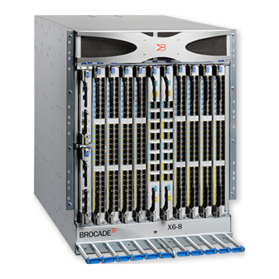
Port-Side View of the Device The following figure shows the port-side view of the Brocade X6-8 Director with installed blades identified. Note that the SX6 extension blade is not shown in the following figure, but would install in the same slots as the FC32-48 or FC32-64 port blades. - Page 14 Brocade X6-8 Director 53-1004105-13 Hardware Installation Guide Hardware Installation Guide Figure 1: Port Side of the Brocade X6-8 Director (Example Configuration) 1. Air vent 2. Core routing blades (CR32-8) 3. Port blades (FC32-48) 4. Cable management comb 5. Control processor blades (CPX6) – slot 1 (upper), slot 2 (lower) CAUTION Do not attempt to lift or support the chassis by the logo bezel attached over the port-side air vents.
-
Page 15: Port-Side Slot Numbering
Port-Side Slot Numbering The Brocade X6-8 Director contains 10 full-height slots and 2 half-height slots, for a total of 12 slots. Facing the port side of the device, the half-height slots are on the left, numbered 1 (top slot) and 2 (bottom slot). The remaining full-height slots are numbered 3 through 12, counting from left to right on the chassis. -
Page 16: Device Management Options
Brocade X6-8 Director 53-1004105-13 Hardware Installation Guide Hardware Installation Guide Figure 2: Nonport Side of the Director (Example Configuration) 1. WWN bezel (logo plate - WWN cards behind) 2. Power supply assembly 3. Fan assembly 4. 2AWG Panduit LCD2-14AF lug for building ground connection Depending on fans and power supplies that are installed, airflow can be from the port side to the nonport side of the chassis or from the nonport side to the port side of chassis. - Page 17 Brocade X6-8 Director 53-1004105-13 Hardware Installation Guide Hardware Installation Guide You can manage the device using any of the management options that are listed in the following table. Table 3: Management Options for the Device Management Tool Out-of-Band Support Reference Documents...
-
Page 18: Preparing For Installation
Brocade X6-8 Director 53-1004105-13 Hardware Installation Guide Hardware Installation Guide Preparing for Installation Safety Precautions When using this product, observe all danger, caution, and attention notices in this manual. The safety notices are accompanied by symbols that represent the severity of the safety condition. -
Page 19: Facility Requirements
Laser Radiation. Do Not View Directly with Optical Instruments. Class 1M Laser Products. DANGER Use only optical transceivers that are qualified by Broadcom and comply with the FDA Class 1 radiation performance requirements defined in 21 CFR Subchapter I, and with IEC 60825 and EN60825. Optical products that do not comply with these standards might emit light that is hazardous to the eyes. -
Page 20: Time And Items Required
Brocade X6-8 Director 53-1004105-13 Hardware Installation Guide Hardware Installation Guide Table 4: Facility Requirements Type Requirements Device specifications Ensure that the facility can accommodate the system, power, and environmental specifications for this device as outlined in the Technical Specifications. Electrical Ensure that there are dedicated electrical branch circuits with the following characteristics available: •... -
Page 21: Shipped Items
PNY Attache 3.0 4 USB 32GB Flash Drive • PNY Attache 3.0 4 USB 16GB Flash Drive These drives are not orderable from Broadcom but are widely available and can be purchased from other suppliers. Shipped Items When unpacking the device, follow procedures under Unpacking and Transporting the Device. -
Page 22: Quick Installation Checklists
Brocade X6-8 Director 53-1004105-13 Hardware Installation Guide Hardware Installation Guide The following items are packaged in a device shipping carton or separate carton: • Door (for EMI compliance) • Serial cable • ESD wrist strap • 4-GB USB drive •... - Page 23 Brocade X6-8 Director 53-1004105-13 Hardware Installation Guide Hardware Installation Guide Installation and Initial Configuration The initial setup includes mounting the device on a flat surface or in a rack and completing the configuration tasks necessary to bring the device online and verify the operation.
- Page 24 Brocade X6-8 Director 53-1004105-13 Hardware Installation Guide Hardware Installation Guide Task Task Details or Additional Information Completed • Check the LEDs to verify the operation of functional parts. See Monitoring Verify that the device operates Device. correctly. • The following commands can be useful to establish an operational baseline for the device.
-
Page 25: Mounting The Device
NOTE The preceding rack mount kits are supported for these devices on the publication date of this guide. For current support information, contact your Broadcom representative. Mounting Precautions The following precautions specifically apply to mounting the device. CAUTION Do not use the port cover tabs to lift the module. -
Page 26: Unpacking And Transporting The Device
Brocade X6-8 Director 53-1004105-13 Hardware Installation Guide Hardware Installation Guide NOTE You can connect the device to the building ground by connecting an appropriate 2 AWG wire from a grounded connection to the 2 AWG Panduit LCD2-14AF lug on the nonport-side of the device. -
Page 27: Installing The 14U Rack Mount Kit For Four-Post Racks (Xbr-Dcx-0120 And Xbr-Dcx-0152)
Brocade X6-8 Director 53-1004105-13 Hardware Installation Guide Hardware Installation Guide 8. Reinstall the cable management comb if you removed it. 9. Reinstall the chassis door. The door must be installed to meet EMI compliance. Installing the 14U Rack Mount Kit for Four-Post Racks (XBR-DCX-0120 and XBR-DCX-0152) Use the following instructions to install a modular device in a 48.3 cm (19-in.) EIA rack using the 14U Rack Mount Kit for... -
Page 28: Assembling The Rack Hardware
Brocade X6-8 Director 53-1004105-13 Hardware Installation Guide Hardware Installation Guide Description Installation Quantity 1/4-20 x 1/2 in. (1.27 cm) panhead Phillips screw with thread locker (torque must For rack rails with square holes be set to 92 cm-kg [80 in.-lb]) 3/8 in. - Page 29 Brocade X6-8 Director 53-1004105-13 Hardware Installation Guide Hardware Installation Guide NOTE If cables are to be routed down through the cable management comb, allow space below the brackets for cable management 1. Locate the shelf brackets in the device. 2. Locate and loosen the screws on the adjustable ends of the brackets to allow for adjustment to rack depth.
- Page 30 Brocade X6-8 Director 53-1004105-13 Hardware Installation Guide Hardware Installation Guide Figure 5: Nut and Screw Locations for Mounting the Device 1. 10-32 clip nuts (for round holes) 2. Rail 3. 10-32 retainer nut (for square holes) 4. Rail 5. Top screws in shelf bracket 6.
-
Page 31: Installing The Device In The Rack
Brocade X6-8 Director 53-1004105-13 Hardware Installation Guide Hardware Installation Guide NOTE Do not align the clip or retainer nuts with the top or bottom holes of the mounting bracket because the screw heads will interfere with the door. Installing the Device in the Rack Use the following procedure to install the device in the rack. -
Page 32: Installing The 14U Chassis Mid-Mount Rack Kit For Two-Post Racks (Xbr-Dcx-0121)
Brocade X6-8 Director 53-1004105-13 Hardware Installation Guide Hardware Installation Guide 6. Fasten the port side of the device to the rack rails. Use three 10-32 x 5/8 inch (1.58 cm) screws per rail. Tighten the screws to a torque of 37 cm-kg. (32 in.-lb). -
Page 33: Time And Items Required
Brocade X6-8 Director 53-1004105-13 Hardware Installation Guide Hardware Installation Guide Time and Items Required Allow approximately one hour to unpack and install a chassis in a rack. The following tools are required when installing the 14U Chassis Mid-Mount Rack Kit for Two-Post Racks. -
Page 34: Assembling The Rack Hardware
Brocade X6-8 Director 53-1004105-13 Hardware Installation Guide Hardware Installation Guide Assembling the Rack Hardware Perform the following steps to assemble the rack hardware. 1. Attach the rear tray (with or without an adapter, as required) to both rack rails. Orient the tray (see the following figure) and use nine screws (Item 5) for each rail. -
Page 35: Installing The Device In The Rack
Brocade X6-8 Director 53-1004105-13 Hardware Installation Guide Hardware Installation Guide Figure 10: Attaching the Front Tray to the Rack Rails 1. Tray, front, mid-mount, chassis 5. Screws Installing the Device in the Rack DANGER Use safe lifting practices when moving the product. - Page 36 Brocade X6-8 Director 53-1004105-13 Hardware Installation Guide Hardware Installation Guide 2. Orient the device (see the following figure) and use a hydraulic lift to raise it to the level of the trays. 3. If applicable, lock the wheels of the lift.
- Page 37 Brocade X6-8 Director 53-1004105-13 Hardware Installation Guide Hardware Installation Guide Figure 12: Attaching Trays to the Device 8. Reinstall the device door. Broadcom 53-1004105-13...
-
Page 38: Initial Setup And Verification
Brocade X6-8 Director 53-1004105-13 Hardware Installation Guide Hardware Installation Guide Initial Setup and Verification Configuration and Verification Task Guide Before connecting the device to the fabric, perform the following tasks to initially configure and set up the device, verify correct operation, and back up the configuration. -
Page 39: Items Required
Brocade X6-8 Director 53-1004105-13 Hardware Installation Guide Hardware Installation Guide Task Task Details or Additional Information Verify correct operation of director. Check LEDs on blades and FRUs, and use the following commands to verify operation: • errdump • fabricShow •... -
Page 40: Connecting The Power Cord To Ac Power Supplies
Brocade X6-8 Director 53-1004105-13 Hardware Installation Guide Hardware Installation Guide Connecting the Power Cord to AC Power Supplies Complete the following steps to connect the power cord from the facility AC power source to the device's AC power supply. Before connecting to power, be sure to observe all "Power Precautions" in Safety Precautions. - Page 41 Brocade X6-8 Director 53-1004105-13 Hardware Installation Guide Hardware Installation Guide NOTE Power is supplied to the device as soon as the first power supply is connected to a power source. CAUTION The maximum input voltage for connection to the HVAC/HVDC power supply should not exceed 305 VAC and 400 VDC .
- Page 42 Brocade X6-8 Director 53-1004105-13 Hardware Installation Guide Hardware Installation Guide 1. Connector latch 2. Power cable 7. Attach the cable restraint cover under the power cord connector using its two Torx head screws. NOTE This retainer cover protects the power cord from being accidentally unlatched and disconnected from the power supply.
-
Page 43: Using Hvac/Hvdc Power Cords
Brocade X6-8 Director 53-1004105-13 Hardware Installation Guide Hardware Installation Guide CAUTION Use a separate branch circuit for each power cord, which provides redundancy in case one of the circuits fails. 9. If connecting to a DC power source, use the following steps. -
Page 44: Establishing A Serial Connection To The Device
Brocade X6-8 Director 53-1004105-13 Hardware Installation Guide Hardware Installation Guide The Anderson Saf-D-Grid connector on the power supply end of the cord is keyed so that it only fits one way into the power supply. Note that the connector's latch should be positioned under the connector and will latch when the power cord connector is fully inserted into the power supply. - Page 45 Brocade X6-8 Director 53-1004105-13 Hardware Installation Guide Hardware Installation Guide 4. Access the device using a terminal emulator application (such as HyperTerminal in a Windows environment or TIP in a UNIX environment). 5. Disable any serial communication programs running on the workstation (such as synchronization programs).
-
Page 46: Configuring The Ip Addresses
Brocade X6-8 Director 53-1004105-13 Hardware Installation Guide Hardware Installation Guide Configuring the IP Addresses The device requires three IP addresses, which are configured using the ipaddrset command. IP addresses are required for both CP blades (CP0 and CP1) and for chassis management (shown as SWITCH under the ipaddrshow command) in the device. -
Page 47: Establishing An Ethernet Connection To The Device
Brocade X6-8 Director 53-1004105-13 Hardware Installation Guide Hardware Installation Guide 3. Set up the CP0 IP address by entering the ipaddrset -cp 0 command: swDir:admin> ipAddrSet -cp 0 Enter the required information at the prompts. Following is an example configuration for setting the CP0 IP address. -
Page 48: Setting The Domain Id
Brocade X6-8 Director 53-1004105-13 Hardware Installation Guide Hardware Installation Guide Setting the Domain ID Each device in the fabric must have a unique domain ID. The default domain ID is 1. If the device is not powered on until after it is connected to the fabric and the default domain ID is already in use, the domain ID for the new device is automatically reset to a unique value. -
Page 49: Setting The Time Zone
Brocade X6-8 Director 53-1004105-13 Hardware Installation Guide Hardware Installation Guide • mm is the month; valid values are 01 through 12. • dd is the date; valid values are 01 through 31. • HH is the hour; valid values are 00 through 23. -
Page 50: Synchronizing The Local Time With An External Source
Brocade X6-8 Director 53-1004105-13 Hardware Installation Guide Hardware Installation Guide Table 11: Example: tsTimeZone Command Parameter Selection for the U.S. Time Zones Local Time tsTimeZone Parameter (Difference from UTC) Atlantic Standard –4,0 Atlantic Daylight –3,0 Eastern Standard –5,0 Eastern Daylight –4,0... -
Page 51: Verifying Installed Licenses
Brocade X6-8 Director 53-1004105-13 Hardware Installation Guide Hardware Installation Guide NOTE Changing the name causes a domain address format RSCN to be issued. 1. Log onto the device using one of the following methods: • A serial console connection to the active CP blade. The active CP is indicated by an illuminated blue LED on the blade front panel. -
Page 52: Verifying Correct Operation
Besides saving configuration files to an FTP server or local file system, you can save them to a test validated USB device with the usbstorage command. NOTE Use a USB drive that has been test validated by Brocade, a Broadcom company: • SanDisk 32 CZ48 USB 3.0 Flash Drive (SDCZ48-032G-UAM46) •... -
Page 53: Powering Down The Chassis
Brocade X6-8 Director 53-1004105-13 Hardware Installation Guide Hardware Installation Guide These drives are not orderable from Broadcom but are widely available and can be purchased from other suppliers. 1. Log on to the device using one of the following methods: •... - Page 54 Brocade X6-8 Director 53-1004105-13 Hardware Installation Guide Hardware Installation Guide The system is going down for system halt NOW !! NOTE If you do not use the sysshutdown command and you sequence power off on power distribution units (PDU) with a few seconds between power-offs, be aware that a low-power condition will be detected and logged along with possible blade power-offs before shutdown.
- Page 55 Brocade X6-8 Director 53-1004105-13 Hardware Installation Guide Hardware Installation Guide 1. Power cable 2. Connector latch Broadcom 53-1004105-13...
-
Page 56: Installing Transceivers And Cables
Brocade X6-8 Director 53-1004105-13 Hardware Installation Guide Hardware Installation Guide Installing Transceivers and Cables Supported Transceivers and Cables For current information on qualified transceivers supported by this device, refer to the Brocade Transceiver Support Matrix and the resources on the Brocade Transceiver Module webpage. These resources include transceiver data sheets. -
Page 57: Port And Extension Blade Transceivers
2. SFP connectors DANGER Use only optical transceivers that are qualified by Broadcom and comply with the FDA Class 1 radiation performance requirements defined in 21 CFR Subchapter I, and with IEC 60825 and EN60825. Optical products that do not comply with these standards might emit light that is hazardous to the eyes. -
Page 58: Core Routing Blade Transceivers
Brocade X6-8 Director 53-1004105-13 Hardware Installation Guide Hardware Installation Guide Figure 16: Optical Transceiver with Bail Open 1. SFP+ bail The following illustration shows a 40GbE QSFP transceiver that uses a bail latching mechanism to release the transceiver from the blade port cage. A separate fiber optic cable connects to the transceiver. Some QSFP transceivers have an integrated pull tab that releases the transceiver from the port. -
Page 59: Time And Items Required
Brocade X6-8 Director 53-1004105-13 Hardware Installation Guide Hardware Installation Guide Figure 18: QSFP Transceiver with Separate Cable 1. Pull tab 2. QSFP cable 3. QSFP transceiver NOTE If the fiber optic cables are not connected to the transceivers, make sure that the rubber sealing gaskets are plugged into the transceivers. -
Page 60: Precautions Specific To Transceivers And Cables
All fiber-optic interfaces use Class 1 lasers. DANGER Use only optical transceivers that are qualified by Broadcom and comply with the FDA Class 1 radiation performance requirements defined in 21 CFR Subchapter I, and with IEC 60825 and EN60825. Optical products that do not comply with these standards might emit light that is hazardous to the eyes. -
Page 61: Installing An Sfp+ Transceiver
NOTE For current information on qualified transceivers supported by this device, refer to the Brocade Transceiver Support Matrix and the Brocade Transceiver Modules webpage on www.broadcom.com. The device supports only Brocade-qualified transceivers. If you use an unqualified transceiver, the switchshow command output shows the port in a Mod_Inv state. -
Page 62: Replacing An Sfp+ Transceiver
Brocade X6-8 Director 53-1004105-13 Hardware Installation Guide Hardware Installation Guide Figure 20: Installing an SFP+ Transceiver with a Bail Latch into a Blade Port 1. Bail Transceivers are keyed so that they can be inserted only with the correct orientation. If a transceiver does not slide in easily, ensure that it is correctly oriented. - Page 63 Brocade X6-8 Director 53-1004105-13 Hardware Installation Guide Hardware Installation Guide Figure 21: Replacing an SFP+ Optical Transceiver with a Pull Tab into a Blade Port 1. Pull tab 2. Transceiver • If the transceiver has a bail latch mechanism, unlatch from the port by pulling the bail (wire handle) away from its pivot point using your fingers or the hooked end of the transceiver extraction tool.
-
Page 64: Installing A Qsfp Transceiver
Brocade X6-8 Director 53-1004105-13 Hardware Installation Guide Hardware Installation Guide 4. Position a cable so that the key (the ridge on one side of the cable connector) is aligned with the slot in the transceiver. Insert the cable into the transceiver until the latching mechanism clicks. -
Page 65: Replacing A Qsfp Transceiver
Brocade X6-8 Director 53-1004105-13 Hardware Installation Guide Hardware Installation Guide 2. Position the cable so that the key (the ridge on one side of the cable connector) is aligned with the slot in the transceiver. Insert the cable into the transceiver until the latching mechanism clicks. -
Page 66: Verifying The Operation Of New Transceivers
Brocade X6-8 Director 53-1004105-13 Hardware Installation Guide Hardware Installation Guide 2. QSFP cable 3. QSFP transceiver The port's status LED initially blinks amber after installation, and then displays steady amber. 4. Position a cable so that the key (the ridge on one side of the cable connector) is aligned with the slot in the transceiver. -
Page 67: Monitoring The Device
Brocade X6-8 Director 53-1004105-13 Hardware Installation Guide Hardware Installation Guide Monitoring the Device Introduction This device is engineered for high reliability, high availability, and enhanced serviceability (RAS) and requires no routine operational steps or maintenance. This chapter provides information about determining the status of each component using LEDs and CLI commands. - Page 68 Brocade X6-8 Director 53-1004105-13 Hardware Installation Guide Hardware Installation Guide Figure 25: FC32-48 Port Blade LEDs 1. Blade power LED 2. Blade status LED 3. Status LED for right FC port 4. Status LED for left FC port The following table describes the port blade LED patterns and the recommended actions for those patterns.
- Page 69 Brocade X6-8 Director 53-1004105-13 Hardware Installation Guide Hardware Installation Guide Table 12: Port Blade LED Descriptions LED purpose Color Status Recommended Action Power Steady green Blade is operational. No action required. No light (LED is off) Blade is not powered on.
-
Page 70: Interpreting Fc32-64 Port Blade Leds
Brocade X6-8 Director 53-1004105-13 Hardware Installation Guide Hardware Installation Guide Interpreting FC32-64 Port Blade LEDs See the following figure and table to interpret the LED patterns for the FC32-64 blade. The LED patterns temporarily change during POST and other diagnostic tests. - Page 71 Brocade X6-8 Director 53-1004105-13 Hardware Installation Guide Hardware Installation Guide QSFPs only), the primary port LED (top LED) indicates the status of the single, unified QSFP port. For example, for a 40GbE QSFP in breakout mode, each of the four LEDs indicates the status of a 10GbE port. In nonbreakout mode, the primary (top) LED indicates the status of the unified 40GbE port.
-
Page 72: Interpreting Extension Blade Leds
Brocade X6-8 Director 53-1004105-13 Hardware Installation Guide Hardware Installation Guide LED Purpose Color Status Recommended Action Slow-flashing amber (on 1.28 Port is disabled due to diagnostic Reset the port from the workstation portDisable portDisable seconds, then off 1.28 seconds) tests or the... - Page 73 Brocade X6-8 Director 53-1004105-13 Hardware Installation Guide Hardware Installation Guide Figure 27: SX6 Extension Blade LEDs 1. Blade power LED 2. Blade status LED 3. Right 40GbE QSFP (port 0) status LED 4. Left 40GbE QSFP (port 1) status LED 5.
- Page 74 Brocade X6-8 Director 53-1004105-13 Hardware Installation Guide Hardware Installation Guide Table 14: Extension Blade LED Descriptions LED Purpose Color Status Recommended Action Power Steady green The blade is operational. No action is required. No light (LED is off) The blade is not powered on.
-
Page 75: Interpreting Core Routing Blade Leds
Brocade X6-8 Director 53-1004105-13 Hardware Installation Guide Hardware Installation Guide LED Purpose Color Status Recommended Action Slow-flashing amber (on 2 seconds, Port is disabled due to diagnostic Reset the port from the workstation portDisable portEnable then off 2 seconds) tests or to... - Page 76 Brocade X6-8 Director 53-1004105-13 Hardware Installation Guide Hardware Installation Guide Figure 28: CR32-8 Core Routing Blade LEDs 1. Blade power LED 2. Blade status LED 3. QSFP status LED for right QSFP port 4. QSFP status LED for left QSFP port...
-
Page 77: Interpreting Control Processor Blade Leds
Brocade X6-8 Director 53-1004105-13 Hardware Installation Guide Hardware Installation Guide Table 15: Core Routing Blade LED Descriptions LED Purpose Color Status Recommended Action Power Steady green The blade is on. No action is required. No light (LED is off) The blade is not on. - Page 78 Brocade X6-8 Director 53-1004105-13 Hardware Installation Guide Hardware Installation Guide Figure 29: Control Processor Blade (CPX6) 1. Blade power LED 2. Blade status LED 3. Chassis beacon LED 4. Active (blue) CP LED 5. 10/100/1000Mb/s Ethernet port (MGMT) link status LED 6.
-
Page 79: Interpreting Wwn Card Leds
Brocade X6-8 Director 53-1004105-13 Hardware Installation Guide Hardware Installation Guide LED Purpose Color Status Recommended Action Slow-flashing amber (on 2 seconds, CP blade is not seated correctly or Pull the blade out and reseat it. If then off 2 seconds) is faulty. -
Page 80: Interpreting Power Supply Leds
See the following information to interpret the LED patterns on the power supply. The LED patterns may temporarily change during POST and other diagnostic tests. The Brocade X6-8 Director can have up to four power supplies. Figure 31: AC Power Supply LED 1. - Page 81 Brocade X6-8 Director 53-1004105-13 Hardware Installation Guide Hardware Installation Guide Figure 32: HVAC/HVDC Power Supply LED 1. Power status LED The following tables describe the power supply LED patterns and the recommended actions for those patterns. In the unlikely event of a faulty power supply, the status LED will flash in a coded pattern to provide additional fault information.
- Page 82 Brocade X6-8 Director 53-1004105-13 Hardware Installation Guide Hardware Installation Guide LED Purpose Color Status Recommended Action Flashing on three times, 12V is out of range. Disconnect the power cable from the power and then off 5 seconds. supply, remove and reinsert the power supply, and then reconnect the power cable to restart.
-
Page 83: Interpreting Fan Assembly Leds
Interpreting Fan Assembly LEDs See the following figure and table to interpret the LED patterns on fan assemblies. The LED patterns may temporarily change during POST and other diagnostic tests. The Brocade X6-8 Director has three fan assemblies. Figure 33: Fan Assembly LEDs 1. -
Page 84: Interpreting Post And Boot Results
Brocade X6-8 Director 53-1004105-13 Hardware Installation Guide Hardware Installation Guide Table 21: Fan Assembly LED Descriptions LED Purpose Color Status Recommended Action Power No light (LED is off) The fan assembly does not have Ensure that the fan assembly is firmly power. -
Page 85: Using Monitoring Commands
Brocade X6-8 Director 53-1004105-13 Hardware Installation Guide Hardware Installation Guide POST includes the following steps: 1. Preliminary POST diagnostics are run. 2. The operating system is initialized. 3. Hardware is initialized. 4. Diagnostic tests are run on several functions, including circuitry, port functionality, ability to send and receive frames, all aspects of memory, parity, statistics counters, and serialization. - Page 86 Brocade X6-8 Director 53-1004105-13 Hardware Installation Guide Hardware Installation Guide Header Version: Power Consume Factor: -245W Power Usage: -152W Factory Part Num: 60-1003325-01 Factory Serial Num: DYJ0339L029 Manufacture: Day: Month: 11 Year: 2015 Update: Day: 15 Month: Year: 2016 Time Alive:...
- Page 87 Brocade X6-8 Director 53-1004105-13 Hardware Installation Guide Hardware Installation Guide Fan Direction: Non-portside Intake Header Version: Power Consume Factor: 2870w Factory Part Num: 23-0000161-01 Factory Serial Num: DUC2M35L092 Manufacture: Day: 25 Month: Year: 2015 Update: Day: 15 Month: Year: 2016...
-
Page 88: Errdump And Errshow
Brocade X6-8 Director 53-1004105-13 Hardware Installation Guide Hardware Installation Guide Chassis Factory Serial Num: BAF0289K00H errDump and errShow Use the errShow command to display device error log messages one at a time. Use the errDump command to display error log messages without any page breaks. The output of these commands are unique for each Control Processor (CP), so must be executed on each CP blade to obtain a complete record. -
Page 89: Historyshow
Brocade X6-8 Director 53-1004105-13 Hardware Installation Guide Hardware Installation Guide • Local CP state (slot number and CP ID), warm or cold, recovering or recovered. • Remote CP state (slot number and CP ID). • High Availability (enabled or disabled). -
Page 90: Psshow
Brocade X6-8 Director 53-1004105-13 Hardware Installation Guide Hardware Installation Guide Unit 1 Inserted at Mon Jun 13 13:59:14 2016 Factory Part Number: 60-1003194-02 Factory Serial Number: DZH0331L039 SW BLADE Slot 5 Inserted at Mon Jun 13 13:59:14 2016 Factory Part Number:... -
Page 91: Sfpshow
Brocade X6-8 Director 53-1004105-13 Hardware Installation Guide Hardware Installation Guide The following is an example of sensorShow output. chassisX6-8:admin> sensorshow sensor 1: (Temperature) is Ok, value is 30 C sensor 2: (Temperature) is Ok, value is 53 C sensor 3: (Temperature) is Ok, value is 31 C... -
Page 92: Supportsave
Brocade X6-8 Director 53-1004105-13 Hardware Installation Guide Hardware Installation Guide SW BLADE FC32-48 ENABLED SW BLADE FC32-48 ENABLED AP BLADE ENABLED SW BLADE FC32-48 DISABLED CORE BLADE CR32-8 ENABLED CORE BLADE CR32-8 ENABLED SW BLADE FC32-48 ENABLED UNKNOWN VACANT SW BLADE... -
Page 93: Switchshow
Brocade X6-8 Director 53-1004105-13 Hardware Installation Guide Hardware Installation Guide switchShow The switchShow command can be especially helpful in monitoring the health of the device. This command displays status, identification, and configuration information on the chassis and installed blades and ports. The following example shows output from this command. -
Page 94: Running Diagnostic Tests
Brocade X6-8 Director 53-1004105-13 Hardware Installation Guide Hardware Installation Guide • Sensor ID (an index number) • Slot number • Sensor index (when command issued with the --detail option) • Sensor state (OK or absent) • Temperature in both Centigrade and Fahrenheit The following is an example of tempShow output: chassisX6-8:admin>... -
Page 95: Port And Extension Blades
Brocade X6-8 Director 53-1004105-13 Hardware Installation Guide Hardware Installation Guide Port and Extension Blades FC32-48 Port Blade Overview The FC32-48 port blade contains 48 ports capable of Fibre Channel (FC) speeds up to 32G. Each port blade provides 48 backplane port connections to core routing blades. The port blade supports port-based in-flight encryption/decryption and compression/decompression. - Page 96 Brocade X6-8 Director 53-1004105-13 Hardware Installation Guide Hardware Installation Guide Figure 34: FC32-48 Blade Port Numbering 1. FC ports 0–23 (numbered bottom to top) 2. FC ports 24–47 (numbered bottom to top) Supported Transceivers and Cables for a list of qualified transceivers for blade ports.
-
Page 97: Fc32-64 Port Blade Overview
Brocade X6-8 Director 53-1004105-13 Hardware Installation Guide Hardware Installation Guide Port Number Port Group 16–23 24–31 32–39 40–47 Following are the requirements for forming trunk groups: • All ports in a trunk group must belong to the same port group. For example, to form an 8-port trunk select all eight ports from port group 0 or port group 1. -
Page 98: Fc32-64 Port Blade Numbering And Trunking
Brocade X6-8 Director 53-1004105-13 Hardware Installation Guide Hardware Installation Guide installed in a port to configure FCoE operation for that port. Supported Ethernet transceivers include 40GbE, 4x10GbE, and 4x25GbE QSFP+ transceivers. For more details on FCoE, Flexport, and breakout mode features and commands, refer to the Brocade Fabric OS Administration Guide and Brocade Fabric OS Command Reference Manual. -
Page 99: Extension Blade Overview
Brocade X6-8 Director 53-1004105-13 Hardware Installation Guide Hardware Installation Guide The following table defines the eight-port Fibre Channel port groups for configuring trunk groups or "trunks." Color coding on the physical blade identifies the port groups. On the blade, ports belonging to the same port group are indicated with the same color border beneath the port on the blade label. -
Page 100: Extension Features
Brocade X6-8 Director 53-1004105-13 Hardware Installation Guide Hardware Installation Guide operate at 10GbE or 1GbE fixed speeds with appropriate 10G or 1G transceivers installed. The 40GbE QSFP ports operate at 40GbE fixed speed. Extension blades have the following LED indicators: •... -
Page 101: Sx6 Blade Port Numbering And Trunking
Brocade X6-8 Director 53-1004105-13 Hardware Installation Guide Hardware Installation Guide – A maximum of 8 circuits can be configured per tunnel. – A maximum of 20 tunnels (VE_Ports) can be configured for all GbE ports. – The maximum committed rate of a single circuit is 10G, whether configured on a 10GbE or 40GbE port. -
Page 102: Blade-Specific Precautions
Brocade X6-8 Director 53-1004105-13 Hardware Installation Guide Hardware Installation Guide 5. FC ports 0, 1, 2, 3, 8, 9, 10, 11 (bottom to top) 6. FC ports 4, 5. 6, 7, 12, 13, 14, 15 (bottom to top) Following are the eight-port Fibre Channel port groups for configuring trunk groups or "trunks": •... -
Page 103: Time And Items Required For Removal And Installation
Brocade X6-8 Director 53-1004105-13 Hardware Installation Guide Hardware Installation Guide • The status LED on the blade is lit steady amber, or the power LED is not illuminated. • The slotShow command does not show that the blade is enabled. - Page 104 Brocade X6-8 Director 53-1004105-13 Hardware Installation Guide Hardware Installation Guide • Before removing any cables from a blade, note the cable order (identify each cable by its physical port). • It is a good practice to create a table of cable-to-port mapping for reference.
- Page 105 Brocade X6-8 Director 53-1004105-13 Hardware Installation Guide Hardware Installation Guide 12. Continue pulling the blade from the slot by the blade edges. As you slide out the blade, place one hand under it for support. Do not support the blade by the injector handles after removal.
-
Page 106: Installing A Blade
Brocade X6-8 Director 53-1004105-13 Hardware Installation Guide Hardware Installation Guide Installing a Blade Complete this procedure to install a port or extension blade. These steps apply to all port and extension blades installed in the device. 1. If a protective sleeve is covering the blade connectors, remove the sleeve. -
Page 107: Verifying Blade Operation
Brocade X6-8 Director 53-1004105-13 Hardware Installation Guide Hardware Installation Guide 5. Observe the blade power and status LEDs and verify the following: a) Verify that the status LED on the blade shows amber until POST completes for the blade. The status LED should then display green to indicate that the blade has power. -
Page 108: Core Routing Blades
Brocade X6-8 Director 53-1004105-13 Hardware Installation Guide Hardware Installation Guide Core Routing Blades Core Routing Blade Overview Two CR32-8 core routing blades are installed in device slots 7 and 8. Core routing blades contain ASICs that allow switching between up to eight port blades. Core routing blades connect to port blades through Fibre Channel backplane ports. - Page 109 Brocade X6-8 Director 53-1004105-13 Hardware Installation Guide Hardware Installation Guide Figure 38: CR32-8 Core Routing Blade Port Numbering 1. Map showing ports 6, 7, 14, 15 2. Map showing ports 4, 5, 12, 13 3. QSFP ports 8-15 (bottom to top) 4.
-
Page 110: Icl Trunking Groups
QSFPs within a trunk group on a core blade in another device. Each CR32-8 blade on the Brocade X6-8 Director has four ICL trunking groups consisting of the following QSFP ports. •... - Page 111 Brocade X6-8 Director 53-1004105-13 Hardware Installation Guide Hardware Installation Guide Following are the maximum numbers of directors that you can connect using 4x32G quad SFP (QSFP) inter-chassis links (ICLs): • Up to nine X6 (Gen 6) directors can be connected in a full-mesh topology.
-
Page 112: Blade-Specific Precautions
This document describes how to remove and replace a core routing blade. Observe the following precautions when replacing these blades: • The CR32-8 core routing blade is compatible only with the Brocade X6-8 Director. • Wear an appropriately grounded ESD wrist strap when handling and installing blades and cards. Follow electrostatic discharge (ESD) precautions. -
Page 113: Faulty Core Routing Blade Indicators
Brocade X6-8 Director 53-1004105-13 Hardware Installation Guide Hardware Installation Guide CAUTION If you do not install a module or a power supply in a slot, you must keep the slot filler panel in place. If you run the chassis with an uncovered slot, the system will overheat. -
Page 114: Preparing For Replacement
Brocade X6-8 Director 53-1004105-13 Hardware Installation Guide Hardware Installation Guide • Preparing for Replacement. Use these procedures to ensure that traffic is not disrupted through existing ICL connections when you are replacing a core routing blade. If ICLs are not connected to the blade or traffic through ICL... -
Page 115: Removing A Core Routing Blade
Brocade X6-8 Director 53-1004105-13 Hardware Installation Guide Hardware Installation Guide Removing a Core Routing Blade Perform the following procedures to remove one core routing blade at a time with chassis power on. You must replace the blade and ensure its operation before removing the other core routing blade. Removing both blades will power down the chassis. -
Page 116: Installing A Core Routing Blade
Brocade X6-8 Director 53-1004105-13 Hardware Installation Guide Hardware Installation Guide 12. Continue pulling the blade from the slot by the blade edges. As you slide out the blade, place one hand under it for support. Do not support the blade by the injector handles after removal. - Page 117 Brocade X6-8 Director 53-1004105-13 Hardware Installation Guide Hardware Installation Guide NOTE The device continues to operate while a core routing blade is installed. 1. If a protective sleeve is covering the blade connectors, remove the sleeve. 2. Rotate the ejector handles away from the center of the blade completely—approximately 45 degrees. Do not support the blade using the ejector handles.
-
Page 118: Verifying Blade Operation
Brocade X6-8 Director 53-1004105-13 Hardware Installation Guide Hardware Installation Guide b) Verify that the power LED on the port blade is displaying a steady green light to indicate that the blade has power. If it does not turn on, ensure that the blade is firmly seated and the ejector captive screws are tightened. -
Page 119: Control Processor Blades
Control Processor Blade Overview The CPX6 control processor blades are half the slot height of other Brocade X6-8 Director blades. Two CPX6 control processor blades are stacked vertically in the half slots on the left side of the chassis to provide CP redundancy. CP0 is installed in slot 1, while CP1 is installed in slot 2. -
Page 120: Blade-Specific Precautions
Brocade X6-8 Director 53-1004105-13 Hardware Installation Guide Hardware Installation Guide Figure 42: CPX6 Blade Port Identification 1. 10GBASE-T RJ-45 Ethernet Port (reserved for future use) 2. USB 4 Port for Firmware Download and Logs 3. Serial Console RJ-45 port 4. 10/100/1000BASE-T RJ-45 Ethernet Port for Chassis Management and Configuration 5. -
Page 121: Blade Fault Indicators
Brocade X6-8 Director 53-1004105-13 Hardware Installation Guide Hardware Installation Guide CAUTION Static electricity can damage the chassis and other electronic devices. To avoid damage, keep static-sensitive devices in their static-protective packages until you are ready to install them. CAUTION Before plugging a cable into any port, be sure to discharge the voltage stored on the cable by touching the electrical contacts to ground surface. -
Page 122: Time And Items Required
Brocade X6-8 Director 53-1004105-13 Hardware Installation Guide Hardware Installation Guide If you need to download firmware to update the blades, follow the steps in one of the following sections: • Downloading Firmware from an FTP Server • Downloading Firmware from a USB Device 5. -
Page 123: Replacing A Control Processor Blade
Brocade X6-8 Director 53-1004105-13 Hardware Installation Guide Hardware Installation Guide 2. Connect to the device and log on as admin using a serial console connection. 3. Enter haShow to determine which CP blade is active. Gen7-4:admin> hashow Local CP (Slot 1, CP0): Active, Warm Recovered... -
Page 124: Replacing A Cp Blade: Hot-Swap Procedure
Brocade X6-8 Director 53-1004105-13 Hardware Installation Guide Hardware Installation Guide Replacing a CP Blade: Hot-Swap Procedure Use this procedure to replace CP blades, one at a time, while the device power is on. The device continues to operate while replacing a blade if the redundant blade is active and failover does not occur. You can prevent failover by entering the haDisable command. -
Page 125: Installing A Blade
Brocade X6-8 Director 53-1004105-13 Hardware Installation Guide Hardware Installation Guide 9. Continue pulling the blade from the slot by the blade edges. As you slide out the blade, place one hand under it for support. Do not support the blade by the injector handles after removal. -
Page 126: Verifying And Synchronizing Firmware On Blades
Brocade X6-8 Director 53-1004105-13 Hardware Installation Guide Hardware Installation Guide Complete the following steps to install a CP blade. 1. If a protective sleeve is covering the blade connectors, remove the sleeve. 2. Rotate the ejector handles away from center of blade completely - approximately 45 degrees. Do not support the blade using ejector handles. - Page 127 Brocade X6-8 Director 53-1004105-13 Hardware Installation Guide Hardware Installation Guide 2. Log on to each CP blade and enter the haShow command to display the CP status. Verify the CP state, status, health, and that the HA state is synchronized. Remedy any issues before proceeding. For more information on haShow output, refer to the Brocade Fabric OS Command Reference Manual.
- Page 128 Brocade X6-8 Director 53-1004105-13 Hardware Installation Guide Hardware Installation Guide Slot 1 (CP0, active): Firmwaredownload command has completed successfully. Use firmwareshow to verify the firmware versions. 4. On the standby CP blade (the blade for which you just changed the firmware level), run reboot . The reboot of the standby CP will initiate a firmwarecommit to the secondary partition and log you out.
- Page 129 Brocade X6-8 Director 53-1004105-13 Hardware Installation Guide Hardware Installation Guide Complete the following steps to download the firmware from a USB device to the replacement blade. 1. Insert the USB device into the active CP blade. 2. Attach a serial cable from the PC to the active CP blade.
-
Page 130: Replacing A Cp Blade: Cold-Swap Procedure
Brocade X6-8 Director 53-1004105-13 Hardware Installation Guide Hardware Installation Guide 8. Log back on to the standby CP blade and enter firmwareDownloadStatus on the standby CP blade to validate a successful commit. This may take 10 minutes. 9. If you are upgrading through several levels of the Fabric OS, repeat Step 5 through Step 8 as often as necessary based on the path outlined in the preceding table. -
Page 131: Installing A Blade
Brocade X6-8 Director 53-1004105-13 Hardware Installation Guide Hardware Installation Guide 8. Continue pulling the blade from the slot by the blade edges. As you slide out the blade, place one hand under it for support. Do not support the blade by the injector handles after removal. -
Page 132: Completing The Replacement
Brocade X6-8 Director 53-1004105-13 Hardware Installation Guide Hardware Installation Guide c) Continue pushing with your thumbs or fingers until the ejectors move in towards the blade slightly, indicating that the connectors are engaged. d) Simultaneously push both ejector handles in towards the blade center with even pressure until the blade completely seats in the slot. -
Page 133: Verifying Blade Operation
Brocade X6-8 Director 53-1004105-13 Hardware Installation Guide Hardware Installation Guide Remote CP (Slot 1, CP0) : Standby, Healthy HA Enabled, Heartbeat Up, HA State Synchronized 3. Enter firmwareShow to verify that the firmware version has been updated and that the versions are the same on the two CP blades. - Page 134 Brocade X6-8 Director 53-1004105-13 Hardware Installation Guide Hardware Installation Guide Using Monitoring Commands and the Brocade Fabric OS Command Reference Manual for output examples and additional information on Fabric OS commands. For more information about error messages, refer to the Brocade Fabric OS Message Reference Manual.
-
Page 135: Wwn Cards
Brocade X6-8 Director 53-1004105-13 Hardware Installation Guide Hardware Installation Guide WWN Cards WWN Card Overview Two WWN cards are located behind the WWN bezel (logo plate) between the power supplies on the nonport side of the device. WWN 1 is located on the left side, and WWN 2 is located on the right side. The WWN cards store critical configuration data, such as WWN, IP addresses, part and serial numbers, and license IDs for the device. -
Page 136: Precautions Specific To Wwn Cards
Brocade X6-8 Director 53-1004105-13 Hardware Installation Guide Hardware Installation Guide Figure 45: WWN Card Location and Numbering 1. WWN card 1 2. WWN card 2 3. WWN card bezel Precautions Specific to WWN Cards Observe the following precautions for these cards: •... - Page 137 Brocade X6-8 Director 53-1004105-13 Hardware Installation Guide Hardware Installation Guide • RASlog messages may occur during periodic WWN card audit routines, alerting you of data or license mismatches between WWN cards and other errors. Some of these messages may direct you to contact technical support or to run the wwnrecover command.
-
Page 138: Wwn Card Replacement Task Guide
Brocade X6-8 Director 53-1004105-13 Hardware Installation Guide Hardware Installation Guide WWN Card Replacement Task Guide This section contains a guide to more complete, detailed steps in this section for installing or replacing WWN cards when the device is running (hot-swap) or must be powered off (cold-swap). References are provided to more detailed WWN removal and installation steps for further information. - Page 139 Brocade X6-8 Director 53-1004105-13 Hardware Installation Guide Hardware Installation Guide If a data mismatch is detected during the audit, messages in the RASlog will provide a summary of all errors detected and prompt you through a data recovery process. The data recovery mechanism may vary depending on the error encountered and the data being compared.
-
Page 140: Preparing For Replacement
Brocade X6-8 Director 53-1004105-13 Hardware Installation Guide Hardware Installation Guide Preparing for Replacement If the WWN cards require replacement, complete the following steps. Follow electrostatic discharge (ESD) precautions. 1. Open a Telnet session to the device and log on to the active CP blade as admin. The default password is "password". -
Page 141: Hot-Swap Replacement
Brocade X6-8 Director 53-1004105-13 Hardware Installation Guide Hardware Installation Guide 10:00:00:05:1e:95:b1:00 0x00 0x200a00 Type number: SLKWRM Model number: Manufacturer: Plant of Manufacture: CA Sequence Number: 0AFX2533G001 tag: b6ff 5. Contact Brocade Technical Support for the replacement WWN cards. Brocade Support will provide replacements. Brocade Support requires the supportSave data that was captured in the previous step so that the replacement cards can be programmed before shipping to your site. -
Page 142: Cold-Swap Replacement
Brocade X6-8 Director 53-1004105-13 Hardware Installation Guide Hardware Installation Guide 9. Verify the new card settings by running the following commands and comparing the output with the original supportsave data: • chassisname • chassisshow (look at the WWN and chassis information at the bottom) •... -
Page 143: Removing The Wwn Card And Bezel
Brocade X6-8 Director 53-1004105-13 Hardware Installation Guide Hardware Installation Guide 5. Install replacement WWN card assemblies into the empty slot using the following steps: a) Holding the card assembly by its edges with both hands along its length, slide it into the device slot. -
Page 144: Configuring The Airflow Direction On Wwn Cards
Brocade X6-8 Director 53-1004105-13 Hardware Installation Guide Hardware Installation Guide NOTE Unless the device is powered down and not operational, do not perform these steps without first performing procedures under either Hot-Swap Replacement Cold-Swap Replacement. 1. Remove the two screws from the WWN bezel on the back of the device using a Phillips screwdriver. Pull the bezel away from the chassis and set it aside. -
Page 145: Verifying Wwn Card Operation
Brocade X6-8 Director 53-1004105-13 Hardware Installation Guide Hardware Installation Guide direction on the WWN cards, provided all installed fan and power supply assemblies have the same airflow direction. RASLOG messages such as the following will occur during this automatic configuration: ...[HIL-1630], 449, SLOT 1 CHASSIS, INFO, chassis1, Auto-configuring... -
Page 146: Power Supply Assemblies
7. Captive screw The Brocade X6-8 Director can have three or four power supplies installed, depending on the quantity ordered. The use of the high-voltage line (200 to 240 VAC) is highly recommended because of better power conversion efficiency. See "Power Supply Requirements"... -
Page 147: Hvac/Hvdc Power Supply Overview
Brocade X6-8 Director 53-1004105-13 Hardware Installation Guide Hardware Installation Guide HVAC/HVDC Power Supply Overview The Brocade X6 chassis supports a dual-function high-voltage AC, high-voltage DC (HVAC/HVDC) power supply assembly. This power supply converts AC or DC input to the required DC output power required for device operation. -
Page 148: Power Supply Assembly Numbering
Hardware Installation Guide • The Brocade X6-8 Director can have three or four power supplies installed, depending on the quantity ordered. The use of the high-voltage line (200 to 277 VAC) is advised because of better power conversion efficiency. See "Power Supply Requirements"... -
Page 149: Fan And Power Supply Airflow
Brocade X6-8 Director 53-1004105-13 Hardware Installation Guide Hardware Installation Guide Fan and Power Supply Airflow All fans and power supply FRUs installed in this device must have either NPI (nonport-side intake) or NPE (nonport- side exhaust) airflow. You must order a replacement FRU with the same part number (P/N) as the FRU being replaced to provide the same airflow. -
Page 150: Precautions Specific To Power Supply Assemblies
Brocade X6-8 Director 53-1004105-13 Hardware Installation Guide Hardware Installation Guide NOTE Ensure that the captive screws securing the fan and power supply assemblies are tightened. If they are not tightened, the air pressure inside the chassis may unseat these FRUs from chassis connectors. -
Page 151: Time And Items Required
Brocade X6-8 Director 53-1004105-13 Hardware Installation Guide Hardware Installation Guide NOTE Depending on the blade configuration of the chassis and the number of power supplies installed, the chassis may be able to continue operating while you replace a power supply. See... -
Page 152: Removing A Power Supply
Brocade X6-8 Director 53-1004105-13 Hardware Installation Guide Hardware Installation Guide Removing a Power Supply To remove a power supply, complete the following steps: 1. Before removing a power supply assembly, verify whether you can remove the power supply and leave the chassis operating (hot-swap replacement) or whether you must power down the chassis (cold-swap replacement). - Page 153 Brocade X6-8 Director 53-1004105-13 Hardware Installation Guide Hardware Installation Guide 4. Grasp the handle and pull, sliding the power supply from the chassis and supporting the power supply from beneath as you remove it. Figure 51: Removing and Installing Power Supply Assembly 5.
-
Page 154: Installing A Power Supply
Brocade X6-8 Director 53-1004105-13 Hardware Installation Guide Hardware Installation Guide Installing a Power Supply To install a power supply, complete the following steps: 1. If a filler panel is installed over the slot where you are installing the power supply, remove the panel by loosening the captive screw that is located on the right side of the panel. - Page 155 Brocade X6-8 Director 53-1004105-13 Hardware Installation Guide Hardware Installation Guide Using Monitoring Commands and the Brocade Fabric OS Command Reference Manual for output examples and additional information on Fabric OS commands. For more information about error messages, refer to the Brocade Fabric OS Message Reference Manual.
-
Page 156: Fan Assemblies
Brocade X6-8 Director 53-1004105-13 Hardware Installation Guide Hardware Installation Guide Fan Assemblies Fan Assembly Overview The following list shows important details that you should note about fan assemblies: • Three fan assemblies are installed in the chassis, containing two fans each, for a total of six fans. -
Page 157: Fan And Power Supply Airflow
Brocade X6-8 Director 53-1004105-13 Hardware Installation Guide Hardware Installation Guide Figure 52: Fan Assembly 1. Power LED 2. Captive screw 3. Status LED 4. Airflow label 5. Air vent 6. Handle 7. Captive screw Fan and Power Supply Airflow All fans and power supply FRUs installed in this device must have either NPI (nonport-side intake) or NPE (nonport- side exhaust) airflow. -
Page 158: Fan Assembly Numbering
Brocade X6-8 Director 53-1004105-13 Hardware Installation Guide Hardware Installation Guide NOTE If airflow direction for a power supply assembly does not match the chassis airflow direction as stored on WWN cards, the power supply will have a "fault" status. However, the LED operation for the power supply will not indicate a fault. -
Page 159: Precautions Specific To Fan Assemblies
Brocade X6-8 Director 53-1004105-13 Hardware Installation Guide Hardware Installation Guide Figure 54: Fan Assembly Numbering 1. Fan assembly 1 2. Fan assembly 2 3. Fan assembly 3 Precautions Specific to Fan Assemblies Observe the following precautions when replacing fan assemblies. -
Page 160: Fan Assembly Task Guide
Brocade X6-8 Director 53-1004105-13 Hardware Installation Guide Hardware Installation Guide – Steady amber – fan assembly has a failure (full or partial). – Slow-flashing amber (on 2 seconds, then off 2 seconds) – fan assembly is not seated correctly or is faulty. -
Page 161: Time And Items Required
Brocade X6-8 Director 53-1004105-13 Hardware Installation Guide Hardware Installation Guide Time and Items Required The replacement procedure for each fan assembly takes less than 5 minutes. The following items are required for the blower assembly replacement: • Replacement fan assembly •... -
Page 162: Installing A Fan Assembly
Brocade X6-8 Director 53-1004105-13 Hardware Installation Guide Hardware Installation Guide 5. If you are leaving power on for replacement (hot-swap), be sure to replace the fan assembly as soon as possible. This completes the procedure for removing a fan assembly. -
Page 163: Blade Filler Panels
Brocade X6-8 Director 53-1004105-13 Hardware Installation Guide Hardware Installation Guide Blade Filler Panels Blade Filler Panel Removal and Replacement When installing a blade into the device, you may need to first remove a blade filler panel. Be sure to keep all filler panels in a safe place in case you need to remove a blade for an indefinite period of time. - Page 164 Brocade X6-8 Director 53-1004105-13 Hardware Installation Guide Hardware Installation Guide Figure 56: Removing and Installing the Blade Filler Panel on an X6-8 Director 1. Latch pull tab 2. Latch release 4. Reinstall the chassis door. The door must be installed to meet EMI compliance.
-
Page 165: Cable Management Comb
Cable Management Comb Cable Management Comb Overview Use the cable management comb to organize and route cables attached to blade ports. The Brocade X6-8 Director can continue to operate while removing or installing the cable management comb. Time and Items Required for Removal and Installation The replacement procedure for the cable management comb takes less than five minutes. -
Page 166: Removing The Cable Management Comb
Brocade X6-8 Director 53-1004105-13 Hardware Installation Guide Hardware Installation Guide Removing the Cable Management Comb Complete the following steps to remove the cable management comb: 1. Remove the cables from the cable management comb and rearrange the cables around the comb. -
Page 167: Chassis Door
Brocade X6-8 Director 53-1004105-13 Hardware Installation Guide Hardware Installation Guide Chassis Door Chassis Door Overview The chassis door must be installed to ensure that the device meets EMI and other regulatory certifications. A receiving hole is located on each corner on the back side of the door. Each hole snaps into a ball stud located on a matching corner of the chassis. -
Page 168: Installing A Chassis Door
Brocade X6-8 Director 53-1004105-13 Hardware Installation Guide Hardware Installation Guide Installing a Chassis Door Complete the following steps to install the door on the port side of the chassis. Before installing the door, use step 1 to remove the logo bezel if it is attached over the air vents at the top of the chassis. If the bezel has been removed, skip to step 2 to install the door. - Page 169 Brocade X6-8 Director 53-1004105-13 Hardware Installation Guide Hardware Installation Guide 2. Align the ball stud attachment holes located vertically on each side of the rear of door with the ball studs on each chassis mounting ear. Push door onto chassis to snap onto the studs.
-
Page 170: Replacing The Chassis
Brocade X6-8 Director 53-1004105-13 Hardware Installation Guide Hardware Installation Guide Replacing the Chassis Chassis Replacement Overview Before replacing the chassis, you will need to remove all the blades and the FRUs, except the WWN cards, from the existing chassis. You will reinstall these in the replacement chassis. -
Page 171: Chassis Replacement Task Guide
Brocade X6-8 Director 53-1004105-13 Hardware Installation Guide Hardware Installation Guide Chassis Replacement Task Guide The following are the basic tasks for removing and replacing the chassis with its backplane: NOTE The device must be removed from the fabric and powered off to perform these tasks. Contact your support provider if you have any questions about whether the chassis requires replacement. -
Page 172: Preparing For Replacement
Brocade X6-8 Director 53-1004105-13 Hardware Installation Guide Hardware Installation Guide • Electrostatic discharge (ESD) grounding strap. • ESD grounding pads for protecting all blades and WWN cards. • Serial cable and workstation computer with a terminal emulator application (such as HyperTerminal for Windows systems or TIP for Solaris systems), required only if serial console session used. - Page 173 Brocade X6-8 Director 53-1004105-13 Hardware Installation Guide Hardware Installation Guide Checked? Data Notes ANbefor.txt Location of file nsshow Notes regarding output nsallshow Notes regarding output switchshow Notes regarding output fabricshow Notes regarding output license --show licenseshow Output from the command License keys and other licensing data for licensed products enabled on the device.
- Page 174 Brocade X6-8 Director 53-1004105-13 Hardware Installation Guide Hardware Installation Guide Ethernet IP Address: 192.0.2.2 Ethernet Subnetmask: 255.255.255.0 Host Name: cp0 Gateway IP Address: 192.0.2.6 Ethernet IP Address: 192.0.2.3 Ethernet Subnetmask: 255.255.240.0 Host Name: cp1 Gateway IP Address: 192.0.2.6 Backplane IP address of CP0 : 192.0.2.4 Backplane IP address of CP1 : 192.0.2.5...
- Page 175 Brocade X6-8 Director 53-1004105-13 Hardware Installation Guide Hardware Installation Guide <output truncated> switch:admin> fabricshow Switch ID Worldwide Name Enet IP Addr FC IP Addr Name <output truncated> switch:admin> 7. Enter license --show , and then copy the command output into a text file named licenseshow.txt .
-
Page 176: Disconnecting From The Network And Fabric
Brocade X6-8 Director 53-1004105-13 Hardware Installation Guide Hardware Installation Guide BootProm: 4.0.11-sb (output truncated) 9. Record the cable connections between the chassis and the target device and ports. 10. Run supportSave on the active CP blade. 11. Record the information that the supportSave command returns. -
Page 177: Installing The Replacement Chassis
Brocade X6-8 Director 53-1004105-13 Hardware Installation Guide Hardware Installation Guide When removing components, wear a wrist grounding strap connected to a bench ground. DANGER For safety reasons, the ESD wrist strap should contain a series 1 megaohm resistor. 1. Remove the chassis door (Removing a Chassis Door) if not already removed. -
Page 178: Installing Components Into The Chassis
Brocade X6-8 Director 53-1004105-13 Hardware Installation Guide Hardware Installation Guide Installing Components into the Chassis Follow electrostatic discharge (ESD) precautions when installing new components. Wear a wrist grounding strap connected to a chassis ground (if the device is plugged in) or a bench ground. -
Page 179: Downloading The Configuration
Brocade X6-8 Director 53-1004105-13 Hardware Installation Guide Hardware Installation Guide If the chassisShow command or RASlog messages indicate a mismatch between the system airflow direction and the airflow direction of the fan in the power supply or fan assemblies, see Configuring the Airflow Direction on WWN Cards instructions on configuring correct airflow direction on WWN cards. -
Page 180: Verifying Correct Operation Of The System
Brocade X6-8 Director 53-1004105-13 Hardware Installation Guide Hardware Installation Guide NOTE Once an Ethernet connection is established, the device can be accessed by remote connection using any of the available management tools, such as Telnet or Web Tools. 2. Reconnect the transceivers and cables to the port blades. - Page 181 Brocade X6-8 Director 53-1004105-13 Hardware Installation Guide Hardware Installation Guide 3. Enter the slotShow -m command and verify that all the installed cards are detected and that their status is operational (enabled). switch:admin> slotShow -m Slot Blade Type Model Name...
-
Page 182: Verifying Correct Configuration Of The Fabric
Brocade X6-8 Director 53-1004105-13 Hardware Installation Guide Hardware Installation Guide switch:admin> ipaddrshow SWITCH Ethernet IP Address: 192.0.2.0 Ethernet Subnetmask: 255.255.255.0 Fibre Channel IP Address: 1.2.3.4 Fibre Channel Subnetmask: 255.255.255.0 Ethernet IP Address: 192.0.2.2 Ethernet Subnetmask: 255.255.255.0 HostName : cp0 Gateway Address: 192.0.2.6 Ethernet IP Address: 192.0.2.3... - Page 183 Brocade X6-8 Director 53-1004105-13 Hardware Installation Guide Hardware Installation Guide <output truncated> 2. Determine any differences between the information in the SANafter.txt file and the information in the SANbefor.txt file created earlier. In particular, look for differences in the following: •...
-
Page 184: Technical Specifications
System Specifications System Component Description Enclosure Brocade X6-8 Director: 12 blade slots, 14U rack-mountable chassis; 27–31 in. and 22 in. rail kits for the four-post rack; midmount kit for the two-post rack. Control processor Redundant (active/standby) control processor blades. Scalability Full fabric architecture: a maximum of 239 switches. - Page 185 Fibre Channel System Component Description Fibre Channel ports Brocade X6-8 Director: Up to 512 32G ports, universal FC (E_Port, EX_Port, F_Port, M_Port, D_Port, FICON) and Ethernet. Classes of service Class 2, Class 3, Class F (interswitch frames). ANSI Fibre Channel protocol Fibre Channel Physical and Signalling Interface standard (FC-PH).
- Page 186 Brocade X6-8 Director 53-1004105-13 Hardware Installation Guide Hardware Installation Guide LEDs System Component Description Port status Bicolor (green and amber) Fibre Channel port LED on port blades displaying nine different states based on FC port activity and status. Bicolor (green and amber) QSFP ICL port LED on core routing blades displaying four different states based on the activity and status of all four lanes.
- Page 187 Brocade X6-8 Director 53-1004105-13 Hardware Installation Guide Hardware Installation Guide Blade Description Height Length Depth Weight CPX6 blade Control processor blade. 3.28 cm 20.55 cm 34.46 cm 1.93 kg 1.29 in. 8.09 in. 13.57 in. 4.25 lb CR32-8 blade (without Core routing blade for Brocade 3.63 cm...
- Page 188 Brocade X6-8 Director 53-1004105-13 Hardware Installation Guide Hardware Installation Guide Power Supply Requirements The minimum number of power supplies needed in your system for operation and to achieve redundancy depends on the blade and port configuration and on the AC or DC input voltage level. N is the minimum number of power supplies to operate the configuration;...
- Page 189 Brocade X6-8 Director 53-1004105-13 Hardware Installation Guide Hardware Installation Guide Cable Size Long Wavelength Extended Long Port Speed (G) Short Wavelength (SWL) (Microns) (LWL) Wavelength (ELWL) 10 km (6.2 miles) 82m (269 ft) (OM2) 300m (984 ft) (OM3) 550m (1804 ft) (OM4) 62.5...
- Page 190 Brocade X6-8 Director 53-1004105-13 Hardware Installation Guide Hardware Installation Guide Model Port Type Number of Ports Description 10GbE Up to 512 10GbE ports supported with 8 FC32-64 port blades for FCoE applications. The 256 ports are provided by 16 40GbE transceivers installed on each blade operating in 4x10 breakout mode.
-
Page 191: Regulatory Statements
Brocade X6-8 Director 53-1004105-13 Hardware Installation Guide Hardware Installation Guide Regulatory Statements BSMI Statement (Taiwan) Warning: This is Class A product. In a domestic environment, this product may cause radio interference, in which case the user may be required to take adequate measures. -
Page 192: China Rohs
Brocade X6-8 Director 53-1004105-13 Hardware Installation Guide Hardware Installation Guide China ROHS FCC Warning (U.S. Only) This equipment has been tested and complies with the limits for a Class A computing device pursuant to Part 15 of the FCC rules. These limits are designed to provide reasonable protection against harmful interference when the equipment is operated in a commercial environment. -
Page 193: Vcci Statement
Brocade X6-8 Director 53-1004105-13 Hardware Installation Guide Hardware Installation Guide VCCI Statement This is a Class A product based on the standard of the Voluntary Control Council for Interference by Information Technology Equipment (VCCI). If this equipment is used in a domestic environment, radio disturbance might arise. When such trouble occurs, the user might be required to take corrective actions. - Page 194 Brocade X6-8 Director 53-1004105-13 Hardware Installation Guide Hardware Installation Guide Regulatory Compliance (Environmental) • 1907/2006 of the European Parliament and of the Council of 18 December 2006 concerning the Registration, Evaluation, Authorisation, and Restriction of Chemicals (EU REACH). • 2006/66/EC – Batteries and accumulators and waste batteries and accumulators (EU battery directive).
-
Page 195: Cautions And Danger Notices
Brocade X6-8 Director 53-1004105-13 Hardware Installation Guide Hardware Installation Guide Cautions and Danger Notices Cautions A Caution statement alerts you to situations that can be potentially hazardous to you or cause damage to hardware, firmware, software, or data. Ein Vorsichthinweis warnt Sie vor potenziellen Personengefahren oder Beschädigung der Hardware, Firmware, Software oder auch vor einem möglichen Datenverlust... - Page 196 Brocade X6-8 Director 53-1004105-13 Hardware Installation Guide Hardware Installation Guide CAUTION Disassembling any part of the power supply and fan assembly voids the warranty and regulatory certifications. There are no user-serviceable parts inside the power supply and fan assembly. VORSICHT Das Zerlegen von Netzteilen oder Lüftereinheiten macht die Garantie und die gesetzlichen Zertifizierungen...
- Page 197 Brocade X6-8 Director 53-1004105-13 Hardware Installation Guide Hardware Installation Guide PRECAUCIÓN No deje nunca herramientas en el interior del chasis. CAUTION Use the screws specified in the procedure. Using longer screws can damage the device. VORSICHT Verwenden Sie die in der Anleitung aufgeführten Schrauben. Mit längeren Schrauben wird das Gerät möglicherweise beschädigt.
- Page 198 Brocade X6-8 Director 53-1004105-13 Hardware Installation Guide Hardware Installation Guide Electrical Cautions CAUTION Use a separate branch circuit for each power cord, which provides redundancy in case one of the circuits fails. VORSICHT Es empfiehlt sich die Installation eines separaten Stromkreiszweiges für jede Elektroschnur als Redundanz im Fall des Ausfalls eines Stromkreises.
- Page 199 Brocade X6-8 Director 53-1004105-13 Hardware Installation Guide Hardware Installation Guide PRECAUCIÓN Antes de conectar un cable en cualquier puerto, asegúrese de descargar la tensión acumulada en el cable tocando la superficie de conexión a tierra con los contactos eléctricos. CAUTION Static electricity can damage the chassis and other electronic devices.
-
Page 200: Danger Notices
Brocade X6-8 Director 53-1004105-13 Hardware Installation Guide Hardware Installation Guide PRECAUCIÓN La tensión máxima de entrada para la conexión a la fuente de alimentación HVAC/HVDC no debe exceder 305 VAC y 400 VDC. Cautions Related to Equipment Weight CAUTION Do not use the port cover tabs to lift the module. They are not designed to support the weight of the module, which can fall and be damaged. - Page 201 Brocade X6-8 Director 53-1004105-13 Hardware Installation Guide Hardware Installation Guide Dangers Related to Equipment Weight DANGER Use safe lifting practices when moving the product. GEFAHR Beim Bewegen des Produktes ist auf eine sichere Hubtechnik zu achten. DANGER Utiliser des techniques de levage sûres pour déplacer le produit.
- Page 202 Brocade X6-8 Director 53-1004105-13 Hardware Installation Guide Hardware Installation Guide PELIGRO Un chasis con la configuración completa pesa aproximadamente 145.83 kg (321.5 libras) y requiere un elevador hidráulico o asistido para realizar su instalación. Electrical Dangers DANGER Make sure that the power source circuits are properly grounded, and then use the power cord supplied with the device to connect it to the power source.
- Page 203 Todas las interfaces de fibra óptica utilizan láser de clase 1. DANGER Use only optical transceivers that are qualified by Broadcom and comply with the FDA Class 1 radiation performance requirements defined in 21 CFR Subchapter I, and with IEC 60825 and EN60825. Optical products that do not comply with these standards might emit light that is hazardous to the eyes.
- Page 204 Brocade X6-8 Director 53-1004105-13 Hardware Installation Guide Hardware Installation Guide PELIGRO Radiacion de Laser. No vea directamente con Instrumentos Opticos. Clase 1M de Productos de Laser. 警告 レーザ放射 光学器具で直接ビームを見ないこと クラス1 M レーザ製品 Broadcom 53-1004105-13...
-
Page 205: Revision History
Regulatory Compliance section. 53-1004105-12; 27 June 2019 • Deleted the "Removing the Logo Bezel Protective Cover" section. • Clarified the procedure to chassis-ground the Brocade X6-8 Director in the Facility Requirements chapter. 53-1004105-11; 14 December 2018 • Editorial and stylistic changes •... - Page 206 Brocade X6-8 Director 53-1004105-13 Hardware Installation Guide Hardware Installation Guide – System Specifications. Modified performance, slot bandwidth, system bandwidth, chassis bandwidth, switch latency, frame buffers, and media types. – Fibre Channel – Weight and Physical Dimensions – Power Supply Requirements –...
Need help?
Do you have a question about the Brocade X6-8 Director and is the answer not in the manual?
Questions and answers