
Related Manuals for Broadcom Brocade X7-8


Summary of Contents for Broadcom Brocade X7-8
- Page 1 ® Brocade X7-8 Director Hardware Installation Guide Installation Guide 30 April 2020 Broadcom X7-8-Install-IG100 30 April 2020...
-
Page 2: Table Of Contents
Installing the 14U Chassis Mid-Mount Rack Kit for Two-Post Racks (XBR-DCX-0121).......... 35 Time and Items Required............................35 Parts List................................... 35 Assembling the Rack Hardware..........................37 Installing the Device in the Rack..........................38 Initial Setup and Verification......................42 Configuration and Verification Task Guide......................... 42 Items Required................................43 Broadcom X7-8-Install-IG100... - Page 3 Interpreting FC32-X7-48 Port Blade LEDs........................72 Interpreting FC64-48 Port Blade LEDs.........................74 Interpreting FC32-64 Port Blade LEDs.........................76 Interpreting Extension Blade LEDs..........................79 Interpreting Control Processor Blade LEDs....................... 81 Interpreting Core Routing Blade LEDs........................83 Interpreting WWN Card LEDs............................85 Interpreting Power Supply LEDs..........................86 Broadcom X7-8-Install-IG100...
- Page 4 Time and Items Required for Removal and Installation..................120 Removing a Blade................................ 120 Installing a Blade................................122 Verifying Blade Operation............................123 Core Routing Blades........................124 Core Routing Blade Overview............................ 124 CR64-8 Port Numbering............................124 ICL Trunking Groups...............................126 ICL Cabling Configurations............................. 127 Blade-Specific Precautions............................129 Broadcom X7-8-Install-IG100...
- Page 5 Time and Items Required for Replacement.......................154 Using the wwnrecover Utility............................154 Preparing for WWN Card Replacement........................156 Hot-Swap Replacement..............................157 Cold-Swap Replacement..............................158 Removing the WWN Card and Bezel......................... 160 Configuring the Airflow Direction on WWN Cards....................161 Verifying WWN Card Operation..........................161 Broadcom X7-8-Install-IG100...
- Page 6 Removing the Cable Management Comb........................183 Installing the Cable Management Comb........................183 Chassis Door............................ 184 Chassis Door Overview............................... 184 Time and Items Required............................184 Removing a Chassis Door............................184 Installing a Chassis Door............................185 Replacing the Chassis........................187 Chassis Replacement Overview..........................187 Broadcom X7-8-Install-IG100...
- Page 7 Regulatory Statements........................200 BSMI Statement (Taiwan).............................200 Canadian Requirements.............................. 200 CE Statement................................200 China ROHS.................................. 200 FCC Warning (U.S. Only).............................200 KCC Statement (Republic of Korea).......................... 201 VCCI Statement................................201 Cautions and Danger Notices......................202 Cautions..................................202 Danger Notices................................207 Revision History..........................211 Broadcom X7-8-Install-IG100...
-
Page 8: Copyright Notice
2020 Broadcom. All Rights Reserved. Broadcom, the pulse logo, Brocade, the stylized B logo, ClearLink, Fabric OS, and Flexport are among the trademarks of Broadcom in the United States, the EU, and/or other countries. The term “Broadcom” refers to Broadcom Inc. and/or its subsidiaries. -
Page 9: Introduction
About This Document This hardware installation guide contains procedures and safety requirements for installing the Brocade X7-8 Director into a rack system or as a stand-alone device. Also provided are steps to initially configure the director for operation, verify and monitor operation, replace switch field-replaceable units (FRUs), and install transceivers and cables. - Page 10 The following blades require optics that are labeled with an SEC designation: • Brocade FC64-48 Port Blade • Brocade FC32-X7-48 Port Blade The following image provides an example of an optic label with SEC in the description (32G LW-SEC 10km). Broadcom X7-8-Install-IG100...
-
Page 11: Notes, Cautions, And Danger Notices
Safety labels are also attached directly to products to warn of these conditions or situations. ® Contacting Technical Support for Your Brocade Product If you purchased Brocade product support from a Broadcom OEM/solution provider, contact your OEM/solution provider for all your product support needs. Broadcom X7-8-Install-IG100... -
Page 12: Document Feedback
OEM/solution providers are trained and certified by Broadcom to support Brocade products. • Broadcom provides backline support for issues that cannot be resolved by the OEM/solution provider. • Brocade Supplemental Support augments your existing OEM support contract, providing direct access to Brocade expertise. -
Page 13: Device Overview
NOTE Note that 10Gb/s transceivers on the FC64-48 and the FC32-X7-48 are not interchangeable with the Brocade SX6 Blade. For details on supported transceivers and speeds, see Supported Transceivers and Cables. • Considerations for the Brocade SX6 Blade: Broadcom X7-8-Install-IG100... -
Page 14: Hardware Components
For a list of supported transceivers for these blades, see Supported Transceivers and Cables. • Modular, hot-swappable field-replaceable units (FRUs): – Three fan assemblies, available with NPI or NPE airflow. – Up to four power supplies, available with NPI or NPE airflow. Broadcom X7-8-Install-IG100... -
Page 15: Port-Side View Of The Device
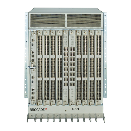
The following figure shows the port-side view of the X7-8 Director with installed blades identified. Note that the SX6 extension blades is not shown in the following figure, but would install in the same slots as the FC32-X7-48 or FC64-64 port blades. A maximum of four SX6 blades are supported. Broadcom X7-8-Install-IG100... - Page 16 5. Control Processor Blades (CPX7) – Slot 1 (upper), Slot 2 (lower) NOTE Depending on the fans and power supplies that are installed, airflow can be from the port side to the nonport side of the chassis or from the nonport side to the port side of the chassis. Broadcom X7-8-Install-IG100...
-
Page 17: Port-Side Slot Numbering
Slots 3–6 and slots 9–12 are restricted to port and extension blades. • Slots 7–8 are restricted to CR64-8 core blades. Nonport-Side View of the Device The following figure shows the nonport-side view of the X7-8 Director with all fan and power supply assemblies installed. Broadcom X7-8-Install-IG100... - Page 18 Although not illustrated, the chassis label that contains the serial number, SKU, and WWN is located on the lower portion of the chassis, below the fan assemblies. Broadcom X7-8-Install-IG100...
-
Page 19: Preparing For Installation
If the installation requires a different power cord than the one supplied with the device, make sure that you use a power cord displaying the mark of the safety agency that defines the regulations for power cords in your country. The mark is your assurance that the power cord can be used safely with the device. Broadcom X7-8-Install-IG100... - Page 20 Laser Precautions DANGER Use only optical transceivers that are qualified by Broadcom and comply with the FDA Class 1 radiation performance requirements defined in 21 CFR Subchapter I, and with IEC 60825 and EN60825. Optical products that do not comply with these standards might emit light that is hazardous to the eyes.
-
Page 21: Facility Requirements
Configurations with fewer blades or ports require less time. These time estimates assume a prepared installation site and appropriate power and network connectivity. Broadcom X7-8-Install-IG100... - Page 22 Obtaining a USB drive pretested by 20 minutes Use a USB drive that has been test- Broadcom validated (verified) by Broadcom (Brocade): • SanDisk 32 CZ48 USB 3.0 Flash Drive (SDCZ48-032G-UAM46) • SanDisk 16 CZ48 USB 3.0 Flash Drive (SDCZ48-016G-UAM46) •...
-
Page 23: Shipped Items
Initial Setup and Verification • Port and Extension Blades (if required to install) • Power Supply Assemblies (if required to install) Review the safety precautions. Safety Precautions. Plan the installation. Obtain the appropriate rack mount kit. See Mounting Options. Broadcom X7-8-Install-IG100... - Page 24 Set the date and time. • tstimezone Use the command to display and set the time zone. • tsclockserver Use the command to synchronize the time with an external NTP server. Setting the Date and Time for more information. Broadcom X7-8-Install-IG100...
- Page 25 Backing Up the Configuration for more information. shutdown Optional: Power off the devices. Enter the command and wait for the device to power down, and then unplug the power cords. See Powering Down the Chassis for more information. Broadcom X7-8-Install-IG100...
-
Page 26: Mounting The Device
NOTE The preceding rack mount kits are supported for these devices on the publication date of this guide. For current support information, contact your Broadcom representative. Mounting Precautions The following precautions specifically apply to mounting the device. CAUTION Do not use the port cover tabs to lift the module. -
Page 27: Unpacking And Transporting The Device
Installing the 14U Rack Mount Kit for Four-Post Racks (XBR-DCX-0120 and XBR-DCX-0152) Use the following instructions to install a modular device in a 48.3 cm (19-in.) EIA rack using the 14U Rack Mount Kit for Four-Post Racks (XBR-DCX-0120 and XBR-DCX-0152). Two rack-mount kits are available. Broadcom X7-8-Install-IG100... -
Page 28: Time And Items Required
For rack rails with square holes be set to 92 cm-kg [80 in.-lb]) 3/8 in. (0.953 cm) alignment washer For rack rails with square holes NOTE Depending on the device and installation, not all the parts may be used on the device type. Broadcom X7-8-Install-IG100... -
Page 29: Assembling The Rack Hardware
7. 1/4-20 x 1/2 in. (1.27 cm) Panhead Phillips Screw with Thread Locker (for cabinets that have rails with square holes) 8. cm 3/8 in. (0.953 cm) Alignment Washer (for cabinets that have rails with square holes) Assembling the Rack Hardware Attach the left and right rack mount shelf brackets to the rack rails. Broadcom X7-8-Install-IG100... - Page 30 Position the left and right rack mount shelf brackets and attach them to the rack rails. Use eight screws and alignment washers per bracket (four on each end). Tighten the screws to a torque of 92 cm-kg (80 in.-lb) Broadcom X7-8-Install-IG100...
- Page 31 5. Attach the clip nuts (for rails with round holes) or retainer nuts (for rails with square holes) to the vertical rails on the exhaust aisle side of the rack (see the previous figure). These clip nuts are used for securing the port side of the Broadcom X7-8-Install-IG100...
-
Page 32: Installing The Device In The Rack
Do not align the clip or retainer nuts with the top or bottom holes of the mounting bracket because the screw heads will interfere with the door. Installing the Device in the Rack Use the following procedure to install the device in the rack. Broadcom X7-8-Install-IG100... - Page 33 4. If applicable, lock the wheels of the lift. 5. Gently slide the device onto the shelf brackets, ensuring that it remains supported during the transfer. Figure 6: Positioning the Device for Installation in a Rack 1. Rack Broadcom X7-8-Install-IG100...
- Page 34 6. Fasten the port side of the device to the rack rails. Use three 10-32 x 5/8 inch (1.58 cm) screws per rail. Tighten the screws to a torque of 37 cm-kg. (32 in.-lb). See the following figure. Figure 7: Attaching the Port Side of the Device to Rack Rails 1. 10-32 x 5/8 in. (1.58 cm) Panhead Phillips Screw with Washer Broadcom X7-8-Install-IG100...
-
Page 35: Installing The 14U Chassis Mid-Mount Rack Kit For Two-Post Racks (Xbr-Dcx-0121)
Hydraulic or assisted lift with a minimum raise of 140 cm (55 in.) and a minimum capacity of 113 kg (250 lbs) Parts List The following parts are provided with the 14U Chassis Mid-Mount Rack Kit for Two-Post Racks (XBR-DCX-0121). Broadcom X7-8-Install-IG100... - Page 36 4. Adapter, Rear, Mid-Mount, Left 5. Screw, 10-32 x 3/8-in. Panhead Phillips, ST, Zinc (requires a torque of 37 cm-kg [32 in.-lbs]). NOTE Depending on the device type, certain installations might not use all of the listed parts. Broadcom X7-8-Install-IG100...
-
Page 37: Assembling The Rack Hardware
3. Verify that the rear edge of the front tray is seated into the front edge of the rear tray. Figure 9: Attaching the Rear Tray to the Rack Rails 2. Tray, Rear, Mid-Mount, Chassis 3. Adapter, Rear, Mid-Mount, Right 4. Adapter, Rear, Mid-Mount, Left 5. Screws Broadcom X7-8-Install-IG100... -
Page 38: Installing The Device In The Rack
1. Tray, Front, Mid-Mount, Chassis 5. Screws Installing the Device in the Rack DANGER Use safe lifting practices when moving the product. NOTE A fully populated device requires a hydraulic lift or an assisted lift to install into a rack. Broadcom X7-8-Install-IG100... - Page 39 3. If applicable, lock the wheels of the lift. 4. Slide the device into the trays until the front edge of the device is seated against the front tray. Figure 11: Placing the Device in the Trays 1. Tray, Front, Mid-Mount, Chassis Broadcom X7-8-Install-IG100...
- Page 40 7. Use six screws (Item 5) to attach the lip on each side of the front tray to the lip on the front of the device. NOTE Do not use the top or bottom holes of the Brocade mounting bracket because the door will interfere with the screw heads. Broadcom X7-8-Install-IG100...
- Page 41 ® X7-8-Install-IG100 Installation Guide Brocade X7-8 Director Hardware Installation Guide Figure 12: Attaching Trays to the Device 8. Reinstall the device door. Broadcom X7-8-Install-IG100...
-
Page 42: Initial Setup And Verification
--show You use the command to determine enabled licenses and license keys. chassis ID is the License Id/switchWwn. Record the license key and chassis ID for future reference. Broadcom X7-8-Install-IG100... -
Page 43: Items Required
15.2 cm (6 in.) and are routed to avoid stress. • Remember that power is supplied to the device as soon as the first power supply is connected to a power source. Broadcom X7-8-Install-IG100... -
Page 44: Connecting The Power Cord To Ac Power Supplies
Perform steps in this section to apply power to the dual-function high-voltage AC and DC (HVAC/HVDC) power supply. This power supply converts high-voltage DC or AC input to appropriate DC power for the device. Make sure that you observe the electrical caution and danger statements in Safety Precautions when connecting this power supply. Broadcom X7-8-Install-IG100... - Page 45 The connector on the power cord is keyed so that it only fits one way into the power supply connector. Note that the connector's latch should be positioned under the connector and will latch when the power cord connector is fully inserted into the power supply. Broadcom X7-8-Install-IG100...
- Page 46 200–277 VAC lines are required for full N+N redundancy. For details on power supplies required for operation and high availability, see "Power Supply Requirements" and "Power Consumption" tables in the Brocade X7 Director Technical Specifications. DANGER High Touch Current. Earth connection essential before connecting supply. Broadcom X7-8-Install-IG100...
-
Page 47: Using Hvac/Hvdc Power Cords
The following table defines the function of the 14 AWG wires in the power cable: Table 9: HVAC/HVDC Power Cable Wire Label Color Function Brown Return positive (+) – Blue Negative (-) Green with yellow stripe Earth ground (PE) Broadcom X7-8-Install-IG100... -
Page 48: Establishing A Serial Connection To The Device
The active CP is indicated by an illuminated blue LED, labeled "Active," on the CP blade front panel. If the serial port on the workstation is RJ-45 instead of RS-232, remove the adapter on the end of the serial cable and insert the exposed RJ-45 connector into the RJ-45 serial port on the workstation. Broadcom X7-8-Install-IG100... - Page 49 Passwords can be 8 to 40 characters long. They must begin with an alphabetic character. They can include numeric characters, periods (.), and underscores (_) only. Passwords are case-sensitive, and they are not displayed when you enter them on the command line. For more information on passwords, refer to the Brocade Fabric OS Administration Guide. Broadcom X7-8-Install-IG100...
-
Page 50: Configuring The Ip Addresses
Following is an example configuration for setting the chassis IP address. swDir:admin> ipaddrset -chassis DHCP [Off]: Ethernet IP Address [10.0.0.0]:192.168.1.1 Ethernet Subnetmask [255.0.0.0]:255.255.240.0 IP address is being changed... 3. Set up the CP0 IP address by entering the ipaddrset -cp 0 command: Broadcom X7-8-Install-IG100... -
Page 51: Establishing An Ethernet Connection To The Device
4. Complete any additional device configuration procedures for the device using one of the following steps: • Log on to the device using a serial console connection and admin logon. • Log on to the device through a telnet session using the chassis management IP address and admin logon. Broadcom X7-8-Install-IG100... -
Page 52: Setting The Domain Id
A telnet session using the chassis management IP address. 2. Log on to the device using admin . If you have not changed the default password, use password . 3. Enter the date command, using the following syntax: date "mmddHHMMyy" The values are: Broadcom X7-8-Install-IG100... -
Page 53: Setting The Time Zone
Enter number or control-D to quit ? • Enter tsTimeZone [-houroffset [,minuteoffset ]] command as follows: • For Pacific Standard Time, enter tsTimeZone -8,0 . • For Central Standard Time, enter tsTimeZone -6,0 . • For Eastern Standard Time, enter tsTimeZone -5,0 . Broadcom X7-8-Install-IG100... -
Page 54: Synchronizing The Local Time With An External Source
192.168.126.60 Updating Clock Server configuration...done. Updated with the NTP servers Customizing the Chassis and Switch Name Refer to the considerations and rules for creating switch, fabric, and chassis names listed in the Brocade Fabric OS Administration Guide. Broadcom X7-8-Install-IG100... -
Page 55: Verifying Installed Licenses And The License Key
ID). The chassis ID is required to obtain and activate licenses for the device. 5. Store and record the license key file for future reference. Refer to the Brocade Fabric OS Software Licensing User Guide for more information. Broadcom X7-8-Install-IG100... -
Page 56: Verifying Correct Operation
Besides saving configuration files to an FTP server or local file system, you can save to a test validated USB device with the usbstorage command. NOTE Use a USB drive that has been test validated (verified) by Broadcom (Brocade): • SanDisk 32 CZ48 USB 3.0 Flash Drive (SDCZ48-032G-UAM46) •... -
Page 57: Powering Down The Chassis
® X7-8-Install-IG100 Installation Guide Brocade X7-8 Director Hardware Installation Guide These drives are not orderable from Broadcom but are generically-branded and can be purchased from other suppliers. 1. Log on to the device using one of the following methods: •... - Page 58 Disconnect the power cable from the power supply. NOTE The latch for the power cable connector is positioned under the connector. Press on the latch using a small screwdriver or other tool to unlatch from the power supply. Broadcom X7-8-Install-IG100...
- Page 59 ® X7-8-Install-IG100 Installation Guide Brocade X7-8 Director Hardware Installation Guide 1. Power Cable 2. Connector Latch Broadcom X7-8-Install-IG100...
-
Page 60: Installing Transceivers And Cables
40GbE QSFP, SR4, LR4, ER4 Fixed 40GbE CR64-4 core 4xGen 7 ICL QSFP56 SWL Fixed Gen 7 ICL speed routing blade 4x32Gb/s QSFP28, SWL Manual port speed 32Gb/s or 16Gb/s configuration, 32Gb/s default 4x32Gb/s QSFP28, LWL (2 km) Fixed 32Gb/s Broadcom X7-8-Install-IG100... - Page 61 The following figures show examples of QSFP to QSFP and QSFP breakout cables. Figure 13: QSFP to QSFP Standard Cables 1. QSFP Quad Connector Figure 14: QSFP to SFP Breakout/Cables This is only useful for ICLs if connecting to a patch panel. 1. QSFP MPO Connector 2. SFP Connectors Broadcom X7-8-Install-IG100...
-
Page 62: Port And Extension Blade Transceivers
X7-8 Director Hardware Installation Guide DANGER Use only optical transceivers that are qualified by Broadcom and comply with the FDA Class 1 radiation performance requirements defined in 21 CFR Subchapter I, and with IEC 60825 and EN60825. Optical products that do not comply with these standards might emit light that is hazardous to the eyes. -
Page 63: Core Routing Blades
The following list and illustration show the types of QSFPs installed in core routing blades: • Separate MTP cable and transceiver. The transceiver is inserted into the blade port and the cable plugs into a QSFP on the other end of the ICL. Broadcom X7-8-Install-IG100... - Page 64 These colors are also applied to the port map labels on each blade faceplate to indicate ports belonging to the same trunking groups. For details on the following subjects, refer to the "Inter-Chassis Links' section of the Brocade Fabric OS Administration Guide: Broadcom X7-8-Install-IG100...
-
Page 65: Time And Items Required
Precautions Specific to Transceivers and Cables DANGER Use only optical transceivers that are qualified by Broadcom and comply with the FDA Class 1 radiation performance requirements defined in 21 CFR Subchapter I, and with IEC 60825 and EN60825. Optical products that do not comply with these standards might emit light that is hazardous to the eyes. -
Page 66: Cleaning The Fiber-Optic Connectors
NOTE For current information on qualified transceivers supported by this device, refer to the Brocade Fibre Channel Transceiver Support Matrix and Brocade Transceiver Modules on www.broadcom.com. The device supports only Brocade-qualified transceivers. If you use an unqualified transceiver, the switchshow command output shows the port in a Mod_Inv state. - Page 67 Cables are keyed so that they can be inserted in only one way. If a cable does not slide in easily, ensure that it is correctly oriented. Do not insert any unsupported cable intended for another type of transceiver into a regular SFP+ transceiver. You may damage the cable as well as the transceiver. Broadcom X7-8-Install-IG100...
-
Page 68: Replacing An Sfp+ Transceiver
Pull the transceiver out from the port slightly using the bail, and then gasp the transceiver with your fingers and slide it straight out of the port. Broadcom X7-8-Install-IG100... -
Page 69: Installing A Qsfp Transceiver
If a transceiver does not slide in easily, ensure that it is correctly oriented. Push the correctly oriented transceiver into the port until it is firmly seated and the latching mechanism clicks. NOTE Always use the transceiver pull tab to insert or remove the QSFP transceivers, as the transceiver might be hot. Broadcom X7-8-Install-IG100... -
Page 70: Replacing A Qsfp Transceiver
2. Grasp the transceiver pull tab and gently pull the transceiver straight out from the port. NOTE Grasp the pull tab near the body of the transceiver to reduce the chances of bending the pull tab. Since the transceiver may be hot, always use the pull tab and avoid touching the transceiver body. Broadcom X7-8-Install-IG100... -
Page 71: Verifying The Operation Of New Transceivers
-slot , where slot is the slot number For output examples and additional information on Fabric OS commands, see Using Monitoring Commands and the Brocade Fabric OS Command Reference Manual. For more information about error messages, refer to the Brocade Fabric OS Message Reference Manual. Broadcom X7-8-Install-IG100... -
Page 72: Monitoring The Device
See the following figure and table to interpret the LED patterns for the FC32-X7-48 blade. The LED patterns temporarily change during the POST and other diagnostic tests. Figure 26: FC32-X7-48 Port Blade LEDs 1. Blade Power LED 2. Blade Status LED Broadcom X7-8-Install-IG100... - Page 73 The port is online, with traffic No action is required. flowing through the port. Steady amber The port is receiving light or Reset the port from the signal carrier, but it is not online workstation using the portable or portCfgPersistentEnable yet. command. Broadcom X7-8-Install-IG100...
-
Page 74: Interpreting Fc64-48 Port Blade Leds
See the following figure and table to interpret the LED patterns for the FC64-48 blade. The LED patterns temporarily change during POST and other diagnostic tests. Figure 27: FC64-48 Port Blade LEDs 1. Blade Power LED 2. Blade Status LED 3. Status LED for Right FC Port Broadcom X7-8-Install-IG100... - Page 75 The port is online, with traffic No action is required. flowing through the port. Steady amber The port is receiving light or Reset the port from signal carrier, but it is not online the workstation using portEnable yet. portCfgPersistentEnable command. Broadcom X7-8-Install-IG100...
-
Page 76: Interpreting Fc32-64 Port Blade Leds
The port is beaconing. No action is required. Interpreting FC32-64 Port Blade LEDs See the following figure and table to interpret the LED patterns for the FC32-64 blade. The LED patterns temporarily change during POST and other diagnostic tests. Broadcom X7-8-Install-IG100... - Page 77 40GbE QSFP in breakout mode, each of the four LEDs indicates the status of a 10GbE port. In nonbreakout mode, the primary (top) LED indicates the status of the unified 40GbE port. The following table describes the blade LED patterns and the recommended actions for those patterns. Broadcom X7-8-Install-IG100...
- Page 78 Slow-flashing amber (on 1.28 Port is disabled due Reset the port from seconds, then off 1.28 seconds) to diagnostic tests or the workstation using portDisable portDisable portCfgPersistentEnable portCfgPersistentEnable commands. command. Broadcom X7-8-Install-IG100...
-
Page 79: Interpreting Extension Blade Leds
See the following figure and table to interpret the LED patterns on the SX6 extension blade. The LED patterns temporarily change during POST and other diagnostic tests. Figure 29: SX6 Extension Blade LEDs 1. Blade Power LED 2. Blade Status LED 3. Right 40GbE QSFP (Port 0) Status LED 4. Left 40GbE QSFP (Port 1) Status LED Broadcom X7-8-Install-IG100... - Page 80 Slow-flashing green (on 1 The port is online but Verify that the correct device is second, then off 1 second) segmented, indicating a attached to the chassis. loopback plug or cable or an incompatible switch. Broadcom X7-8-Install-IG100...
-
Page 81: Interpreting Control Processor Blade Leds
See the following figure and table to interpret the LED patterns on the CPX7 blade. The LED patterns temporarily change during POST and other diagnostic tests. The following table describes the CP blade LED patterns and the recommended actions for those patterns. Broadcom X7-8-Install-IG100... - Page 82 Occasionally, the LED patterns for the CPX6 blade differ from those found on the CPX7 blade. See the following figure and table to interpret the LED patterns on the CPX7 blade. Broadcom X7-8-Install-IG100...
-
Page 83: Interpreting Core Routing Blade Leds
If an link is inactive, ensure that the blade has power, the Ethernet cable is firmly seated, and the connected device is functioning. Interpreting Core Routing Blade LEDs See the following figure and table to interpret the LED patterns on the CR64-4 blade. The LED patterns temporarily change during POST and other diagnostic tests. Broadcom X7-8-Install-IG100... - Page 84 X7-8-Install-IG100 Installation Guide Brocade X7-8 Director Hardware Installation Guide Figure 30: CR64-8 Core Routing Blade LEDs 1. Blade Power LED 2. Blade Status LED 3. QSFP Status LED for Right QSFP Port 4. QSFP Status LED for Left QSFP Port Broadcom X7-8-Install-IG100...
-
Page 85: Interpreting Wwn Card Leds
See the following figure and table to interpret the LED patterns of installed WWN cards. LEDs for WWN card 1 and WWN card 2 are located on the WWN card (logo) bezel between the power supplies on the nonport side of the device. The LED patterns may temporarily change during POST and other diagnostic tests. Broadcom X7-8-Install-IG100... -
Page 86: Interpreting Power Supply Leds
See the following information to interpret the LED patterns on the power supply. The LED patterns may temporarily change during POST and other diagnostic tests. The Brocade X7-8 Director can have up to four power supplies. Figure 32: AC Power Supply LED 1. - Page 87 48V is out of range. Disconnect the power cable from the power then off 5 seconds. supply, remove and reinsert the power supply, and then reconnect the power cable to restart. If the status persists, replace the power supply assembly. Broadcom X7-8-Install-IG100...
- Page 88 If status persists, replace the power supply assembly. Broadcom X7-8-Install-IG100...
-
Page 89: Interpreting Fan Assembly Leds
See the following figure and table to interpret the LED patterns on fan assemblies. The LED patterns may temporarily change during POST and other diagnostic tests. The X7-8 Director has three fan assemblies. Figure 34: Fan Assembly LEDs 1. Power LED 2. Status LED Broadcom X7-8-Install-IG100... -
Page 90: Interpreting Post And Boot Results
Review the system error log using the errShow or errDump commands. Any errors detected during POST are written to the system log, which is accessible through the errShow command. For information about error messages, refer to the Brocade Fabric OS Message Reference Manual Manual. Broadcom X7-8-Install-IG100... -
Page 91: Boot
Output for the following commands is provided: • chassisShow • errDump • fanShow • haShow • HistoryShow • psShow • sensorShow • sfpShow • SupportSave • switchShow • tempShow Broadcom X7-8-Install-IG100... -
Page 92: Errdump And Errshow
Fan 1 is Ok, speed is 7518 RPM Fan 2 is Ok, speed is 7471 RPM Fan 3 is Ok, speed is 7434 RPM haShow Use the haShow command to display the control processor (CP) status. The display includes the following information: Broadcom X7-8-Install-IG100... -
Page 93: Historyshow
Inserted at Mon Jun 13 13:59:11 2016 Factory Part Number: 23-0000163-01 Factory Serial Number: DUE2M03M04S SW BLADE Slot 3 Inserted at Mon Jun 13 13:59:12 2016 Factory Part Number: 60-1003336-01 Factory Serial Number: EAL0338L006 Unit 1 Inserted at Mon Jun 13 13:59:13 2016 Broadcom X7-8-Install-IG100... - Page 94 Factory Serial Number: DYK0338L008 CP BLADE Slot 2 Inserted at Mon Jun 13 13:59:20 2016 Factory Part Number: 60-1003201-09 Factory Serial Number: DYK0338L00E SW BLADE Slot 12 Inserted at Mon Jun 13 14:29:57 2016 Factory Part Number: 60-1003200-07 Broadcom X7-8-Install-IG100...
-
Page 95: Psshow
23: (Temperature) is Ok, value is 51 C sensor 24: (Temperature) is Ok, value is 48 C sensor 25: (Temperature) is Ok, value is 42 C sensor 26: (Temperature) is Ok, value is 30 C sensor 27: (Temperature) is Ok, value is 60 C Broadcom X7-8-Install-IG100... -
Page 96: Sfpshow
8: -- Slot 3/Port 9: -- Slot 3/Port 10: -- Slot 3/Port 11: -- Slot 3/Port 12: -- Slot 3/Port 13: -- Slot 3/Port 14: -- Slot 3/Port 15: -- Slot 4/Port 0: -- Slot 4/Port 1: -- Broadcom X7-8-Install-IG100... - Page 97 6/Port 13: -- Slot 6/Port 14: -- Slot 6/Port 15: -- Slot 9/Port 0: -- Slot 9/Port 1: -- Slot 9/Port 2: -- Slot 9/Port 3: -- Slot 9/Port 4: -- Slot 9/Port 5: -- Slot 9/Port 6: -- Broadcom X7-8-Install-IG100...
- Page 98 2: -- Slot 12/Port 3: -- Slot 12/Port 4: -- Slot 12/Port 5: -- Slot 12/Port 6: -- Slot 12/Port 7: -- Slot 12/Port 8: -- Slot 12/Port 9: -- Slot 12/Port 10: -- Slot 12/Port 11: -- Broadcom X7-8-Install-IG100...
- Page 99 Slot 10/Port 23: -- Slot 10/Port 24: -- Slot 10/Port 25: -- Slot 10/Port 26: -- Slot 10/Port 27: -- Slot 10/Port 28: -- Slot 10/Port 29: -- Slot 10/Port 30: -- Slot 10/Port 31: -- Slot 11/Port 16: -- Broadcom X7-8-Install-IG100...
- Page 100 6/Port 33: id (sw) Vendor: BROCADE Serial No: JAF315410000NDL Speed: 8,16,32_Gbps Slot 6/Port 34: id (sw) Vendor: BROCADE Serial No: JAF31542000010P Speed: 8,16,32_Gbps Slot 6/Port 35: id (sw) Vendor: BROCADE Serial No: JAF315410000NNZ Speed: 8,16,32_Gbps Slot 6/Port 36: -- Slot 6/Port 37: -- Broadcom X7-8-Install-IG100...
- Page 101 Slot 12/Port 33: -- Slot 12/Port 34: -- Slot 12/Port 35: -- Slot 12/Port 36: -- Slot 12/Port 37: -- Slot 12/Port 38: -- Slot 12/Port 39: -- Slot 12/Port 40: -- Slot 12/Port 41: -- Slot 12/Port 42: -- Broadcom X7-8-Install-IG100...
-
Page 102: Slotshow
SFTP parameters set by supportFtp . The -n operand turns off confirmation prompting. Gen7-4:admin> supportftp Host IP Addr: 10.154.6.41 User name: ak4089752 Remote Dir: /tftpboot/dumps/supportsave/test01/x7-4 Auto Upload protocol: sftp SCP/SFTP port: Auto-FTP: Gen7-4:FID128:root> supportsave -n -c Saving support information: Broadcom X7-8-Install-IG100... - Page 103 32.760156 secs 39.745212 secs 34.3/34.3/34.3 DP8/0 RAS_PRE 115.934 KB 0.000 KB 31.990007 secs 39.617567 secs 34.1/34.3/34.3 Gen7-4 SSHOW_AMP 0.137 KB 0.000 KB 1.113314 secs 3.57106 secs 7.0/2.2/1.1 Gen7-4 SSHOW_FICON 375.985 KB 0.000 KB 16.2374 secs 18.413898 secs 5.9/1.9/1.0 Broadcom X7-8-Install-IG100...
- Page 104 0.978420 secs 2.908962 secs 6.8/4.9/2.4 Gen7-4_ls20 FLOW_VISION_LOG 1.279 KB 0.000 KB 0.960104 secs 2.662789 secs 6.8/4.9/2.4 switch_25 FLOW_VISION_LOG 1.279 KB 0.000 KB 0.990517 secs 2.428836 secs 6.8/4.9/2.4 Gen7-4 CEEDEBUG 9.996 KB 0.000 KB 62.543965 secs 64.17881 secs 7.9/4.6/2.2 Broadcom X7-8-Install-IG100...
-
Page 105: Tempshow
Sensor index (when command issued with the --detail option) • Sensor state (OK or absent) • Temperature in both Centigrade and Fahrenheit The following is an example of tempShow output: chassisX7-8:admin> tempshow Sensor Slot Sensor State Centigrade Fahrenheit Index =================================================================== Broadcom X7-8-Install-IG100... -
Page 106: Running Diagnostic Tests
Running Diagnostic Tests Diagnostic tests are automatically run during POST to check the status of the device. Any error messages generated during POST are sent to the error logs and to the serial console if the console is connected. Broadcom X7-8-Install-IG100... - Page 107 For more information about diagnostic tests and how to run them, refer to the Brocade Fabric OS Administration Guide and the Brocade Fabric OS Command Reference Manual. For information about system error messages (errShow or errDump) , refer to the Brocade Fabric OS Troubleshooting and Diagnostics Guide. Broadcom X7-8-Install-IG100...
-
Page 108: Port And Extension Blades
Amber blade status LED • Bicolor green/amber FC port status LEDs For details on interpreting LED operation, see Interpreting FC32-X7-48 Port Blades. FC32-X7-48 Port Blade Numbering and Trunking The following figure shows how ports are numbered on the blade: Broadcom X7-8-Install-IG100... - Page 109 ® X7-8-Install-IG100 Installation Guide Brocade X7-8 Director Hardware Installation Guide Figure 35: FC32-X7-48 Blade Port Numbering 1. FC Ports 0–23 (numbered bottom to top) Broadcom X7-8-Install-IG100...
-
Page 110: Fc64-48 Port Blade Overview
Supported Transceivers and Cables. • 64Gb/s SFP+ transceivers supporting speeds 64Gb/s, 32Gb/s, and 16Gb/s. • 32Gb/s SFP+ transceivers supporting speeds of 32Gb/s, 16Gb/s, and 8Gb/s. • 10Gb/s SFP+ transceivers supporting 10Gb/s. Port blades contain the following LED indicators: Broadcom X7-8-Install-IG100... -
Page 111: Fc64-48 Port Blade Numbering And Trunking
Amber blade status LED • Bicolor green/amber FC port status LEDs For details on interpreting LED operation, see Interpreting FC64-48 Port Blade LEDs. FC64-48 Port Blade Numbering and Trunking The following figure shows how ports are numbered on the blade. Broadcom X7-8-Install-IG100... - Page 112 ® X7-8-Install-IG100 Installation Guide Brocade X7-8 Director Hardware Installation Guide Figure 36: FC64-48 Blade Port Numbering 1. FC Ports 0–23 (numbered bottom to top) Broadcom X7-8-Install-IG100...
-
Page 113: Fc32-64 Port Blade Overview
8. Up to eight hot-swappable port blades can be installed in a single chassis to provide up to 384 32Gb/s FC ports. • It is recommended that three fan assemblies be installed on the X7-8 chassis if blades are being used. Broadcom X7-8-Install-IG100... -
Page 114: Fc32-64 Port Blade Numbering And Trunking
For more details on FCoE, Flexport, and breakout mode features and commands, refer to the Brocade Fabric OS Administration Guide and Brocade Fabric OS Command Reference Manual. FC32-64 Port Blade Numbering and Trunking The following illustration shows how ports are numbered on the blade. Broadcom X7-8-Install-IG100... - Page 115 On the blade, ports belonging to the same port group are indicated with the same color border beneath the port on the blade label. Ports belonging to the same ASIC are indicated by a border with a similar color tone. Broadcom X7-8-Install-IG100...
-
Page 116: Extension Blade Overview
Channel and IP I/O to pass through the IP WAN using extension tunnels. The 10GbE or 1GbE ports operate at 10Gb/ s or 1Gb/s fixed speeds with appropriate 10Gb/s or 1Gb/s transceivers installed. The 40GbE QSFP ports operate at 40Gb/s fixed speed. Extension blades have the following LED indicators: Broadcom X7-8-Install-IG100... -
Page 117: Extension Features
A maximum of 20 tunnels (VE_Ports) can be configured for all GbE ports. – The maximum committed rate of a single circuit is 10Gb/s, whether configured on a 10GbE or 40GbE port. • FCIP and hybrid mode (FC + IP) modes. Broadcom X7-8-Install-IG100... -
Page 118: Sx6 Blade Port Numbering And Trunking
5. FC Ports 0, 1, 2, 3, 8, 9, 10, 11 (bottom to top) 6. FC Ports 4, 5. 6, 7, 12, 13, 14, 15 (bottom to top) Following are the eight-port Fibre Channel port groups for configuring trunk groups or "trunks": Broadcom X7-8-Install-IG100... -
Page 119: Blade-Specific Precautions
The slotShow command does not show that the blade is enabled. • The errShow command displays error log messages one at a time. • Any of the following messages display in the error log or "show" command output: Broadcom X7-8-Install-IG100... -
Page 120: Time And Items Required For Removal And Installation
SFP, SFP+, or SFP28 transceivers (as needed) • Optical and copper cables (as needed) NOTE For information about the transceivers that are qualified for this Brocade device, see Supported Transceivers Cables. Removing a Blade Before removing the blade, consider the following: Broadcom X7-8-Install-IG100... - Page 121 12. Continue pulling the blade from the slot by the blade edges. As you slide out the blade, place one hand under it for support. Do not support the blade by the injector handles after removal. Figure 39: Removing and Replacing Port or Extension Blade Broadcom X7-8-Install-IG100...
-
Page 122: Installing A Blade
To avoid damaging blade and chassis, do not push the blade into a slot or pull the blade from a slot using the ejector handles. When the blade face is about 2.54 cm (1 in.) from the chassis, you should feel resistance as the blade connectors meet the backplane connectors. Broadcom X7-8-Install-IG100... -
Page 123: Verifying Blade Operation
– Displays error log messages one at a time. For output examples and additional information on Fabric OS commands, see Using Monitoring Commands and the Brocade Fabric OS Command Reference Manual. For more information about error messages, refer to the Brocade Fabric OS Message Reference Manual. Broadcom X7-8-Install-IG100... -
Page 124: Core Routing Blades
ICL connections for up to nine separate directors in a full-mesh topology and 12 directors in a core-to-edge topology. This core switch blade is compatible only with the Brocade X7-8. Core routing blades contain the following LED indicators: •... - Page 125 QSFP ports are numbered from 0 through 7 on the left side from bottom to top and from 8 through 15 on the right side from bottom to top. For information on supported QSFP transceivers, see Supported Transceivers and Cables. Broadcom X7-8-Install-IG100...
-
Page 126: Icl Trunking Groups
You cannot configure ISLs using ports on port blades and QSFP-based ICLs using ports on core routing blades concurrently on the same chassis. ISLs and ICLs can co-exist between a pair of chassis if the ISLs and ICLs are in different logical switches. Broadcom X7-8-Install-IG100... -
Page 127: Icl Cabling Configurations
The following illustration shows the minimum connectivity between a pair of X7-8 chassis: Figure 41: ICL Cable Connections between Two X7-8 Directors The following illustration shows the minimum connectivity between an X7-8 and X7-4 chassis: Broadcom X7-8-Install-IG100... - Page 128 Figure 42: ICL Cable Connections for the X6 Director (Sample Configuration) The following illustration shows the minimum conectivity between an X7-8 Director and a Gen 5 DCX8510-8 chassis: Figure 43: ICL Cable Connections for the X6 Director (Sample Configuration) The following requirements apply for ICLs: Broadcom X7-8-Install-IG100...
-
Page 129: Blade-Specific Precautions
Configuring ICLs between X6 Directors • Configuring ICLs between X6 Directors and DCX 8510 Director models Blade-Specific Precautions This document describes how to remove and replace a core routing blade. Observe the following precautions when replacing these blades: Broadcom X7-8-Install-IG100... -
Page 130: Faulty Core Routing Blade Indicators
For more information about error messages, refer to the Brocade Fabric OS Message Reference Manual. Time and Items Required The replacement procedure for the core switch blade takes approximately 30 minutes. The following items are required to replace the core switch blade. Broadcom X7-8-Install-IG100... -
Page 131: Replacing A Core Routing Blade
ICL ports on the other core routing blade. 4. Confirm that all of the ICL ports are persistently disabled (decommissioned) on the blade by logging into the physical switch and entering the portcfgpersistentdisable command. This command displays the status of ports in each chassis slot. Broadcom X7-8-Install-IG100... -
Page 132: Removing A Core Routing Blade
11. Pull the blade out from the slot slightly using the ejector handles until you can grasp the blade edges with your hands. Make sure that the blade has cooled sufficiently to touch. CAUTION To avoid damaging blade and chassis, do not push the blade into a slot or pull the blade from a slot using the ejector handles. Broadcom X7-8-Install-IG100... -
Page 133: Installing A Core Routing Blade
13. If the blade is not being replaced by another blade, install a filler panel and reinstall the chassis door. The filler panel is required for proper chassis cooling. The door is required to meet EMI compliance. Installing a Core Routing Blade Complete the following steps to install a core routing blade into an empty slot. Broadcom X7-8-Install-IG100... -
Page 134: Verifying Blade Operation
Perform the following tasks to verify the operation of the new blade: 1. Check the LED indicators on the blade's front panel. For information on interpreting LED patterns, see Interpreting Core Routing Blade LEDs. Enter the slotShow command and note any error conditions: Broadcom X7-8-Install-IG100... - Page 135 – Displays error log messages one at a time. For output examples and additional information on Fabric OS commands, see Using Monitoring Commands and the Brocade Fabric OS Command Reference Manual. For more information on error messages, refer to the Brocade Fabric OS Message Reference Manual. Broadcom X7-8-Install-IG100...
-
Page 136: Control Processor Blades
Control Processor Blade Overview The CPX7 control processor blades are half the slot height of other Brocade X7-8 Director blades. Two CPX7 control processor blades are stacked vertically in the half slots on the left side of the chassis to provide CP redundancy. CP0 is installed in slot 1, while CP1 is installed in slot 2. -
Page 137: Blade-Specific Precautions
CP blade to copy current firmware to the replaced standby CP blade, if necessary. However, you must disable high availability (HA) before inserting the new blade. DANGER For safety reasons, the ESD wrist strap should contain a series 1 megaohm resistor. Broadcom X7-8-Install-IG100... -
Page 138: Blade Fault Indicators
Follow all steps for one blade, and then repeat the same steps to replace the other blade. 1. Prepare for replacing the blade by following all steps under Preparing for Replacement. 2. Remove the blade from the slot by following all steps under Removing a Blade. Broadcom X7-8-Install-IG100... -
Page 139: Time And Items Required For Replacement
This command saves the port-to-area addressing mode configuration files to the folder specified. Be sure to upload the configuration using the -map option for a FICON-enabled device if port-bound addressing is used. For more information, refer to the Brocade Fabric OS Command Reference Manual. Broadcom X7-8-Install-IG100... -
Page 140: Replacing A Cp Blade
The device continues to operate while replacing a blade if the redundant blade is active and failover does not occur. • Cold-swap procedure. Use this procedure to replace CP blades after removing power to the device. Broadcom X7-8-Install-IG100... -
Page 141: Hot-Swap Procedure
9. Continue pulling the blade from the slot by the blade edges. As you slide out the blade, place one hand under it for support. Do not support the blade by the injector handles after removal. Figure 47: Removal and Replacement of the Control Processor Blade (CPX7) on an X7-8 Director Broadcom X7-8-Install-IG100... -
Page 142: Installing A Blade
If the replacement CP blade has a different version of Fabric OS, bring both blades to the same firmware version. Once you have installed the replacement CP blade, determine the version of firmware on the replacement CP blade and upgrade it if necessary. Broadcom X7-8-Install-IG100... -
Page 143: Verifying And Synchronizing Firmware On Blades
If the standby CP is unresponsive, you can try unplugging the new CP blade, running haDisable on the active CP blade, and plugging the new CP blade back in. At that point, you can repeat Step 1 to begin the verification process again. Broadcom X7-8-Install-IG100... - Page 144 The command displays a running account of the progress of the firmwareDownload command (if it is still running) until the command has completed. The final message is similar to the following and will appear with a date and time stamp. Broadcom X7-8-Install-IG100...
- Page 145 This section assumes that the new firmware has already been copied onto the USB device. Although folders are optional, if an administrator desires to use them, the folder structure on the USB device might be as follows: • brocade> – config – firmware (Contains the specific release you are installing) – firmwareKey – support Broadcom X7-8-Install-IG100...
- Page 146 2010/06/17-14:56:50, [SULB-1002], 910, SLOT 2 | CHASSIS, INFO, Brocade_X6, Firmwaredownload command has completed successfully. NOTE The time stamp on the co-CPU may not be in sync with the main CPU on the blade. This is not a cause for concern. Broadcom X7-8-Install-IG100...
-
Page 147: Cold-Swap Procedure
8. Continue pulling the blade from the slot by the blade edges. As you slide out the blade, place one hand under it for support. Do not support the blade by the injector handles after removal. Figure 48: Removal and Replacement of the Control Processor Blade (CPX7) on an X7-8 Director Broadcom X7-8-Install-IG100... -
Page 148: Installing A Blade
1. Tighten the captive screws for each ejector using a No. 1 Phillips screwdriver. NOTE Be sure that the captive screws are tightened. If they are not tightened, high pressure from fan operation may unseat the blade from chassis connectors. Broadcom X7-8-Install-IG100... -
Page 149: Completing The Replacement
CP firmware and the blade's firmware and triggers the auto-leveling process. This auto-leveling process automatically updates the application blade firmware to match the active CP blade. At the end of the auto- leveling process, the active CP and extension blades will run the same version of the firmware. Broadcom X7-8-Install-IG100... -
Page 150: Verifying Blade Operation
–Displays error log messages one at a time. Using Monitoring Commands and the Brocade Fabric OS Command Reference Manual for output examples and additional information on Fabric OS commands. For more information about error messages, refer to the Brocade Fabric OS Message Reference Manual. Broadcom X7-8-Install-IG100... -
Page 151: Wwn Cards
The WWN cards are located behind the WWN bezel (logo bezel) on the nonport side of the device between the power supplies. The bezel must be removed to access the card trays. The following figure illustrates the WWN card location and numbering. Broadcom X7-8-Install-IG100... -
Page 152: Precautions Specific To Wwn Cards
WWN Card Fault Indicators Before replacing a WWN card, verify that the replacement is necessary. Any of the following events can indicate that cards require replacement: Broadcom X7-8-Install-IG100... - Page 153 WWN #1 not presentor<timestamp>, [EM-1036], <sequence-number>, WARNING, <system-name>, <FRU Id> is not accessible. Writing to the FRU history log 0x24c (fabos): Switch: switchname, Error EM-HIL_FAIL, 2, HIL Error: hilSetFruHistory ) has failed. hilSetFruHistory failed, rc=-3 for SLOT 3 Broadcom X7-8-Install-IG100...
-
Page 154: Wwn Card Replacement Task Guide
, and the output will direct you to call Brocade Technical Support. For other problems, running wwnrecover can pinpoint the problem and, in some cases, permit you to fix it. Mismatched data can be resolved, and corrupt data can sometimes be recovered. Broadcom X7-8-Install-IG100... - Page 155 WWN card removal and replacement section. To run wwnrecover , log on as admin and enter the following command: switch:admin# wwnrecover For more information on wwnrecover and command syntax, refer to the Brocade Fabric OS Command Reference Manual. Broadcom X7-8-Install-IG100...
-
Page 156: Preparing For Wwn Card Replacement
Power Consume Factor: Factory Part Num: 60-1003194-02 Factory Serial Num: DZH0331L032 Manufacture: Day: Month: 10 Year: 15 Update: Day: Month: Year: 0 Time Alive: 24 days Time Awake: 0 days Chassis Factory Serial Num: AFY2530G00S switch:admin> ficonshow switchrnid Broadcom X7-8-Install-IG100... -
Page 157: Hot-Swap Replacement
If EM-1220 messages indicate that IP addresses on installed WWN cards do not match, follow instructions in the message to recover the IP address so that both cards use the same address. Broadcom X7-8-Install-IG100... -
Page 158: Cold-Swap Replacement
Switch's persistent state set to 'disabled' If there are other logical switches on your chassis, use the setcontext command to connect to all the other switches and then run switchcfgpersistentdisable on these switches as well. Broadcom X7-8-Install-IG100... - Page 159 (look at the WWN and chassis information at the bottom) • ipaddrshow • licenseidshow • switchname • wwncardshow ipdata 13. Run the switchcfgpersistentenable command to persistently enable each logical switch that was disabled before removing the WWN card(s): switch:admin> switchcfgpersistentenable Switch's persistent state set to 'enabled' Broadcom X7-8-Install-IG100...
-
Page 160: Removing The Wwn Card And Bezel
Carefully slide the card assembly out from the chassis slot. Use both hands to support the card assembly along its length as you remove it from the slot. Figure 50: Removing and Installing WWN Cards 1. WWN Card 1 2. WWN Card 2 3. WWN Card Bezel Broadcom X7-8-Install-IG100... -
Page 161: Configuring The Airflow Direction On Wwn Cards
The LED patterns may temporarily change during POST and other diagnostic tests. For information on interpreting LED patterns, see Interpreting WWN Card LEDs. 2. Enter the errDump command. This displays the system error log. Refer to the Brocade Fabric OS Message Reference Manual for more information on the messages in this log. Broadcom X7-8-Install-IG100... -
Page 162: Power Supply Assemblies
7. Captive Screw The Brocade X7-8 Director can have up to four power supplies in a 2+2 full redundant configuration. Only two PSUs are required at any given time to support all possible blade configurations using AC high-line (200 to 240 VAC). See "Power Supply Requirements"... -
Page 163: Hvac/Hvdc Power Supply Overview
The following figure illustrates power supply assembly components. Figure 52: HVAC/HVDC Power Supply Assembly 1. Fan 1 2. Fan 2 3. Handle 4. Status LED 5. HVAC/HVDC Power Cable Receptacle Broadcom X7-8-Install-IG100... -
Page 164: Power Supply Assembly Numbering
Power Supply Assembly Numbering The following figure illustrates the location and number identification of power supply assemblies in the chassis. Figure 53: HVAC/HVDC Power Supply Assembly Numbering 1. Power Supply 1 2. Power Supply 2 3. Power Supply 3 Broadcom X7-8-Install-IG100... -
Page 165: Fan And Power Supply Airflow
WWN units should indicate "Nonport side Intake". POWER SUPPLY Unit: 1 Power Source: Fan Direction: Non-portside Intake Unit: 2 Fan Direction: Non-portside Intake Unit: 1 System AirFlow: Non-portside Exhaust Unit: 2 System AirFlow: Non-portside Exhaust Broadcom X7-8-Install-IG100... -
Page 166: Precautions Specific To Power Supply Assembly
This section contains a guide to more complete, detailed steps in this section for installing or replacing power supply assemblies when the chassis is running (hot-swap) or must be powered off (cold-swap). References are provided for more detailed information. Broadcom X7-8-Install-IG100... -
Page 167: Time And Items Required
6. Verify the power supply assembly status LEDs. Time and Items Required The procedure to remove or install a each power supply takes less than five minutes. A power supply unit or filler panel is required for the power supply replacement. Broadcom X7-8-Install-IG100... -
Page 168: Removing A Power Supply
3. Loosen the captive screw on the right side of the power supply assembly until the screw releases from the chassis. The captive screw is located just below the airflow label on the right side of the power supply assembly. If necessary, use a Phillips screwdriver. Broadcom X7-8-Install-IG100... - Page 169 Brocade X7-8 Director Hardware Installation Guide 4. Grasp the handle and pull, sliding the power supply from the chassis and supporting the power supply from beneath as you remove it. Figure 55: Removing and Installing Power Supply Assembly Broadcom X7-8-Install-IG100...
-
Page 170: Installing A Power Supply
— Displays error log messages one at a time. Using Monitoring Commands and the Brocade Fabric OS Command Reference Manual for output examples and additional information on Fabric OS commands. For more information about error messages, refer to the Brocade Fabric OS Message Reference Manual. Broadcom X7-8-Install-IG100... -
Page 171: Fan Assemblies
Fan assembly with nonport-side air exhaust: Fans move air from the port side to the nonport side of the chassis. • Fan assemblies can be removed and replaced without special tools. • The chassis can continue operation while one fan assembly is replaced if the fan assembly is replaced immediately. The following figure illustrates fan assembly components. Broadcom X7-8-Install-IG100... -
Page 172: Fan And Power Supply Airflow
The manufacturing P/N, located on the top of the FRU, contains either NPI or NPE. If a mismatched power source or fan assembly is installed by mistake, a RASlog message occurs indicating that a mismatch in fan or power supply airflow has occurred and the FRU is faulted. Broadcom X7-8-Install-IG100... -
Page 173: Fan Assembly Numbering
Ensure that the captive screws securing the fan and power supply assemblies are tightened. If they are not tightened, the air pressure inside the chassis may unseat these FRUs from chassis connectors. Fan Assembly Numbering The following figure illustrates the location and number identification of fan assemblies in the chassis. Broadcom X7-8-Install-IG100... -
Page 174: Precautions Specific To Fan Assemblies
NOTE Make sure that the captive screws securing fan assemblies to the chassis are tightened. If they are not tightened, high pressure from fan operation may unseat the fan from chassis connectors. Broadcom X7-8-Install-IG100... -
Page 175: Fan Assembly Fault Indicators
2. Unplug power cords from receptacles on all power supply assemblies. 3. Remove faulty fan assembly. 4. Insert new fan assembly. 5. Plug the power cords into the all power supply assemblies from the power sources to the power chassis on. Broadcom X7-8-Install-IG100... -
Page 176: Time And Items Required
• If you can hot-swap the fan assembly, go on to the next step. NOTE Replace fan as soon as possible to avoid overheating and eventual system shutdown. Broadcom X7-8-Install-IG100... -
Page 177: Installing A Fan Assembly
4. Push in on each captive screw and tighten with a No. 1 Phillips screwdriver to secure the fan assembly to the chassis. NOTE Be sure that captive screws are tightened. If not, high pressure from fan operation may unseat fan from chassis connectors. Broadcom X7-8-Install-IG100... -
Page 178: Verifying Fan Operation
– Displays the entire system error log. Using Monitoring Commands and the Brocade Fabric OS Command Reference Manual for output examples and additional information on Fabric OS commands. For more information about error messages, refer to the Brocade Fabric OS Message Reference Manual. Broadcom X7-8-Install-IG100... -
Page 179: Blade Filler Panels
This action moves the latches away from the ends of the slot to unlatch the cover from chassis. 3. Using the latch pull tabs as handles, pull the filler panel out of the chassis. Figure 60: Removing and Installing the Blade Filler Panel in an X7-8 Director Broadcom X7-8-Install-IG100... -
Page 180: Installing A Filler Panel
This action should slide the latches into the chassis and lock the panel in place. If not, the cover may not be seated fully into the slot. Try unlatching both ends, pushing the cover firmly into the slot, and then latching both ends again. Broadcom X7-8-Install-IG100... - Page 181 Be sure filler panels are securely latched. If not, high pressure from fan operation may unseat blade from chassis connectors. Figure 61: Removing and Installing the Blade Filler Panel on an X7-8 Director 1. Latch Pull Tab 2. Latch Release 4. Reinstall the chassis door. The door must be installed to meet EMI compliance. Broadcom X7-8-Install-IG100...
-
Page 182: Cable Management Comb
Use the cable management comb to organize and route cables attached to blade ports. The X7-8 Director can continue to operate while removing or installing the cable management comb. Time and Items Required for Removal and Installation The replacement procedure for the cable management comb takes less than five minutes. A No. 1 Phillips screwdriver is required. Broadcom X7-8-Install-IG100... -
Page 183: Removing The Cable Management Comb
Installing the Cable Management Comb Complete the following steps to replace the cable management comb: 1. Position and tighten the four (4) screws to secure the cable management comb to the chassis. 2. Arrange the cables along with the cable management comb. Broadcom X7-8-Install-IG100... -
Page 184: Chassis Door
The door assembly is packaged separately from the chassis. Removing a Chassis Door Support the door to prevent it from falling. Pull and remove the door. It will pop off the ball studs. Broadcom X7-8-Install-IG100... -
Page 185: Installing A Chassis Door
To install the door on the port side of the chassis, align the ball stud attachment holes located vertically on each side of the rear of door with the ball studs on each chassis mounting ear. Push the door onto the chassis to snap it onto the studs. Broadcom X7-8-Install-IG100... - Page 186 ® X7-8-Install-IG100 Installation Guide Brocade X7-8 Director Hardware Installation Guide Figure 64: Removal and Replacement of the Chassis Door Broadcom X7-8-Install-IG100...
-
Page 187: Replacing The Chassis
Make sure the rack housing the device is adequately secured to prevent it from becoming unstable or falling over. Chassis Replacement Task Guide The following are the basic tasks for removing and replacing the chassis with its backplane: Broadcom X7-8-Install-IG100... -
Page 188: Chassis Fault Indicators
A surface on which to place the old chassis, such as a second lift or the pallet originally provided with the old chassis. • No. 1 and No. 2 Phillips screwdrivers. Use a No. 1 Phillips screwdriver for removing and installing blades and FRUs in the chassis. Broadcom X7-8-Install-IG100... -
Page 189: Preparing For Replacement
SAN profile ANbefor.txt Location of file nsshow Notes regarding output nsallshow Notes regarding output switchshow Notes regarding output fabricshow Notes regarding output licenseshow Output from command License keys and other licensing data for licensed products enabled on device. Broadcom X7-8-Install-IG100... - Page 190 Chassis Ethernet IP Address: 10.33.60.85 Ethernet Subnetmask: 255.255.240.0 Ethernet IP Address: 10.33.60.86 Ethernet Subnetmask: 255.255.240.0 Host Name: cp0 Gateway IP Address: 10.33.48.1 Ethernet IP Address: 10.33.60.87 Ethernet Subnetmask: 255.255.240.0 Host Name: cp1 Gateway IP Address: 10.33.48.1 Broadcom X7-8-Install-IG100...
- Page 191 Switch ID Worldwide Name Enet IP Addr FC IP Addr Name <output truncated> switch:admin> 7. Enter licenseShow , and then copy the command output into a text file named licenseshow.txt . Core-X7-8_Upgraded:admin> license --show License Id : 10:00:00:27:f8:f2:76:f8 License 1 : ------------------------------------------------------------- Broadcom X7-8-Install-IG100...
- Page 192 Fri Mar 6 09:17:42 UTC 2020 Time Zone: Time Zone Hour Offset: 0 Time Zone Minute Offset: 0 Version: Kernel: 4.1.35rt41 Fabric OS: v9.0.0_bld85_clone Made on: Thu Mar 5 18:50:41 2020 Flash: Fri Mar 6 00:10:28 2020 BootProm: 4.0.11-sb (truncated) Broadcom X7-8-Install-IG100...
-
Page 193: Disconnecting From The Network And Fabric
RMA process. You should be provided a license for the new chassis through email. If you have not received this, contact your Brocade support representative. When removing components, wear a wrist grounding strap connected to a bench ground. Broadcom X7-8-Install-IG100... -
Page 194: Installing The Replacement Chassis
Installing Components into the Chassis Follow electrostatic discharge (ESD) precautions when installing new components. Wear a wrist grounding strap connected to a chassis ground (if the device is plugged in) or a bench ground. Broadcom X7-8-Install-IG100... -
Page 195: Synchronizing Airflow Direction On Wwn Cards
WWN cards. This procedure must be performed when replacing the director chassis, as replacement chassis are shipped with new WWN cards installed and airflow direction is not configured on these cards. This procedure is not supported for any other purpose. Broadcom X7-8-Install-IG100... -
Page 196: Downloading The Configuration
Configuring the IP Addresses • Establishing an Ethernet Connection to the Device NOTE Once an Ethernet connection is established, the device can be accessed by remote connection using any of the available management tools, such as Telnet or Web Tools. Broadcom X7-8-Install-IG100... -
Page 197: Verifying Correct Operation Of The System
See Configuring the Airflow Direction on WWN Cards for instructions on configuring correct airflow direction on WWN cards. Broadcom X7-8-Install-IG100... -
Page 198: Verifying Correct Configuration Of The Fabric
--show (if using the Virtual Fabrics feature) • nsAllShow • nsShow • switchShow switch:admin> nsshow Type Pid PortName NodeName TTL(sec) 020f00; 3;10:00:00:01:73:00:29:46;10:00:00:01:73:00:29:46; na Fabric Port Name: 20:0f:00:60:69:90:03:f0 <output truncated> switch:admin> nsallshow 020f00 021fda 021fdc 021fe0 021fe1 5 Nx_Ports in the Fabric} switch:admin> switchshow Broadcom X7-8-Install-IG100... - Page 199 4. Resolve any issues or unintentional changes to the device or fabric: • If there are any mechanical problems, try reseating the associated component. • If the configuration information is not correct for the device, modify as required. • If other issues exist, contact your support provider. Broadcom X7-8-Install-IG100...
-
Page 200: Regulatory Statements
Operation of this equipment in a residential area is likely to cause harmful interference, in which case the user will be required to correct the interference at the user’s own expense. Broadcom X7-8-Install-IG100... -
Page 201: Kcc Statement (Republic Of Korea)
This is a Class A product based on the standard of the Voluntary Control Council for Interference by Information Technology Equipment (VCCI). If this equipment is used in a domestic environment, radio disturbance might arise. When such trouble occurs, the user might be required to take corrective actions. Broadcom X7-8-Install-IG100... -
Page 202: Cautions And Danger Notices
évaluer la conformité sont susceptibles d'annuler le droit de l'utilisateur à utiliser cet équipement. PRECAUCIÓN Si se realizan cambios o modificaciones en este dispositivo sin la autorización expresa de la parte responsable del cumplimiento de las normas, la licencia del usuario para operar este equipo puede quedar anulada. Broadcom X7-8-Install-IG100... - Page 203 Para evitar que se dañe el puerto serie, mantenga la cubierta colocada sobre el puerto cuando no lo utilice. CAUTION Never leave tools inside the chassis. VORSICHT Lassen Sie keine Werkzeuge im Chassis zurück. MISE EN GARDE Ne laissez jamais d'outils à l'intérieur du châssis Broadcom X7-8-Install-IG100...
- Page 204 Retire la cubierta de protección del bisel del logotipo que se encuentra al lado del puerto Ethernet del chasis antes de ejercer fuerza. Esta cubierta se coloca sobre las ventilas. Si no se retira, el chasis puede sobrecalentarse y eventualmente apagarse. Broadcom X7-8-Install-IG100...
- Page 205 Bevor Sie ein Kabel in einen Anschluss einstecken, entladen Sie jegliche im Kabel vorhandene elektrische Spannung, indem Sie mit den elektrischen Kontakten eine geerdete Oberfläche berühren. MISE EN GARDE Avant de brancher un câble à un port, assurez-vous de décharger la tension du câble en reliant les contacts électriques à la terre. Broadcom X7-8-Install-IG100...
- Page 206 Die maximale Eingangsspannung für die Verbindung mit der HS Wechselstrom/HGÜ-Stromversorgung darf 305 V Wechselstrom und 400 V Gleichstrom nicht übersteigen. MISE EN GARDE La tension maximale d'entrée pour la connexion à l'alimentation CVCA/CVDC ne doit pas dépasser 305 VCA et 400 VDC . Broadcom X7-8-Install-IG100...
-
Page 207: Danger Notices
Die Vorgehensweisen in diesem Handbuch sind für qualifiziertes Servicepersonal bestimmt. DANGER Les procédures décrites dans ce manuel doivent être effectuées par un personnel de maintenance qualifié. PELIGRO Los procedimientos de este manual deben llevarlos a cabo técnicos cualificados. Broadcom X7-8-Install-IG100... - Page 208 à la source d'alimentation. PELIGRO Verifique que circuitos de la fuente de corriente están conectados a tierra correctamente; luego use el cordón de potencia suministrado con el instrumento para conectarlo a la fuente de corriente Broadcom X7-8-Install-IG100...
- Page 209 Ziehen Sie das Stromkabel aus allen Stromquellen, um sicherzustellen, dass dem Gerät kein Strom zugeführt wird. DANGER Débranchez le cordon d'alimentation de toutes les sources d'alimentation pour couper complètement l'alimentation du dispositif. PELIGRO Para desconectar completamente la corriente del instrumento, desconecte el cordón de corriente de todas las fuentes de corriente. Broadcom X7-8-Install-IG100...
- Page 210 Todas las interfaces de fibra óptica utilizan láser de clase 1. DANGER Use only optical transceivers that are qualified by Broadcom and comply with the FDA Class 1 radiation performance requirements defined in 21 CFR Subchapter I, and with IEC 60825 and EN60825. Optical products that do not comply with these standards might emit light that is hazardous to the eyes.
-
Page 211: Revision History
® X7-8-Install-IG100 Installation Guide Brocade X7-8 Director Hardware Installation Guide Revision History X7-8-Install-IG100; 30 April 2020 • Initial document version. Broadcom X7-8-Install-IG100...
Need help?
Do you have a question about the Brocade X7-8 and is the answer not in the manual?
Questions and answers