
Subscribe to Our Youtube Channel
Related Manuals for ASIX AX58200


Summary of Contents for ASIX AX58200
- Page 1 AX58200 GPIO / AIO User Guide Reference Design User Guide AX58200 GPIO / AIO User Guide Revision 1.10 March 26 , 2020 Copyright (C) 2019-2020 Reserved by ASIX Electronics Corporation, All Rights Reserved.
- Page 2 1. Added IAR EWARM description in chapter 2 and chapter 5 2. Added chapter 9 for describing firmware upgrade through Ethercat FoE 3. Added chapter 10 for shortest Ethercat cycle evaluation Copyright (C) 2019-2020 Reserved by ASIX Electronics Corporation, All Rights Reserved.
-
Page 3: Table Of Contents
6-4 Execution PLC ..................44 7. ADC / DAC Description ....................47 8. Switch ID Description ....................48 9. Firmware Upgrade through EtherCAT FoE ..............56 10. Shortest EtherCAT Cycle Evaluation ................ 59 Copyright (C) 2019-2020 Reserved by ASIX Electronics Corporation, All Rights Reserved. - Page 4 Figure 5 - 20 ..............................31 Figure 5 - 21 ..............................32 Figure 5 - 22 ..............................33 Figure 5 - 23 ..............................33 Figure 5 - 24 ..............................34 Copyright (C) 2019-2020 Reserved by ASIX Electronics Corporation, All Rights Reserved.
- Page 5 Figure 9 - 5 ................................ 58 Figure 9 - 6 ................................ 58 Figure 10 - 1 ..............................59 Figure 10 - 2 ..............................59 Figure 10 - 3 ..............................60 Copyright (C) 2019-2020 Reserved by ASIX Electronics Corporation, All Rights Reserved.
- Page 6 AX58200 GPIO / AIO User Guide List of Table Table 5 - 1 ................................30 Reference Design User Guide Table 6 - 1 ................................43 Copyright (C) 2019-2020 Reserved by ASIX Electronics Corporation, All Rights Reserved.
-
Page 7: Introduction
1. Introduction Reference Design User Guide This document introduces how to setup entire environment for GPIO / AIO application on AX58200 evaluation platform (TSB + EXB-ADIO boards). The demo application of EtherCAT master side develops by PLC (Programmable Logic Controller) language through BECKHOFF TwinCAT engineering (XAE). The IDE rely Microsoft Visual Studio 2010 / 2013. - Page 8 Figure 2 - 2 ⚫ IAR EWARM v7.40 or later (for development only) Figure 2 - 3 [Hardware] ⚫ AX58200 Test Board (AX58200-TSB) x 1 Figure 2 - 4 Copyright (C) 2019-2020 Reserved by ASIX Electronics Corporation, All Rights Reserved.
- Page 9 AX58200 GPIO / AIO User Guide ⚫ AX58200 ADIO Expansion Board (AX58200-EXB-ADIO) x 1 Reference Design User Guide Figure 2 - 5 Copyright (C) 2019-2020 Reserved by ASIX Electronics Corporation, All Rights Reserved.
-
Page 10: Board Description
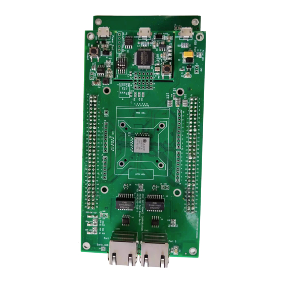
Reference Design User Guide 3-1 AX58200-TSB AX58200-TSB is a test / evaluation board for AX58200 IC and has below components: AX58200 – An ASIX IC that integrated an ESC (EtherCAT Slave Controller) + an ARM cortex-M4 ⚫ ⚫ ESC Port0 – Port0 of the ESC ⚫... -
Page 11: Ax58200-Exb-Adio
AX58200 GPIO / AIO User Guide 3-2 AX58200-EXB-ADIO Reference Design User Guide AX58200-EXB-ADIO is an expansion board for AX58200 GPIO / AIO application and has below components: ⚫ LED for Digital Output – Digital output (8-bit) to the LEDs ⚫... -
Page 12: Basic Operation Of Twincat
Reference Design User Guide Before starting up the AX58200-TSB first time, you MUST download available contents into AX58200 EEPROM first. If there are no available contents in AX58200 EEPROM, the MCU will be reset forcibly by ESC. Assume you already installed the BECKHOFF TwinCAT XAE in your environment. - Page 13 Step 2: Specify “Name” and “Location” and click “OK”. Reference Design User Guide Figure 4 - 3 Step 3: Click the “TWINCAT -> Show Realtime Ethernet Compatible Devices…” ⚫ Figure 4 - 4 Copyright (C) 2019-2020 Reserved by ASIX Electronics Corporation, All Rights Reserved.
- Page 14 Step 5: Please copy the ESI (EtherCAT Slave Information) file “AX58200_GPIO_8Bit_AIO_16bit.xml” from the BSP directory: “YOUR_BSP_FOLDER\SampleCode\Ethercat_GPIO_AIO_Reference_Design\For_ TwinCAT\ESI\” Figure 4 - 6 ⚫ Step 6: Copy the file to TwinCAT directory: “C:\TwinCAT\3.1\Config\Io\EtherCAT\” Figure 4 - 7 Copyright (C) 2019-2020 Reserved by ASIX Electronics Corporation, All Rights Reserved.
- Page 15 Step 7: Click “TWINCAT -> EtherCAT Devices -> Reload Device Descriptions”. Reference Design User Guide Figure 4 - 8 ⚫ Step 8: Plug USB power and connect ESC port0 to TwinCAT master port. Figure 4 - 9 Copyright (C) 2019-2020 Reserved by ASIX Electronics Corporation, All Rights Reserved.
- Page 16 Step 9: Right-click on “IO / Devices” and select “Scan”. Reference Design User Guide Figure 4 - 10 ⚫ Step 10: Choose main network adapter. Figure 4 - 11 ⚫ Step 11: Click “Yes”. Figure 4 - 12 Copyright (C) 2019-2020 Reserved by ASIX Electronics Corporation, All Rights Reserved.
- Page 17 Reference Design User Guide Figure 4 - 13 ⚫ Step 13: Double click “Device N (EtherCAT)” and you will see the TwinCAT master scanned out the EtherCAT slave Figure 4 - 14 Copyright (C) 2019-2020 Reserved by ASIX Electronics Corporation, All Rights Reserved.
- Page 18 Step 14: Select the slave, right-click and choose “EEPROM Update…” Reference Design User Guide Figure 4 - 15 ⚫ Step 15: Select the “AX58200_GPIO_8Bit_AIO_16Bit” and click “OK”. Figure 4 - 16 Copyright (C) 2019-2020 Reserved by ASIX Electronics Corporation, All Rights Reserved.
- Page 19 Step 19: Execute “Scan” again (repeat Step 7 ~ 11) and you will see below screen. ⚫ Assume AX58200 did not download available firmware with Slave Stack Code yet. So the state field “INIT INIT_ERR” is properly / reasonable. Figure 4 - 20...
- Page 20 AX58200 GPIO / AIO User Guide If there is an available firmware with Slave Stack Code in AX58200, you should see below screen. The “State” field is “OP” mode. Reference Design User Guide Figure 4 - 21 Note: Please refer to Chapter 5 for download firmware.
-
Page 21: Download Firmware To Ax58200
GPIO / AIO User Guide 5. Download Firmware to AX58200 Reference Design User Guide If you want to download firmware to AX58200, you have 3 methods basically: (1) Mass Storage Method (MSG mode in ICE) (2) NUVOTON ICP Tool Method... -
Page 22: Mass Storage Method
After finish copy, the AX58200 will auto-restart. Note: If you want to check out the firmware status for judge if the download is success, please refer to Chapter 5.5. Copyright (C) 2019-2020 Reserved by ASIX Electronics Corporation, All Rights Reserved. -
Page 23: Nuvoton Icp Tool Method
Make sure to take off the USB power cable and modify the “DIP of ICE” to below state: Figure 5 - 4 And let “Debug Port” to connect your host as following: Figure 5 - 5 Copyright (C) 2019-2020 Reserved by ASIX Electronics Corporation, All Rights Reserved. - Page 24 AX58200 GPIO / AIO User Guide Execute the ICP Programming Tool. Click “Continue>>”. Reference Design User Guide Figure 5 - 6 Click “Connect” button. Figure 5 - 7 Copyright (C) 2019-2020 Reserved by ASIX Electronics Corporation, All Rights Reserved.
- Page 25 AX58200 GPIO / AIO User Guide If the green text appears, that means the ICP tool finds out the ICE and AX58200 successfully. Reference Design User Guide Figure 5 - 8 Click “APROM” button and select the firmware file “AX58200_GpioAio_vX.X.X.bin” from the BSP directory “YOUR_BSP_FOLDER\SampleCode\EtherCAT_GPIO_AIO_Reference_Design\Binary\”...
- Page 26 AX58200 GPIO / AIO User Guide Click “Options”. Reference Design User Guide Figure 5 - 10 Check the items “Erase”, “Program” and “Verify”. Figure 5 - 11 Copyright (C) 2019-2020 Reserved by ASIX Electronics Corporation, All Rights Reserved.
- Page 27 Reference Design User Guide Figure 5 - 12 Note: If you want to check out the firmware status for judge if the download is success, please refer to Chapter 5.5. Copyright (C) 2019-2020 Reserved by ASIX Electronics Corporation, All Rights Reserved.
-
Page 28: Arm Keil Mdk Method
⚫ Licensed ARM KEIL MDK ⚫ BECKHOFF SSC (Slave Stack Code) or SSC Tool Note: Please refer to the “AX58200 SSC Tool Configuration Import User Guide” for generate related source files. We don’t overtalk the ARM KEIL MDK installation here. We assume it is ready in your environment. Before opening the KEIL project file you must generate related source files through BECKHOFF SSC Tool. - Page 29 Reference Design User Guide Figure 5 - 15 You will see below screen and items: (1) BECKHOFF SSC files and related source files of AX58200 (2) Main program file of Ethercat_GPIO_AIO_Reference_Design (3) The button named “Rebuild” for rebuild all target files (4) The button named “LOAD”...
- Page 30 The output binary file “AX58200_GpioAio.bin” in the directory “YOUR_BSP_FOLDER\SampleCode\Ethercat_GPIO_AIO_Reference_Design\Keil\Objects” Figure 5 - 17 Now you can download the firmware by click “LOAD” button. If the progress complete, the AX58200 will auto- restart. Figure 5 - 18 Copyright (C) 2019-2020 Reserved by ASIX Electronics Corporation, All Rights Reserved.
-
Page 31: Iar Ewarm Method
⚫ Licensed IAR EWARM ⚫ BECKHOFF SSC (Slave Stack Code) or SSC Tool Note: Please refer to the “AX58200 SSC Tool Configuration Import User Guide” for generate related source files. We don’t overtalk the IAR EWARM installation here. We assume it is ready in your environment. Before opening the KEIL project file you must generate related source files through BECKHOFF SSC Tool. - Page 32 (2) Main program file of Ethercat_GPIO_AIO_Reference_Design (3) The button named “Rebuild All” for rebuild all target files (4) The button named “Download active application” for download firmware into AX58200 Figure 5 - 21 The KEIL and IAR project reference the same source codes so the basic definition please refer to abved chapter of KEIL.
-
Page 33: Check Firmware Status By Debug Port
Make sure to take off the USB power cable and modify the “DIP of ICE” to below state: Figure 5 - 22 And let “Debug Port” to connect your host: Figure 5 - 23 Copyright (C) 2019-2020 Reserved by ASIX Electronics Corporation, All Rights Reserved. - Page 34 AX58200 GPIO / AIO User Guide The default setting of UART port of AX58200 as following: Baud rate: 115200 Data: 8 bit Reference Design User Guide Parity: none Stop: 1 bit Flow control: none Figure 5 - 24 Open the COM port. If no any characters appear in COM port, you can press “Reset” button to confirm again.
-
Page 35: Plc Application
PLC entry of TwinCAT project. Please refer to below steps: ⚫ Step 1: Right-click on “PLC” entry and select “Add Existing Item…” Figure 6 - 2 Copyright (C) 2019-2020 Reserved by ASIX Electronics Corporation, All Rights Reserved. - Page 36 Step 2: Select the file “AX58200GpioAio_vX_X_X.tpzip” in your BSP directory “YOUR_BSP_FOLDER\SampleCode\Ethercat_GPIO_AIO_Reference_Design\For_TwinCAT\”. Reference Design User Guide Figure 6 - 3 And you will see below screen, the demo application be inserted into PLC entry. Figure 6 - 4 Copyright (C) 2019-2020 Reserved by ASIX Electronics Corporation, All Rights Reserved.
- Page 37 Step 3: Right-click on “SYSTEM -> Tasks” and select “Add New Item…” Reference Design User Guide Figure 6 - 5 ⚫ Step 4: Type “Plc Task” on “Name” field and click “OK”. Figure 6 - 6 Copyright (C) 2019-2020 Reserved by ASIX Electronics Corporation, All Rights Reserved.
- Page 38 Step 5: Click “AX58200GpioAio Project -> Add -> Referenced Task…” Reference Design User Guide Figure 6 - 7 ⚫ Step 6: Select the “Plc Task” and click “Open”. Figure 6 - 8 Copyright (C) 2019-2020 Reserved by ASIX Electronics Corporation, All Rights Reserved.
- Page 39 Step 7: Right-click on “AX58200GpioAio Project -> Plc_Task -> Add” and select “Existing Item…” Reference Design User Guide Figure 6 - 9 ⚫ Step 8: Select the “AX58200GpioAio -> POUs -> MAIN” and click “OK”. Figure 6 - 10 Copyright (C) 2019-2020 Reserved by ASIX Electronics Corporation, All Rights Reserved.
- Page 40 Yellow color indicates the software variables are used for read PD (Process Data) input value from slave. Red color indicates the software variables are used for write PD (Process Data) output value to slave. Figure 6 - 12 Copyright (C) 2019-2020 Reserved by ASIX Electronics Corporation, All Rights Reserved.
-
Page 41: Pd Link
⚫ Step 1: Right-click on specific software variable and select “Change Link…” Figure 6 - 13 ⚫ Step 2: Select specific PD and click “OK” Figure 6 - 14 Copyright (C) 2019-2020 Reserved by ASIX Electronics Corporation, All Rights Reserved. - Page 42 If you want to check out linked PD, just right click on the software variable and select “Goto Link Variable”. If you want to check out linked software variable while mouse focus the PD, just do same above motion. Figure 6 - 16 Copyright (C) 2019-2020 Reserved by ASIX Electronics Corporation, All Rights Reserved.
-
Page 43: Link Reference
PD link for digital output in 8bit. MAIN.ioAnalogInput16Bit InputWord PD link for analog input in 16bit. MAIN.ioAnalogOutput16Bit OutputWord PD link for analog output in 16bit. Table 6 - 1 Copyright (C) 2019-2020 Reserved by ASIX Electronics Corporation, All Rights Reserved. -
Page 44: Execution Plc
Please follow below steps for execute PLC application: Step 1: Confirm the AX58200 in “OP” state ⚫ Figure 6 - 19 ⚫ Step 2: Click “Login” Figure 6 - 20 Copyright (C) 2019-2020 Reserved by ASIX Electronics Corporation, All Rights Reserved. - Page 45 AX58200 GPIO / AIO User Guide ⚫ Step 3: Click “Yes” Reference Design User Guide Figure 6 - 21 ⚫ Step 4: Click ”Start” icon Figure 6 - 22 Copyright (C) 2019-2020 Reserved by ASIX Electronics Corporation, All Rights Reserved.
- Page 46 Highlight 4: Hex value indicates analog input from “ADC” voltage of EXB-ADIO board. Highlight 5: Input hex value here for control analog output to “DAC” voltage of EXB-ADIO board. Note: Both the ADC and DAC of AX58200 are 12bit accuracy although they declare 16bit in PD. Figure 6 - 24...
-
Page 47: Adc / Dac Description
7. ADC / DAC Description Reference Design User Guide AX58200 has ADC / DAC in 12bit accuracy. This application demonstrates them through AX58200-EXB- ADIO board. If you want to observe or measure voltage of ADC / DAC, please refer to below figure: Figure 7 - 1 You can adjust the “Variable Resistance”... -
Page 48: Switch Id Description
Figure 8 - 1 This setting will let TwinCAT master turn on the identification function for the slave. Select the slave, right-click and select “Advanced Settings…”. Figure 8 - 2 Copyright (C) 2019-2020 Reserved by ASIX Electronics Corporation, All Rights Reserved. - Page 49 Confirm current identification ADO (Address Offset) is “(ADO 0x0134)”. Don’t forget to assign the value in decimal. The value “55” is just an example here. Figure 8 - 4 Copyright (C) 2019-2020 Reserved by ASIX Electronics Corporation, All Rights Reserved.
- Page 50 AX58200 GPIO / AIO User Guide Of course, you should also setup the same value on AX58200-EXB-ADIO board like following: The digit format “Rotary Dip Switch” is hex so that we should set it to “0x37”. Reference Design User Guide Figure 8 - 5 Please note, align the triangle arrow with the number.
- Page 51 If you see the below screen, that means that TwinCAT master already enter running mode successfully and the slave also passed the identification checking so that it can enter OP state. Figure 8 - 9 Copyright (C) 2019-2020 Reserved by ASIX Electronics Corporation, All Rights Reserved.
- Page 52 Click “Device N (EtherCAT) -> Append EtherCAT Cmd”. Figure 8 - 10 Please assign “Command” and “Type”. I demonstrate “FPRD” and “UINT” in this example. Figure 8 - 11 Copyright (C) 2019-2020 Reserved by ASIX Electronics Corporation, All Rights Reserved.
- Page 53 I setup slave address = 0x37 and address offset = 0x12 in this example. Reference Design User Guide Figure 8 - 12 Re-activate the TwinCAT master again. Figure 8 - 13 Copyright (C) 2019-2020 Reserved by ASIX Electronics Corporation, All Rights Reserved.
- Page 54 If you expect that the slave can also use this Switch ID value as second slave address. You just turn on “Seconds address” bit (bit8 = 1) in ESC register 0x0102 (don’t forget click “Write” button). Figure 8 - 15 Copyright (C) 2019-2020 Reserved by ASIX Electronics Corporation, All Rights Reserved.
- Page 55 Click “Device N (EtherCAT) -> Cmd 1 -> DATA”, you will see the command get the value of ESC register 0x0012 back successfully. It is correct, the “0x0037” in UINT data type. Reference Design User Guide Figure 8 - 16 Copyright (C) 2019-2020 Reserved by ASIX Electronics Corporation, All Rights Reserved.
-
Page 56: Firmware Upgrade Through Ethercat Foe
LDROM. The LDROM code helps to validate the FoE firmware, move it to CURRENT RUN TIME area and switch to the area to start the run time firmware again. If your AX58200 platform did not have LDROM code in the flash, please burn it through ICP tool as following: Figure 9 - 2... - Page 57 Restart the AX58200 platform and connect it to TwinCAT master. If everything is OK, you will see the AX58200 in OP mode. Figure 9 - 3 Right-click the AX58200, click the “Firmware Upgrade” and select the firmware file from BSP directory “YOUR_BSP_FOLDER\SampleCode\Etherca_GPIO_AIO_Reference_Design\Keil\Foe\AX58200_Gpio_ai o.efw” or “YOUR_BSP_FOLDER\SampleCode\Etherca_GPIO_AIO_Reference_Design\IAR\Foe\AX58200_Gpio_ai...
- Page 58 TwinCAT master will notice user the function successes, just click “OK”. Due to the AX58200 will restart the system after firmware upgrading so that TwinCAT will indicate the slave not in the expected state. Don’t worry, this is a normal situation. TwinCAT will try to switch the slave to original state (ex: OP or BOOTSTRAP).
-
Page 59: Shortest Ethercat Cycle Evaluation
GPIO / AIO User Guide 10. Shortest EtherCAT Cycle Evaluation Reference Design User Guide We tried to decrease the TwinCAT cycle to evaluate shortest cycle of AX58200 GPIO / AIO. “100us” Shortest workable cycle of AX58200 GPIO / AIO is now. - Page 60 The slave stack also does not indicate any errors in SM output parameter / SM input parameter objects of CoE-Online table. Reference Design User Guide Figure 10 - 3 Copyright (C) 2019-2020 Reserved by ASIX Electronics Corporation, All Rights Reserved.
- Page 61 No part of this document may be reproduced or transmitted in any form or by any means, electronic or mechanical, including photocopying and recording, for any purpose, without the express written permission of ASIX. ASIX may make changes to the product specifications and descriptions in this document at any time, without notice.
- Page 62 AX58200 GPIO / AIO User Guide Reference Design User Guide 4F, No.8, Hsin Ann Rd., Hsinchu Science Park, Hsinchu, Taiwan, R.O.C. TEL: +886-3-5799500 FAX: +886-3-5799558 Email: support@asix.com.tw Web: http://www.asix.com.tw Copyright (C) 2019-2020 Reserved by ASIX Electronics Corporation, All Rights Reserved.
Need help?
Do you have a question about the AX58200 and is the answer not in the manual?
Questions and answers