Table of Contents
Advertisement
Quick Links
Advertisement
Table of Contents

Subscribe to Our Youtube Channel
Related Manuals for ASIX AX58200


Summary of Contents for ASIX AX58200
- Page 1 Motor Control User Guide Reference Design User Guide AX58200 Motor Control User Guide Revision 2.00 Oct.20 , 2021 rch 14 , 2020 rch 14 , 2020 rch 14 , 2020 Copyright (C) 2020-2021 Reserved by ASIX Electronics Corporation, All Rights Reserved.
- Page 2 Motor Control User Guide Revision History Reference Design User Guide Revision Date Description 1.00 2020/03/27 Initial release 2.00 2021/10/20 Modified the control mode to FOC and three-loop PI controller Copyright (C) 2020-2021 Reserved by ASIX Electronics Corporation, All Rights Reserved.
-
Page 3: Table Of Contents
7-4 Set DC Cycle Time ________________________________________________________________ 59 7-5 Execution PLC ___________________________________________________________________ 62 8. Object Dictionary ____________________________________________________________ 67 8-1 Objects Description _______________________________________________________________ 67 9. Performance Evaluation _______________________________________________________ 69 9-1 Minimum DC Cycle Time __________________________________________________________ 69 Copyright (C) 2020-2021 Reserved by ASIX Electronics Corporation, All Rights Reserved. - Page 4 Figure 6 - 10 ..................................31 Figure 6 - 11 ..................................31 Figure 6 - 12 ..................................32 Figure 6 - 13 ..................................33 Figure 6 - 14 ..................................33 Copyright (C) 2020-2021 Reserved by ASIX Electronics Corporation, All Rights Reserved.
- Page 5 Figure 7 - 13 ..................................58 Figure 7 - 14 ..................................59 Figure 7 - 15 ..................................59 Figure 7 - 16 ..................................60 Figure 7 - 17 ..................................60 Copyright (C) 2020-2021 Reserved by ASIX Electronics Corporation, All Rights Reserved.
- Page 6 Figure 7 - 31 ..................................65 Figure 7 - 32 ..................................66 Figure 9 - 1 ..................................69 Figure 9 - 2 ..................................69 Figure 9 - 3 ..................................70 Copyright (C) 2020-2021 Reserved by ASIX Electronics Corporation, All Rights Reserved.
- Page 7 Table 4 - 1 ................................... 17 Table 7 - 1 ................................... 59 Table 8 - 1 ................................... 67 Table 8 - 2 ................................... 68 Table 8 - 3 ................................... 68 Copyright (C) 2020-2021 Reserved by ASIX Electronics Corporation, All Rights Reserved.
-
Page 8: Introduction
1. Introduction Reference Design User Guide This document introduces how to setup entire environment for motor control application on AX58200 evaluation platform (TSB + EXB-SDB boards). The demo application of EtherCAT master side develops by PLC (Programmable Logic Controller) language through BECKHOFF TwinCAT engineering (XAE). The IDE rely Microsoft Visual Studio 2010 / 2013. -
Page 9: Introduce Block Diagram Of System
The following figure is a simple servo drive block diagram. The software used on the PC side is “TwinCAT Reference Design User Guide XAE”. The communication connection method is to connect to the AX58200-TSB through a network cable. In terms of usage, TwinCAT XAE is biased towards demonstration. -
Page 10: Requirements
[Software at EtherCAT slave side] ⚫ ARM KEIL MDK micro-Vision 5 (for development only) Figure 2 - 2 ⚫ IAR Embedded Workbench for ARM 7.40 (for development only) Figure 2 - 3 Copyright (C) 2020-2021 Reserved by ASIX Electronics Corporation, All Rights Reserved. - Page 11 AX58200 Motor Control User Guide [Hardware] ⚫ AX58200 Test Board (AX58200-TSB) x 1 Reference Design User Guide Figure 2 - 4 Figure 2 - 5 Copyright (C) 2020-2021 Reserved by ASIX Electronics Corporation, All Rights Reserved.
- Page 12 AX58200 Motor Control User Guide ⚫ AX58200-EXB-SDB-1 3-Phase Inverter Board x 1 Reference Design User Guide Figure 2 - 6 Figure 2 - 7 Copyright (C) 2020-2021 Reserved by ASIX Electronics Corporation, All Rights Reserved.
- Page 13 ⚫ MOTION TECH BL60M24D8E00430080 Motor x 1 Please refer to MTM official website for more detail: http://www.motiontech.com.tw/ Reference Design User Guide Figure 2 - 8 Table 2 - 1 Copyright (C) 2020-2021 Reserved by ASIX Electronics Corporation, All Rights Reserved.
- Page 14 AX58200 Motor Control User Guide Reference Design User Guide Table 2 - 2 Table 2 - 3 ⚫ 24VDC/8A Power Supply x 1 Figure 2 - 9 Copyright (C) 2020-2021 Reserved by ASIX Electronics Corporation, All Rights Reserved.
-
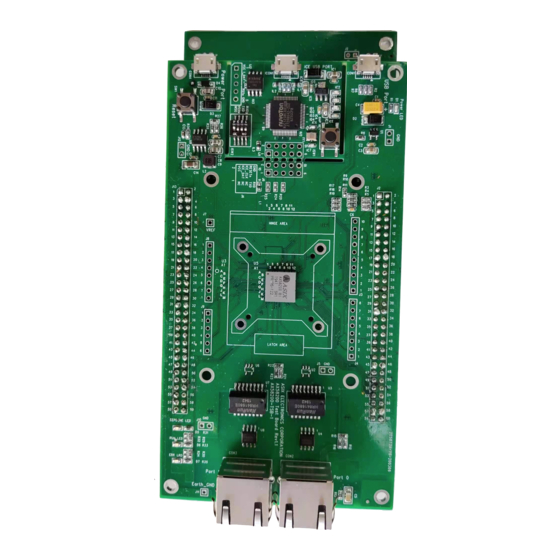
Page 15: Board Description
3-1 AX58200-TSB-1 Rev3.0 AX58200-TSB is a test / evaluation board for AX58200 IC and has below components: ⚫ AX58200 – An ASIX IC that integrated an ESC (EtherCAT Slave Controller) + an ARM cortex-M4 ⚫ ESC Port0 – Port0 of the ESC ⚫... -
Page 16: Ax58200-Exb-Sdb-1 Rev1.0
AX58200 Motor Control User Guide 3-2. AX58200-EXB-SDB-1 Rev1.0 Reference Design User Guide The AX58200-EXB-SDB-1 Rev1.0 is a three-phase brushless DC motor driver expansion board and has below components: ⚫ J1 – Hall components power input connector. ⚫ J2 – Hall components phase-U phase-V phase-W input connector. -
Page 17: Hardware Setup
Please based on below table to connect all necessary equipment. Table 4 - 1 Then you can get the final slave side environment as following. Figure 4 - 1 Copyright (C) 2020-2021 Reserved by ASIX Electronics Corporation, All Rights Reserved. -
Page 18: Basic Operation Of Twincat
Reference Design User Guide Before starting up the AX58200-TSB first time, you must download available contents into AX58200 EEPROM first. If there are no available contents in AX58200 EEPROM, the MCU will be reset forcibly by ESC. Assume you already installed the BECKHOFF TwinCAT XAE in your environment. - Page 19 Step 2: Specify “Name” and “Location” and click “OK”. Reference Design User Guide Figure 5 - 3 ⚫ Step 3: Click the “TWINCAT -> Show Realtime Ethernet Compatible Devices…” Figure 5 - 4 Copyright (C) 2020-2021 Reserved by ASIX Electronics Corporation, All Rights Reserved.
- Page 20 BSP directory: “YOUR_BSP_FOLDER\SampleCode\Ethercat_MotorControl_Reference_Design\For_Twi nCAT\ESI\” ⚫ Step 6: Copy the file to TwinCAT directory: “C:\TwinCAT\3.1\Config\Io\EtherCAT\” ⚫ Step 7: Click “TWINCAT -> EtherCAT Devices -> Reload Device Descriptions”. Figure 5 - 6 Copyright (C) 2020-2021 Reserved by ASIX Electronics Corporation, All Rights Reserved.
- Page 21 Step 8: Plug USB power and connect ESC port0 to TwinCAT master port. Reference Design User Guide Figure 5 - 7 ⚫ Step 9: Right-click on “IO / Devices” and select “Scan”. Figure 5 - 8 Copyright (C) 2020-2021 Reserved by ASIX Electronics Corporation, All Rights Reserved.
- Page 22 Step 10: Choose main network adapter and click “OK”. Reference Design User Guide Figure 5 - 9 ⚫ Step 11: Click “Yes”. Figure 5 - 10 ⚫ Step 12: Click “Yes”. Figure 5 - 11 Copyright (C) 2020-2021 Reserved by ASIX Electronics Corporation, All Rights Reserved.
- Page 23 Step 13: Double click “Device N (EtherCAT)” and you will see the TwinCAT master scanned out the EtherCAT slave Reference Design User Guide Figure 5 - 12 ⚫ Step 14: Select the slave, right-click and choose “EEPROM Update…” Figure 5 - 13 Copyright (C) 2020-2021 Reserved by ASIX Electronics Corporation, All Rights Reserved.
- Page 24 Step 16: Wait for progress bar at lower right corner of the TwinCAT screen. Figure 5 - 15 ⚫ Step 17: Select “Device N (EtherCAT)”, right-click and choose “Remove”. Figure 5 - 16 Copyright (C) 2020-2021 Reserved by ASIX Electronics Corporation, All Rights Reserved.
- Page 25 So, the state field “INIT INIT_ERR” is properly / reasonable. Figure 5 - 18 If there is an available firmware with Slave Stack Code in AX58200, you should see below screen. The “State” field is “OP” mode. Figure 5 - 19 Note: Please refer to Chapter 6 for download firmware.
-
Page 26: Download Firmware/Parameter To Ax58200
Reference Design User Guide This chapter will be divided into the following sections. Sections 6-1~6-5 introduce 5 ways to download firmware. Section 6-6 introduces downloading parameter files to AX58200 IC. The last section Introduce firmware status by debug port. The following are 5 methods to download firmware, which are introduced in sections 6-1 ~ 6-5:... -
Page 27: Mass Storage Method
(for example: “F:\”). After finish copy, the AX58200 will auto-restart. Note: If you want to check out the firmware status for judge if the download is success, please refer to section Copyright (C) 2020-2021 Reserved by ASIX Electronics Corporation, All Rights Reserved. -
Page 28: Nuvoton Icp Tool Method
Make sure to take off the USB power cable and modify the “DIP of ICE” to below state: Figure 6 - 4 And let “Debug Port” to connect your host as following: Figure 6 - 5 Copyright (C) 2020-2021 Reserved by ASIX Electronics Corporation, All Rights Reserved. - Page 29 AX58200 Motor Control User Guide Execute the ICP Programming Tool. Click “Continue>>”. Reference Design User Guide Figure 6 - 6 Click “Connect” button. Figure 6 - 7 Copyright (C) 2020-2021 Reserved by ASIX Electronics Corporation, All Rights Reserved.
- Page 30 AX58200 Motor Control User Guide If the green text appears, that means the ICP tool finds out the ICE and AX58200 successfully. Reference Design User Guide Figure 6 - 8 Click “APROM” button and select the firmware file “AX58200_MotorControl_vX.X.X.bin” from the BSP directory “YOUR_BSP_FOLDER\SampleCode\Ethercat_MotorControl_Reference_Design\Binary\”...
- Page 31 AX58200 Motor Control User Guide Click “Options”. Reference Design User Guide Figure 6 - 10 Check the items “Erase”, “Program” and “Verify”. Figure 6 - 11 Copyright (C) 2020-2021 Reserved by ASIX Electronics Corporation, All Rights Reserved.
- Page 32 Reference Design User Guide Figure 6 - 12 Note: If you want to check out the firmware status for judge if the download is success, please refer to section 6-7. Copyright (C) 2020-2021 Reserved by ASIX Electronics Corporation, All Rights Reserved.
-
Page 33: Arm Keil Mdk Method
Make sure to take off the USB power cable and modify the “DIP of ICE” to below state: Figure 6 - 13 And let “Debug Port” to connect your host: Figure 6 - 14 Copyright (C) 2020-2021 Reserved by ASIX Electronics Corporation, All Rights Reserved. -
Page 34: Use Beckhoff Ssc Tool To Generate Ethercat Slave Stack Code
Step 1: First, enter the following directory and execute "AX58200_MotorControl.esp": “YOUR_BSP_FOLDER\SampleCode\Ethercat_MotorControl_Reference_Design\For_SSC_Tool\ ”. Figure 6 - 15 ⚫ Step 2: Click menu “File -> New” to create new project. Figure 6 - 16 Copyright (C) 2020-2021 Reserved by ASIX Electronics Corporation, All Rights Reserved. - Page 35 Step 3: Import Configuration file by click “Import” button. Reference Design User Guide Figure 6 - 17 ⚫ Step 4: Select “AX58200_MotorControlConfigurations.xml” from directory and click “Open”. “YOUR_BSP_FOLDER\SampleCode\Ethercat_MotorControl_Reference_Design\For_SSC_Tool\I mport\Configuration\”. Figure 6 - 18 Copyright (C) 2020-2021 Reserved by ASIX Electronics Corporation, All Rights Reserved.
- Page 36 AX58200 Motor Control User Guide ⚫ Step 5: Click “OK”. Reference Design User Guide Figure 6 - 19 ⚫ Step 6: Click “Yes”. Figure 6 - 20 Copyright (C) 2020-2021 Reserved by ASIX Electronics Corporation, All Rights Reserved.
- Page 37 Step 7: Select “Import” for import object dictionary. Reference Design User Guide Figure 6 - 21 ⚫ Step 8: Select “AX58200_MotorControl.xlsx” from directory and click “Open” “YOUR_BSP_FOLDER\SampleCode\Ethercat_MotorControl_Reference_Design\For_SSC_Tool\ Import\Configuration\files\”. Figure 6 - 22 Copyright (C) 2020-2021 Reserved by ASIX Electronics Corporation, All Rights Reserved.
- Page 38 Step 9: You can see the screen show the “Check objects finished” and click “OK”. Reference Design User Guide Figure 6 - 23 ⚫ Step 10: Select “Create new Slave Files”. Figure 6 - 24 Copyright (C) 2020-2021 Reserved by ASIX Electronics Corporation, All Rights Reserved.
- Page 39 Figure 6 - 25 ⚫ Step 12: You must first save the file to the following directory: “YOUR_BSP_FOLDER\SampleCode\Ethercat_MotorControl_Reference_Design\For_SSC_Tool\ ”. Figure 6 - 26 ⚫ Step 13: Click “Yes”. Figure 6 - 27 Copyright (C) 2020-2021 Reserved by ASIX Electronics Corporation, All Rights Reserved.
- Page 40 Reference Design User Guide Src\”. The “ESI File” must be saving in the directory: “YOUR_BSP_FOLDER\SampleCode\Ethercat_MotorControl_Reference_Design\For_SSC_Tool\ ”. Figure 6 - 28 ⚫ Step 15: Click “OK”. Figure 6 - 29 Copyright (C) 2020-2021 Reserved by ASIX Electronics Corporation, All Rights Reserved.
- Page 41 Step 16: You can see the “Create Slave files finished” and click “Close”. Final, confirm that the source code exists in the following directory: “YOUR_BSP_FOLDER\SampleCode\Ethercat_MotorControl_Reference_Design\For_SSC_Tool\ Reference Design User Guide Src\”. Figure 6 - 30 Figure 6 - 31 Copyright (C) 2020-2021 Reserved by ASIX Electronics Corporation, All Rights Reserved.
-
Page 42: Use Arm Keil Mdk Download Firmware
If everything is fine, you should see Build Output window without errors after click “Build” button. The output binary file “AX58200_MotorControl.bin” in the directory “YOUR_BSP_FOLDER\SampleCode\Ethercat_MotorControl_Reference_Design\Keil\Objects\” Now you can download the firmware by click “Download” button. If the progress complete, the AX58200 will auto-restart. Copyright (C) 2020-2021 Reserved by ASIX Electronics Corporation, All Rights Reserved. -
Page 43: Iar Ewarm Method
Then open the IAR project by double-click the project file “MotorControl.eww” in the directory. “YOUR_BSP_FOLDER\SampleCode\Ethercat_MotorControl_Reference_Design\IAR\”. You will see below screen and items: (1) BECKHOFF SSC files and related source files of AX58200 (2) Motor control stack code (3) Main program file of Motor Control Reference Design (4) Click on menu “Project/Rebuild All”... -
Page 44: Firmware Upgrading By Twincat Foe
You must open TwinCAT first, please refer to the instructions of steps 1~12 in Chapter 5-2, and then please refer to the following steps for firmware upgrade. ⚫ Step 1: Right-click the “Box 1” and select the “Firmware update”. Figure 6 - 35 Copyright (C) 2020-2021 Reserved by ASIX Electronics Corporation, All Rights Reserved. - Page 45 ⚫ Step 3: Click the “OK”. Figure 6 - 37 ⚫ Step 4: Wait for progress bar at lower right corner of the TwinCAT screen. Figure 6 - 38 Copyright (C) 2020-2021 Reserved by ASIX Electronics Corporation, All Rights Reserved.
- Page 46 Reference Design User Guide Figure 6 - 39 Note: If you want to check out the firmware status for judge if the download is success, please refer to section 6-7. Copyright (C) 2020-2021 Reserved by ASIX Electronics Corporation, All Rights Reserved.
-
Page 47: Servo Parameter Upgrading By Twincat Foe
The following steps are the same as section 6-5 TwinCAT Firmware Upgrade. Only the selected file is a parameter file, please refer to the following steps to perform parameter upgrade. Step 1: Right-click the “Box 1” and select the “Firmware update”. Figure 6 - 41 Copyright (C) 2020-2021 Reserved by ASIX Electronics Corporation, All Rights Reserved. - Page 48 Step 3: Click the “OK”. ⚫ Figure 6 - 43 ⚫ Step 4: Wait for progress bar at lower right corner of the TwinCAT screen. Figure 6 - 44 Copyright (C) 2020-2021 Reserved by ASIX Electronics Corporation, All Rights Reserved.
- Page 49 Reference Design User Guide Figure 6 - 45 Note: If you want to check out the firmware status for judge if the download is success, please refer to section 6-7. Copyright (C) 2020-2021 Reserved by ASIX Electronics Corporation, All Rights Reserved.
-
Page 50: Servo Parameter File Generation For Twincat Foe
32bytes file information, nothing else has changed. the 32 bytes file information is used to do file signature, data integrity check and file type distinguish. ⚫ AX58200_BL60M24D8E00430080_MTMBL60.efw Similar to AX58200_MotorControl.efw, but is converted from BL60M24D8E00430080_MTMBL60.txt and used for servo parameter upgrading. Copyright (C) 2020-2021 Reserved by ASIX Electronics Corporation, All Rights Reserved. -
Page 51: Check Firmware Status By Debug Port
Make sure to take off the USB power cable and modify the “DIP of ICE” to below state: Figure 6 - 48 And let “Debug Port” to connect your host: Figure 6 - 49 Copyright (C) 2020-2021 Reserved by ASIX Electronics Corporation, All Rights Reserved. - Page 52 Motor Control User Guide You can check the success of the firmware and parameter upgrade through the Serial port tool. The following example uses “Tera Term” as the serial port tool, and default setting of UART port of AX58200 Reference Design User Guide as following: ⚫...
-
Page 53: Plc Application
PLC entry of TwinCAT project. Please refer to below steps: ⚫ Step 1: Right-click on “PLC” entry and select “Add Existing Item…”. Figure 7 - 2 Copyright (C) 2020-2021 Reserved by ASIX Electronics Corporation, All Rights Reserved. - Page 54 And you will see below screen, the demo application be inserted into PLC entry. Figure 7 - 3 ⚫ Step 3: Right-click on “AX58200_MotorControl_v_x_x_x Project” and select “Build”. Figure 7 - 4 Copyright (C) 2020-2021 Reserved by ASIX Electronics Corporation, All Rights Reserved.
-
Page 55: Pd Link
We illustrate procedure of PD link here. If you want to create a PD link, please follow below procedure: ⚫ Please follow steps below then press “OK” to complete PD link of “MAIN.arrAms_NetId” variable. Figure 7 - 6 Copyright (C) 2020-2021 Reserved by ASIX Electronics Corporation, All Rights Reserved. - Page 56 Figure 7 - 7 ⚫ Next, you need to complete remaining PD link in the same way. Link “Golbal_Value_Axes[0].nStateWord” variable. Figure 7 - 8 Link “Golbal_Value_Axes[0].nPosActVal” variable. Figure 7 - 9 Copyright (C) 2020-2021 Reserved by ASIX Electronics Corporation, All Rights Reserved.
- Page 57 AX58200 Motor Control User Guide Link “Golbal_Value_Axes[0].nCtrlWord” variable. Reference Design User Guide Figure 7 - 10 Link “Golbal_Value_Axes[0].nTargetPos” variable. Figure 7 - 11 Copyright (C) 2020-2021 Reserved by ASIX Electronics Corporation, All Rights Reserved.
- Page 58 Reference Design User Guide Figure 7 - 12 If you want to clear the link, just right click on the software or PD and select “Clear Link(s)”. Figure 7 - 13 Copyright (C) 2020-2021 Reserved by ASIX Electronics Corporation, All Rights Reserved.
-
Page 59: Link Reference
Step 1: Double click Real Time and set Real Time 1ms (the shortest task cycle time 1ms) Figure 7 - 14 ⚫ Step 2: Click “I/O Idle Task” and set “Cycle ticks” a 1ms Figure 7 - 15 Copyright (C) 2020-2021 Reserved by ASIX Electronics Corporation, All Rights Reserved. - Page 60 Step 4: Double click “Device N (EtherCAT)” and click “Advanced Settings…”. Figure 7 - 17 ⚫ Step 5: Click “Distributed Clocks” and select “DC in use”. Figure 7 - 18 Copyright (C) 2020-2021 Reserved by ASIX Electronics Corporation, All Rights Reserved.
- Page 61 Step 6: Click “Box 1”, enter the DC tab, and click “Advanced Settings…”. Reference Design User Guide Figure 7 - 19 ⚫ Step 7: Select “DC-Synchron”, click “Use as potential Reference Clock”, and click “OK”. Figure 7 - 20 Copyright (C) 2020-2021 Reserved by ASIX Electronics Corporation, All Rights Reserved.
-
Page 62: Execution Plc
Please follow below steps for running mode and then execute PLC application: ⚫ Step 1: Click “Activate Configuration”. Figure 7 - 21 ⚫ Step 2: Click “OK”. Figure 7 - 22 ⚫ Step 3: Click “OK”. Figure 7 - 23 Copyright (C) 2020-2021 Reserved by ASIX Electronics Corporation, All Rights Reserved. - Page 63 Reference Design User Guide Figure 7 - 24 ⚫ Step 5: Confirm the AX58200 is in “OP” state. Figure 7 - 25 ⚫ Step 6: Click “Login”. Figure 7 - 26 Copyright (C) 2020-2021 Reserved by ASIX Electronics Corporation, All Rights Reserved.
- Page 64 Reference Design User Guide Figure 7 - 27 ⚫ Step 8: Click “Start”. Figure 7 - 28 ⚫ Step 9: Double click “Demonstration” to open PLC GUI. Figure 7 - 29 Copyright (C) 2020-2021 Reserved by ASIX Electronics Corporation, All Rights Reserved.
- Page 65 AX58200 Motor Control User Guide ⚫ Step 10: Power On Reference Design User Guide Figure 7 - 30 ⚫ Step 11: Run Demonstration Figure 7 - 31 Copyright (C) 2020-2021 Reserved by ASIX Electronics Corporation, All Rights Reserved.
- Page 66 Reference Design User Guide 3: Power On/Off. 4: Power Lamp. 5: Fault Reset request. 6: Fault Lamp. 7: Offset angle after homing. 8: Homing. 9: Start/Stop Demonstration. Figure 7 - 32 Copyright (C) 2020-2021 Reserved by ASIX Electronics Corporation, All Rights Reserved.
-
Page 67: Object Dictionary
RECORD Tx pdo mapping of csp/csv actual position actual velocity mode of operation display Mapped objects: 0x1A01 PDO Mapping RECORD Tx pdo mapping of csp status word actual position Copyright (C) 2020-2021 Reserved by ASIX Electronics Corporation, All Rights Reserved. - Page 68 Target velocity INTEGER32 0x6502 (CSP、PP、HM mode is Supported drive modes UNSIGNED32 supported in this FW verson) 0xF000 RECORD Modular device profile 0xF010 Module profile list UNSIGNED32 Table 8 - 3 Copyright (C) 2020-2021 Reserved by ASIX Electronics Corporation, All Rights Reserved.
-
Page 69: Performance Evaluation
8bytes input and 8bytes output, under this setting, the minimum DC cycle time can down to 250us. Figure 9 - 1 Without frame lost and Tx/Rx error at Master side. Figure 9 - 2 Copyright (C) 2020-2021 Reserved by ASIX Electronics Corporation, All Rights Reserved. - Page 70 AX58200 Motor Control User Guide Also, without detected SM-Event Missed, Cycle Time Too Small and Sync Error at Slave side. Reference Design User Guide Figure 9 - 3 Copyright (C) 2020-2021 Reserved by ASIX Electronics Corporation, All Rights Reserved.
- Page 71 No part of this document may be reproduced or transmitted in any form or by any means, electronic or mechanical, including photocopying and recording, for any purpose, without the express written permission of ASIX. ASIX may make changes to the product specifications and descriptions in this document at any time, without notice.
- Page 72 AX58200 Motor Control User Guide Reference Design User Guide 4F, No.8, Hsin Ann Rd., Hsinchu Science Park, Hsinchu, Taiwan, R.O.C. TEL: +886-3-5799500 FAX: +886-3-5799558 Email: support@asix.com.tw Web: http://www.asix.com.tw Copyright (C) 2020-2021 Reserved by ASIX Electronics Corporation, All Rights Reserved.
Need help?
Do you have a question about the AX58200 and is the answer not in the manual?
Questions and answers