Table of Contents
Advertisement
Quick Links
Advertisement
Table of Contents

Related Manuals for ASIX PRESTO


Summary of Contents for ASIX PRESTO
- Page 1 PRESTO USB In-System Programmer Reference Manual...
- Page 2 ASIX s.r.o. reserves the right to make changes to this document, the latest version of which can be found on the Internet. ASIX s.r.o. renounces responsibility for any damage caused by the use of ASIX s.r.o. products.
-
Page 3: Table Of Contents
2.6.3 Connecting Procedure Table of Contents 2.6.4 Connection Examples PIC Microcontrollers Introduction AVR Microcontrollers PRESTO AVR with TPI Interface (e.g. ATtiny10) Atmel 8051 2.1 Package Content 2.2 Features Cypress PSoC MSP430 with TEST pin without SBW interface 2.3 Quick Start 2.3.1... - Page 4 3.1.1 Windows Operating Systems 5.4.4 Calibration Memory Support Windows 7 and later Working with Calibration Memory When Erasing a Device in UV Eraser Older supported Windows versions Working With Calibration Memory in Devices With 3.1.2 Linux Flash Memory 5.5 Program Controls 3.2 Driver Updating 5.5.1 Toolbar...
- Page 5 View ➙ Console Device ➙ Select device View ➙ Display code/main memory Options Menu View ➙ Display data memory Options ➙ Program settings ➙ Programming View ➙ Display configuration memory ▸ Reload file before every programming View ➙ Display programmer form ▸...
- Page 6 Help ➙ List of supported devices Options ➙ Program settings ➙ Serial numbers Help ➙ Check Internet for updates ▸ Serial numbers Help ➙ ASIX website ▸ Prepare S/N before programming Help ➙ About ▸ Find successor after programming 5.5.4 Programmer Settings Window ▸...
- Page 7 Settings Associated with SPI Flash Chips File Opening ▸ Start address Device Programming ▸ End address 5.6.2 Program Return Codes PRESTO Programmer Settings Window 5.7 Running UP by Means of Windows In idle state Messages During programming 5.7.1 List of Commands...
- Page 8 7.2.5 RUNTEST with run_count and no timing HVP Algorithm (both SVF and XSVF) LVP algorithm (without VPP) 7.2.6 VPP PRESTO / P FORTE pin usage while running test (file) / after test completion Loading of Different Programmer Pins 7.2.7 Default Settings 5.13.2 Power Supply Options...
-
Page 9: Introduction
(In-Circuit Serial Programming). meaning of ICSP is identical with the This manual describes PRESTO, a USB programmer and meaning of ISP (In System Programming) in its control software, both manufactured by ASIX. this manual, i.e. device programming done inside a system. -
Page 10: Presto
• USB cable (type A - B) Start with installing the UP program. Its installer installs • CD-ROM with manual and drivers the USB driver for PRESTO, too. You can find the installer on the supplied CD-ROM or on the web (the preferred • Info leaflet option). -
Page 11: Linux
2.4.2 USB Connection under Linux in Wine. 2.4.1 Numerous Supported PRESTO is controlled and powered through a USB port. It communicates in the Full-Speed mode and works with a Devices USB 2.0 port or a USB 1.1 port. This means that... -
Page 12: Programming Of Autonomous Devices
UP has been developed for Windows XP or later. It also voltage: 3 V, 5 V and overvoltage. works under Linux (through Wine). PRESTO includes an overcurrent protection at pins P and Modified drivers developed by FTDI are used for VDD. communication through USB. -
Page 13: Debugging
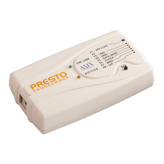
The revision 717 of OpenOCD, which can be found on our website in a program package together with the ARMINE program, is supported officially. Fig.2: The PRESTO programmer PRESTO features two LEDs, a button, a connector for linking to USB and a programming connector. 2.5.1 Programming Connector The programming connector is a 8 way single row plug with pin No. 2 (in standard numbering) missing. -
Page 14: Go Button
2.5.3 LED Indicators ON-LINE The green LED informs you that PRESTO is connected to a computer and that the computer and the programmer “understand each other”, i.e. drivers are installed and work correctly. In Linux, the green LED turns on upon connecting the programmer to a PC even before the driver is correctly installed. -
Page 15: Custom-Made Connecting Cable
Connecting to FCI marking Description 65039-036LF housing, 1 pin Application 65039-029LF housing, 1 x 8 pins 47217-000LF The programmer should be connected to an application to Table 2: ICSP cable - material list be programmed with an ICSPCAB8 which is designed for 2.54 mm spacing. -
Page 16: Connecting Procedure
MOSI The correct procedure for connecting the programmer: first connect PRESTO to the target application, then TPICLK connect PRESTO to the USB and finally turn on the MISO MISO application’s power supply. Please make sure that the GND of the application, the Table 3: Connection list No.1... -
Page 17: Connection Examples
The following text presents examples of connections recommended to limit voltage on the MCLR pin by an between PRESTO and the device being programmed. We external circuit (a potential divider or a Zener diode use a notation according to the manufacturer datasheet and a resistor). -
Page 18: Avr Microcontrollers
1 MHz. In the initial programming, the device should be programmed with “Oscillator frequency” set up at “>750 kHz” or lower in the “PRESTO programmer settings” window. Not all AVR microcontrollers allow use of a crystal (e.g. ATtiny13, ATtiny15). -
Page 19: Avr With Tpi Interface (E.g. Attiny10)
AT89LP213, AT89LP214 and AT89LP216 have the inverse reset logic. Thus an appropriate resistor must be pulled-up to VCC. PRESTO can not program devices containing the letter “C” in their name, however, it supports devices with “S” in their name, of which some are compatible with the “C”... -
Page 20: Msp430 With Test Pin Without Sbw Interface
The way of entering in the programming mode The safety fuse on the JTAG interface cannot be should be set in the PRESTO programmer settings blown by the PRESTO programmer. window. Devices without an XRST pin can only use The HPR3V3 adapter should be used for feeding... -
Page 21: Ti (Chipcon) Ccxxxx
The PRESTO programmer also erases the Segment A of the information memory with the SPI Memory Chips Erase Segment A option selected. TI (Chipcon) CCxxxx <<( ti_chipcon.jpg | 10cm | TI (Chipcon) Ccxxxx microcontroller ) I2C Memory Chips Fig.14: SPI memory chips Some devices have WP, HOLD or RESET pins. -
Page 22: Microwire Memory Chips
8-bits or 16-bits per word. The user selects the open source debugging system originally developed required organization in the UP program and PRESTO by Dominic Rath. OpenOCD uses GDB for access to then sets this pin to the corresponding logic level. If debug functions. -
Page 23: Hpr Adapters
The HPR3V3 level shifter can be used very simply. Plug it levels between 3 and 5 V ± 10%, but sometimes it is directly to the pins of the PRESTO programmer (NOT to necessary to program a device with less signal levels. In the programmed device connector!). -
Page 24: Hpravr Adapter
2.7.3 HPRAVR Adapter the application could be damaged if incorrectly connected. HPRAVR is an optional accessory for PRESTO and FORTE programmers for programming AVR microcontrollers in applications with the ISP10PIN standard connector on the device's side and with the ICSPCAB8 cable on the programmer's side. -
Page 25: Built-In Protection
VPP and VDD pins and overvoltage Maximum current on 20 mA protection on the VDD pin. I/O pin PRESTO is able to detect overcurrent on the VPP or VDD ESD protection (HBM ±4 kV contact pin and consequently to disable these pins but only when model) ±8 kV air... -
Page 26: Declaration Of Conformity
Maximum current drawn from I/ 4 mA 2.9.3 Declaration of O pin Conformity Allowed input voltage on pins 0 to 5.5 V P pin output voltage 13 V or logic levels VIL input voltage max. 0.5 V VIH input voltage min. 2.0 V VOL output voltage max. - Page 27 PRESTO complies with the RoHS directive. Page 27...
-
Page 28: Drivers
UP program installation. Windows 7 and later Start with installing the UP program. Its installer installs the USB driver for PRESTO, too. You can find the installer on the supplied CD-ROM or on the web (the preferred option). Once the installation is complete, connect the PRESTO programmer to your computer. -
Page 29: Linux
The programmer can be operated under Wine in Linux. Please find detailed installation instructions at separate chapter. Driver Updating PRESTO communicates with the PC through a USB circuit produced by FTDI www.ftdichip.com, which also develops drivers for these circuits. The latest drivers are always included in the UP installation pack. -
Page 30: Usage Under Linux
• If you have not access rights and you are using udev: Create a user group (or use in any of the suitable existing groups) which will have access to ASIX USB devices. Usage under Linux Add a new file with udev rules to the directory... - Page 31 Installation of the Microsoft™ TrueType core fonts are recommended. These fonts may be obtained by installing msttcorefonts package from Ubuntu package repository. Note: Library libftd2xx requires also access rights during opening of the programmer or logic analyzer to all FTDI serial devices to check that this is not the device it wants to open.
-
Page 32: Up Software
Device Programming UP is a name for control software designed for programmers made by ASIX. The program offers many The following sections describe the ways of programming advanced functions and enables an operator to control devices and things to pay special attention to. -
Page 33: Projects
This is followed by selecting a device type, a file with programming data, settings of the device's configuration word, applied voltage and other important parameters. configuration word, applied voltage and other important parameters. Once all required selections are made, save the project by choosing File ➙... -
Page 34: Program Settings
5.3.4 Program settings It is advisable to fine-tune the program behavior by adjusting the settings to suit your particular needs. This can be done by choosing Options ➙ Program settings. There is a great number of possible settings. If you are not sure that all the settings are correct, use the Load defaults button, which returns all the setting to the original (default) state. -
Page 35: Production Programming Settings
programming and verification of the whole memory content. The function of this button is programmable and Production Programming can be set up under the Options ➙ Key shortcuts menu Settings in the GO button section. If you want to perfectly verify your production to make The use of the GO button for programming should be sure that the device is correctly programmed, you can accompanied by Options ➙... -
Page 36: Programmer Settings
Each time a particular programmer is selected (FORTE or Characteristics of the device (fuse) to be programmed PRESTO), the programmer settings window is displayed can be set in the Configuration window. Changes in allowing the user to set the voltage used and some other fuses can be saved by choosing File ➙... -
Page 37: Differential Programming
Button displayed. Displaying of this warning message is frequently caused ASIX programmers feature a GO button, which allows the by a fault in the interconnection of the device and the user to trigger the programming process without a programmer. -
Page 38: Serial Numbers
When the "Open this form after start" setting is enabled, the form opens after program start or after project file open, if it is used. 5.4.3 Serial Numbers The Serial Numbers function programs the serial number or another sequence of characters in the selected memory location. - Page 39 one device memories (the serial number itself directly to the program, the equipment address to the data memory, and the serial number again to ID positions in order to be able to read it from a locked device, for example). Note: A word is understood as one memory position.
-
Page 40: Format Of Files With Serial Numbers
The numbers themselves are logged in case of calculated For example, b'10101010' means the same as h'AA', serial numbers while their labels are logged in case of d'170' or just AA. 'A' means d'65' (ASCII character itself). serial numbers taken from a file - see Format of Files with Example record for PIC16F628A: Serial... -
Page 41: Calibration Memory Support
note Working With Calibration sn4: 0000 67 78 89 9A, 2100 04 02 03 04; Memory in Devices With Flash sn5: 0000 78 89 9A AB, 2100 05 02 03 04; sn6: 0000 78 89 9A AB, 2100 06 02 03 04; Memory sn7: 0000 78 89 9A AB, 2100 07 02 03 04; sn8: code.0001 3F00 3F01 3F02 3F03, When these devices are erased, the content of their data.0002 'x' '4' '2'; calibration memory is preserved. sn9: prog.0001 3F00 3F01 3F02 3F03, e.0002 'x' '4' '3'; If you really need to erase the calibration memory for some reason, you can do so by choosing Device ➙... -
Page 42: Toolbar
Toolbar underlined letter in the menu. Currently selected programmer menu consists following menus (categories): Currently selected device • File Menu Programmer settings window • Edit Menu HEX editor window for code/main memory • View Menu HEX editor window for data memory •... -
Page 43: File ➙ Reload Actual File
address as if it contained only the data (EEPROM) File ➙ Reload actual file memory. This means that a file generated normally by a Keyboard shortcut: Ctrl+R compiler cannot be correctly read using this command. The program re-opens (i.e. re-reads from the disc) the File ➙... -
Page 44: File ➙ Recent Projects
project, saves the project file on the disc and returns to File ➙ Exit the state in which it was before the new project was Standard Windows keyboard shortcut: Alt+F4 opened. Keyboard shortcut: Alt+X File ➙ Recent projects Warning This function remembers the last 10 opened projects. If closing of the program is forced by the Turn Clicking the name of one of them opens the project. -
Page 45: Edit ➙ Text Insert
Edit ➙ Text insert... View ➙ Boot memory This command saves a text in ASCII or in hexadecimal This command opens or closes the boot memory HEX format into a selected memory location. Ends of lines can editor window. For more on HEX editors see HEX Editor be coded as NULL, CR, LF or CR+LF characters. -
Page 46: View ➙ Display Programmer Form
View ➙ Display programmer form Device Menu Keyboard shortcut: Ctrl+P Device ➙ Program The programmer form is always visible. This function moves the programmer form to the front (the editor gets Keyboard shortcut: Shift+F5 focus). This command opens a sub-menu with programming options. -
Page 47: Program Data Memory
performs complete programming instead, including ▸ Program data memory device erasure. A keyboard shortcut can be assigned in Options ➙ Key Differential programming of a data memory should be shortcuts used for AVR microcontrollers if the user needs to This command erases the data memory, checks the reprogram the data memory only without previously erasure, programs and checks the programming result. -
Page 48: Read Data Memory
▸ Read data memory ▸ Verify data memory A keyboard shortcut can be assigned in Options ➙ Key A keyboard shortcut can be assigned in Options ➙ Key shortcuts shortcuts This command reads the data (EEPROM) memory. This command compares the content of the data memory with the current content of data memory's HEX editor. -
Page 49: Erase Data Memory
▸ Erase data memory ▸ Blank check of configuration memory A keyboard shortcut can be assigned in Options ➙ Key A keyboard shortcut can be assigned in Options ➙ Key shortcuts shortcuts This command erases the data memory and verifies it. It This command verifies whether the configuration memory cannot be used if Code/Data Protection is active. -
Page 50: Options Menu
▸ Keep manually modified data Options Menu When this choice is active, the file load before programming does not rewrite manually changed data. Keyboard shortcut: Shift+F10 This choice affects only behavior of the file reload before programming. The Options menu holds all the possible settings of the UP program. -
Page 51: Except For Programming: Close Status Window
▸ Do not erase device before Both PRESTO FORTE feature overcurrent protection. This means that a test for excessive current of programming approximately 100 mA in power supply voltage is The device is not erased before programming. -
Page 52: Do Not Erase Data Memory Before Its Programming
▸ Do not erase data memory before its Options ➙ Program settings ➙ programming Panels This option only concerns programming of Atmel AVR Keyboard shortcut: Shift+F10 devices e.g. ATmega8. Data memory of this family devices does require erased before This part of the Options menu allows you to alter the programming. -
Page 53: Options ➙ Program Settings ➙ Files
If you use the Count all actions option, the counter ▸ Check device type when loading .hex includes all actions performed with the device (such as file reading, erasing, data memory programming, etc.). If the device type has been saved in the corresponding Show values description displays explanatory notes to Intel-HEX file and it does not agree with the currently individual counter items for easier understanding. -
Page 54: Save Unused Locations To .Hex File
option is selected by accident (by unintended pressing of ▸ Save unused locations to .hex file the GO button, for example), the content of the data If not all positions are saved, the final file is smaller, but it memory would be erased. can cause difficulties as a cell is considered an “empty For such cases, this option of Read data memory not position”... -
Page 55: Options ➙ Program Settings ➙ Colors
▸ Mask ID positions while reading from Options ➙ Program settings ➙ device, from file, etc. Colors Some manufacturers' specifications recommend saving Keyboard shortcut: Shift+F10 only masked data (with only four bits usable) in ID positions. With this option activated, the program always This is where you can change and save colors of HEX applies this bit mask when reading ID positions from editors so that they suit your needs and your aesthetic... -
Page 56: Prepare S/N Before Programming
▸ Prepare S/N before programming ▸ Code as ASCII This option prepares a serial number in the selected With this option activated, serial numbers are legible as memory location before the actual device programming. ASCII characters. ▸ Find successor after programming ▸... -
Page 57: Fill With Retlw Instruction
▸ Fill with RETLW instruction Options ➙ Program settings ➙ Others Individual words of the serial number can be filled with RETLW instruction in Microchip microcontrollers. This Keyboard shortcut: Shift+F10 option is available only if the serial number is located in the code/main memory. -
Page 58: Do Not Show Warning If Internal 5 V Is Switched On With 3.3 V Device
VDD pin of the device has been designed for. programmer. This option is available only for PRESTO. In case that the T pin is used for programming, this function will not be available. ▸ Allow to change supply voltage level This option is available only for FORTE. -
Page 59: Power Supply From The Programmer
Help ➙ ASIX website impedance. This command opens www.asix.cz, the website of ASIX Reset is active if voltage is present on the power supply s.r.o. where you can find the latest drivers and manuals pin. -
Page 60: Boot Memory Programming
Inverse Reset With this option activated, the programmer generates an inverse reset signal. PRESTO Programmer Settings This option is appreciated if the application includes a Window reset circuit that needs an inverse signal at the input compared to the output signal sent to the microcontroller, In idle state and if the programmer is connected via this reset circuit. -
Page 61: During Programming
Boot memory programming During programming This allows to select the boot memory region to be If this option is checked, voltage from the programmer programmed or checked. will be used during programming. Settings Associated with AVR and Settings Associated with PIC 8051 Microcontrollers Microcontrollers Oscillator Frequency... -
Page 62: Settings Associated With I2C Memory Chips I2C Bus Speed
RESET signal switched off. Selecting an Area Settings Associated with I2C Memory Chips An area can be selected in a HEX editor by holding the Shift key down and pressing the cursor keys (i.e. arrows). I2C Bus Speed Once a required area is selected, it can be filled with a Select the maximum possible speed of the I C bus. -
Page 63: Tips For Advanced Users
The configuration memory editor displays settings that Running UP from are to be programmed in a device, but are not part of any of the above memory types. Command Line The configuration memory editor content depends on the selected device type. It is necessary to get acquainted The UP program can alternatively be controlled from the with the device's data sheet in order to get a closer command line. - Page 64 /ask To be used linked with /p. The program /eeonly This executes the selected operation only always asks if it is to continue before with the data (EEPROM) memory or only launching the actual device programming with the information memory in the case of even if the program settings specify not to MSP430.
-
Page 65: Using A Project File
/progname name This makes it possible to select a programmer by its name such as Examples of Use PRESTO or FORTE for example. The installation directory of the UP software contains the /noboot This skips programming of the MSP430 boot “read_avr_eeprom.bat“... -
Page 66: Running Up By Means Of Windows Messages
Device ID error. 5.7.1 List of Commands Not supported. Unless specified otherwise, the command returns to its Error of the serial number entered using the return value: /sn parameter. error, failed 0x10000 + const Revision of the device read using / everything worked OK getpartrev parameter. - Page 67 Table 9: Commands WM_USER MCLRControl_Reset A message of the WM_CLOSE type closes the UP current voltage at pin VDD program. return value PRESTO: 0 – unknown level 1 – 0 V 2 – approx. 2 V 3 – approx. 5 V...
-
Page 68: Example Of Use
UP_DLL.DLL Library Example of use var Thanks to this library strings can be exchanged with the window: HWND; UP program. begin As the library needs to communicate with UP, the window := FindWindow('up v1.x', nil); program must be running. UP_DLL cannot work on its ... -
Page 69: Running More Than One Instance Of Up
eName: PChar; Value:PChar): BOOL; stdcall; Function UP_SetIntValue_Wnd(WndClass:PChar; Valu function UP_GetStrValue_Wnd; external 'up_dll.dl eName: PChar; Value:integer): BOOL; stdcall; function UP_GetIntValue_Wnd; external 'up_dll.dl Function UP_GetStrValue_Wnd(WndClass:PChar; Valu eName: PChar; Value: PChar; Size: integer): inte ger; stdcall; end. For further information see Appendix A UP_DLL.DLL. Function UP_GetIntValue_Wnd(WndClass:PChar; Valu eName: PChar; var Value: integer): LongBool; std Running More Than call; One Instance of UP * All these functions are used for changing * internal settings of UP in runtime. If you need to connect more than one programmer to one * UP_GetIntValue, UP_SetStrValue, computer, a separate instance of UP must be running for * UP_SetIntValue returns nonzero if each programmer connected. -
Page 70: Access Of More Up Instances To One Programmer
Updates are free and are very easy. You can download a file before programming and data in some editor have program version from http://www.asix.net/ been manually modified. dwnld_up.htm and simply install it over the previous one Prog.LoadFileBfgProgWarnOnNoChange by running the installer and clicking the Next button till it finishes. - Page 71 File.AutoCheck Prog.UseOnlyThisSN boolean boolean If true, current file is periodically tested for changes. If true, the SN saved in the up.ini is always used regardles of the SN contained in a project file. File.LoadOnModify LanguageFile boolean string If true, when change is detected, question pops up. Relative path to used languange file FileLoad.ClearData Project.File...
- Page 72 Question before programming OTP devices HexFile.SaveVoid boolean Prog.QBfrDiffProg If true, empty cells are saved, too. boolean Question before differential programming flash HexFile.AskForBinEndian devices) boolean Prog.QBfrProgCP If true, the user is asked if the loaded BIN file should be loaded as Little or Big endian. boolean HexFile.BinLittleEndian Warning before programming device with some kind of...
- Page 73 If true, no blank check of part is performed before Prog.DoubleVerifyV2 programming of configuration space. integer Prog.SkipBlankCheck Defines supply voltage size for the second verification, boolean the value is in volts x 10. If true, no blank check of device is performed before Serial device programming.
- Page 74 If serial number is computed, if true, serial number is Serial.Order stored to device as ASCII characters. integer Serial.SaveTo HiLo hilo integer hilo HiLo code/main memory LoHi lohi data memory lohi LoHi ID positions Serial.Write.BeforeProg Serial.Retlw boolean boolean If true, current serial number is "written" into opened HEX If serial number is computed, if true, memory cells are editors just before programming the device.
- Page 75 ICSP.LongTime.Time.SwOn SpecSettings.PREST.LVP integer integer Time to wait after Vcc is switched on in microseconds. HVP method LVP method ICSP.LongTime.Time.SwOff integer SpecSettings.PREST.PICAlg Time to wait after Vcc is switched off in microseconds. integer SpecSettings.PREST.Power automatic selection integer assume VDD = 5 V idle power supply is None / External assume VDD <...
- Page 76 integer SpecSettings.PREST.AVRXTAL.AutoClk boolean Calibrated internal RC oscilator If true, faster programming with slow clock is used for Not calibrated internal RC oscilator AVR MCUs. SpecSettings.PREST.MSP430speed SpecSettings.PREST.AVRRSTInverse integer boolean Normal If true, the reset signal polarity is assumed to be inverse Slow in comparison with standard polarity of the reset signal of the selected chip.
- Page 77 SpecSettings.FORTE.UsePE SpecSettings.FORTE.MSP430EraseSegme boolean boolean true, PE (programming executive) used programming of PIC MCUs, when programmed by FORTE If true, MSP430 Segment A is erased. programmer. SpecSettings.FORTE.MSP430Interface SpecSettings.FORTE.PIC32MZ_BootProg integer integer JTAG Lower Boot alias Boot Flash 1 and 2 SpecSettings.FORTE.ARMFreq SpecSettings.FORTE.PSoCAlg integer integer The value specifies the frequency of connected oscillator...
-
Page 78: Appendix B: Use Of Icsp
lower and so on. integer 100 kHz SpecSettings.FORTE.AVRXTAL.DELAY integer 400 kHz represents maximum AVR oscillator frequency 1 MHz value can be found in *.lng files at item Maximal MainForm.PRESTSpecForm.ComboAVRXTALPresto2.xxx.It SpecSettings.FORTE.i2cAddr ems where xxx is minimum divisor of system clock of integer selected AVR's SPI module. This is 2 for new AVRs, 3 and 4 for older AVRs and 24 for Atmel's 8051 arch. -
Page 79: Hvp Algorithm
The programmer switches the power supply off if the maximum load is substantially exceeded for a certain Loading of Different time (this time is adjustable). PRESTO checks for the overload state the whole time the power supply is Programmer Pins connected. -
Page 80: Power Supply Capacities In Application
All ASIX programmers use a unified connector with be set in UP. In other case UP will probably announce 2.54 mm spacing of pins for programming with the ICSP overcurrent on VDD pin. -
Page 81: Appendix C: Intel-Hex File Format
5.14.2 Description of Intel‑HEX File Format Intel-HEX are text files consisting of lines. Each line has the following structure: :LLAAAATTDDDD...CC „:“ Each line in a file must start with this character (colon, 0x3A). Length of record (number of DD fields). AAAA Address of record's first byte. -
Page 82: End Of File
Record length. The configuration memory size is one word = 14 bit = 2 byte (byte Saving Device Type in .hex File alignment). Users frequently mistook the selected device type for the 400E Record address. The configuration memory device type for which the .hex file was saved. To address is the word 2007h addressed by eliminate this, UP contains a function allowing you to save bytes, i.e. -
Page 83: Presto.dll Library
This library can be used with all revisions of the PRESTO programmer regardless of the hardware version. The functions implemented in the presto.dll library are described in detail in a separate document devoted to this library. -
Page 84: Jtag Player
7.1.1 SVF File JTAG PLAYER is a utility designed for programming SVF (Serial Vector Format) is a file used for describing devices with the JTAG interface by means of PRESTO or high-level operations on the IEEE 1149.1 bus. FORTE programmers. Serial Vector Format (.svf) is the recommended file... -
Page 85: State Of .Svf File Implementation
• TRST and RUNTEST SCK – these commands share the System. This program is part of the ispLEVER Classic same configurable P/VPP pin of both the PRESTO and system, which is available at the Lattice website. FORTE programmers and can never be used together. -
Page 86: State Of Xsvf File Implementation
7.1.3 Programming State of XSVF File Connector Implementation The following table describes the functions of PRESTO's The XSVF file support has been implemented and FORTE's pins for programming by means of the JTAG accordance with the "XAPP503, Appendix B: XSVF File interface. -
Page 87: Fast Clocks Option (Forte Only)
The maximum frequency is 3 MHz for the PRESTO • slow clock on TCK (~100 kHz) programmer and 15 MHz for FORTE. • default speed clock on TCK If the Ignore FREQUENCY commands option is selected, Example: "RUNTEST 3E-3 SEC;" means "Generate clock on the programmer applies only the frequency set by the TCK for at least 3 ms". -
Page 88: Vpp Presto / P Forte Pin Usage While Running Test
XSVF): interpret as RUNTEST min_time with scale take much more time than what is specified in 1 MHz min_time. VPP PRESTO / P FORTE pin usage while running test • The RUNTEST command containing run_count and (file): Tristate specifying max_time is executed at the currently running TCK frequency. -
Page 89: Running Jtag Player From Command Line
XSVF): interpret as RUNTEST min_time with scale execution of the last file could not be 1 MHz started VPP PRESTO / P FORTE pin usage while running test (file): Tristate VPP PRESTO / P FORTE pin usage after test completion: Tristate... -
Page 90: Multiup
All of the programmers do not have to be of the same type (PRESTO, FORTE), but the selected project have to use the same type of the programmer. In the Options it is also possible to select Keyboard shortcuts for running work of the praticular programmers and to set the console saving during the program closing. -
Page 91: Trouble-Shooting
(typically pull-down or pull-up resistors), he PRESTO Tester utility easily tests the “health check if their values and connections are correct. state” (usability) of the PRESTO programmer right at the • It is advisable (and often necessary) to have blocking customer's site. - Page 92 If in doubt as to whether the programmer is in order or faulty, do not hesitate to contact our technical support. Fig.32: Tester PRESTO After start tester, make...
-
Page 93: Document History
Fixed links. 2015-11-19 Added description of setting of the T pin during and after programming. 2016-01-22 The serial numbers logging description has been Document history updated. 2016-03-08 Added description of the Display programmer form function. Added description of the setting which disables the Document Modifications made VPP before VCC warning.
Need help?
Do you have a question about the PRESTO and is the answer not in the manual?
Questions and answers