
Related Manuals for HP Elite x2 G8


Summary of Contents for HP Elite x2 G8
- Page 1 Maintenance and Service Guide SUMMARY This guide provides information about spare parts, removal and replacement of parts, security, backing up, and more.
- Page 2 HP Inc. under license. bound by the terms of the HP End User License Not all features are available in all editions Intel, Core, Optane, Thunderbolt, vPro, and Agreement (EULA).
- Page 3 Safety warning notice Reduce the possibility of heat-related injuries or of overheating the computer by following the practices described. WARNING! To reduce the possibility of heat-related injuries or of overheating the computer, do not place the computer directly on your lap or obstruct the computer air vents. Use the computer only on a hard, flat surface.
- Page 4 Important notice about Customer Self-Repair parts Your computer includes Customer Self-Repair parts and parts that should be accessed by only an authorized service provider. IMPORTANT: See "Removal and replacement procedures for Customer Self-Repair parts" for details. Accessing parts described in "Removal and replacement procedures for authorized service provider parts" can damage the computer or void your warranty.
-
Page 5: Table Of Contents
Grounding the work area ............................34 Recommended materials and equipment .......................34 Cleaning your computer..............................35 Enabling HP Easy Clean (select products only) .......................35 Removing dirt and debris from your computer.......................35 Cleaning your computer with a disinfectant ......................36 Caring for wood veneer (select products only) .......................37... - Page 6 Remotely deploying the BIOS and drivers ....................73 Analyze the issue ..............................73 5. Remove or uninstall recently added hardware, software ................73 6. HP Hardware Diagnostics and Tools......................73 HP PC Hardware Diagnostics (UEFI) ......................73 HP BIOS Configuration Utility (BCU) ......................75 HP Image Diagnostic Tool ........................75 HP Thermal Monitor..........................75...
- Page 7 HP Smart Adapter warning message......................101 Incorrect time and date..........................102 Display..................................102 Display anomalies............................102 Symptom..............................103 Quick check ............................103 HP PC Hardware Diagnostics (UEFI) for video test ................104 Display assembly diagram........................104 Dead pixel...............................105 No video (internal) ............................105 No video (external) ............................105 DisplayPort/VGA ............................106 HDMI ................................106...
- Page 8 Preparing for a BIOS update ..........................141 Downloading a BIOS update ..........................141 Installing a BIOS update..........................141 9 Computer Setup (BIOS), TPM, and HP Sure Start.......................143 Using Computer Setup ..............................143 Navigating and selecting in Computer Setup .......................143 Restoring factory settings in Computer Setup......................143 Updating the BIOS..............................144...
- Page 9 Backing up information and creating recovery media ....................150 Using Windows tools for backing up ........................150 Using the HP Cloud Recovery Download Tool to create recovery media (select products only) ......150 Restoring and recovering your system..........................150 Creating a system restore .............................151 Restoring and recovery methods ..........................151...
- Page 10 16 Recycling ..................................170 Index ......................................171...
-
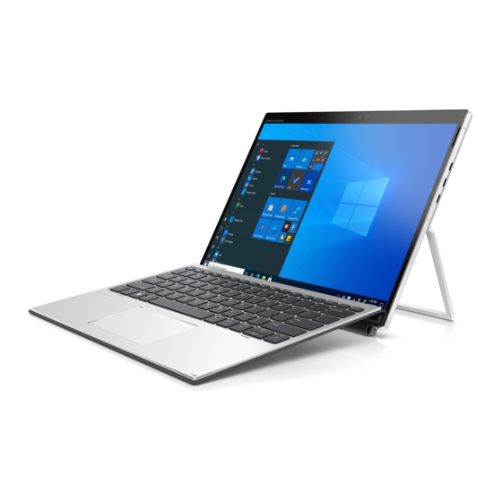
Page 11: Product Description
Product components and their descriptions Category Description Product Name HP Elite x2 G8 Tablet Processors Intel® Core™ processors, quad core Intel Core i7-1185 G7 (1.9 GHz, turbo up to 4.6 GHz, 16 MB SmartCache, 15 W) Intel Core i7-1185 G7 (1.8 GHz, turbo up to 4.6 GHz, 16 MB SmartCache, 15 W) Intel Core i7-1165 G7 (1.8 GHz, turbo up to 4.6 GHz, 16 MB SmartCache, 15 W) - Page 12 Category Description 128 GB, TLC, 2280, PCIe, 3 × 2 ● Audio and video Audio brand: HP Bang & Olufsen Audio Hybrid IR/RGB camera, front facing, 2 MP Rear-facing camera, 8 MP Two premium stereo speakers Wireless Wireless Local Area Network (WLAN) WLAN options via soldered minicard connector (PCIe/USB): Intel Wi-Fi 6 AX201 + Bluetooth®...
- Page 13 Duckhead (C5NS) Security TPM 2.0 SLB9670 (Infineon, soldered down) Pad fingerprint sensor (select products only) Preboot authentication (password, fingerprint) Hardware enforced Firmware Protection: HP Hardware Root of Trust Security lock Operating system Windows® 10 Home 64 Windows 10 Home 64 Advanced...
- Page 14 Table 1-1 Product components and their descriptions (continued) Category Description Win 10 Home 64 Plus Single Language Indonesia Market PPP Win 10 Home 64 Single Language Win 10 Home 64 Single Language Africa Market PPP Win 10 Home 64 Single Language APAC EM PPP Win 10 Home 64 Single Language India Market PPP Win 10 Home 64 Single Language Indonesia Market PPP Win 10 Pro 64...
-
Page 15: Components
The nano SIM card slot is located under the kickstand. USB Type-C® power connectors and Connect an AC adapter that has a USB Type-C connector, Thunderbolt™ ports with HP Sleep and Charge supplying power to the computer and, if needed, charging the computer battery. -
Page 16: Left
Table 2-1 Right-side components and their descriptions (continued) Component Description Connect a USB device, provide high-speed data transfer, and charge small devices (such as a smartphone), even when the computer is off. NOTE: Use a standard USB Type-C charging cable or cable adapter (purchased separately) when charging a small external device. -
Page 17: Display
For additional safety information, see the Regulatory, Safety, and Environmental Notices. To access this guide: Type HP Documentation in the taskbar search box, ▲ and then select HP Documentation. NOTE: When a device is connected to the jack, the computer speakers are disabled. - Page 18 For wireless regulatory notices, see the section of the Regulatory, Safety, and Environmental Notices that applies to your country or region. To access this guide: Type HP Documentation in the taskbar search box, and then select HP Documentation. ▲ Chapter 2 Components...
-
Page 19: Bottom
Bottom Use the illustration and table to identify the bottom components. Table 2-4 Bottom components and their descriptions Component Description Alignment connectors (2) Connect to the alignment connectors on the keyboard (select products only). Keyboard connector Connects the computer to the keyboard (select products only). -
Page 20: Rear
Table 2-5 Top components and their descriptions (continued) Component Description To conceal the camera, slide the cover to the right. ● Power button When the computer is off, press the button briefly to ● turn on the computer. When the computer is on, press the button briefly to ●... -
Page 21: Using The Kickstand
Table 2-6 Rear components and their descriptions Component Description Internal microphone Records sound. Camera Allows you to video chat, record video, and record still images. NOTE: Camera functions vary depending on the camera hardware and software installed on your product. Fingerprint reader (select products only) Allows a fingerprint logon to Windows, instead of a password logon. -
Page 22: Keyboard Area (Select Products Only)
Hold the computer with top edge up. Slide the kickstand away from the computer and position the kickstand at the appropriate angle. The kickstand will hold at a midway point (1) of approximately 52° or at full stopping point (2) of about 165°. To close the kickstand, push the kickstand against the bottom of the computer until it is flush with the bottom. -
Page 23: Removing The Keyboard
To connect the keyboard, lower the computer onto the keyboard until the connectors click into place. ▲ Removing the keyboard Use these steps to remove the keyboard from the computer. Removing the keyboard... -
Page 24: Touchpad
To remove the computer from the keyboard, pull the computer away from the back of the keyboard. ▲ Touchpad The touchpad settings and components are described here. Touchpad settings You learn how to adjust the touchpad settings and components here. Adjusting touchpad settings Use these steps to adjust touchpad settings and gestures. -
Page 25: Touchpad Components
Touchpad components Use the illustration and table to identify the touchpad components. Table 2-7 Touchpad components and their descriptions Component Description Touchpad zone Reads your finger gestures to move the pointer or activate items on the screen. Left touchpad button Functions like the left button on an external mouse. -
Page 26: Special Keys
Table 2-8 Lights and their descriptions Component Description Caps lock light On: Caps lock is on, which switches the key input to all capital letters. Fn lock light On: The key is locked. For more information, see Hot keys (select products only) on page Mute light On: Computer sound is off. -
Page 27: Action Keys
Table 2-9 Special keys and their descriptions Component Description Displays system information when pressed in combination with key. Executes frequently used system functions when pressed in combination with another key. Such key combinations are called hot keys. Hot keys (select products only) on page Windows key Opens the Start menu. - Page 28 Table 2-10 Action keys and their descriptions Icon Description Switches the screen image among display devices connected to the system. For example, if a monitor is connected to the computer, repeatedly pressing the key alternates the screen image from computer display to monitor display to simultaneous display on both the computer and the monitor.
-
Page 29: Hot Keys (Select Products Only)
Table 2-10 Action keys and their descriptions (continued) Icon Description Ability to change system profiles ● Ability to change system properties ● Executes user-defined key sequences ● NOTE: The action key feature is enabled at the factory. You can disable this feature by pressing and holding key and the left shift key. - Page 30 Table 2-12 Service label components Component Serial number Product ID HP product name Table 2-13 Service label components Component HP product name Product ID Serial number Warranty period Table 2-14 Service label components Component HP product name Warranty period Product ID...
-
Page 31: Using A Sim Card (Select Products Only)
Before purchasing a SIM card, follow these instructions to determine the correct SIM card size for your computer. Go to http://www.hp.com/support, and then search for your computer by product name or number. Select Product Information. Refer to the listed options to determine which card to purchase. - Page 32 Replace the tray in the computer. Press in gently on the tray (4) until it is firmly seated. To remove the SIM card, reverse these steps. Chapter 2 Components...
-
Page 33: Illustrated Parts Catalog
To identify the computer major components, use this illustration and table. NOTE: HP continually improves and changes product parts. For complete and current information about supported parts for your computer, go to http://partsurfer.hp.com, select your country or region, and then follow the on-screen instructions. NOTE: Details about your computer, including model, serial number, product key, and length of warranty, are on the service tag at the bottom of your computer. - Page 34 Table 3-1 Computer major component descriptions and part numbers Item Component Spare part number Display panel touch screen NOTE: Display spare parts are available as subcomponents, not as whole units. Display subcomponent spare parts are available. WUXGA+ M51632-001 WUXGA+, privacy M51634-001 3k ×...
- Page 35 Table 3-1 Computer major component descriptions and part numbers (continued) Item Component Spare part number Backlit M51231-001 Heat sink with fan L67416-001 (includes replacement thermal material) Solid-state drive 2 TB, PCIe, TLC L85358-005 1 TB, PCIe, TLC L85348-005 512 GB, PCIe, TLC + 32 GB Optane memory L85366-005 512 GB, PCIe, TLC, 2280 PCIe 3 ×...
-
Page 36: Plastics Kit
Table 3-1 Computer major component descriptions and part numbers (continued) Item Component Spare part number Battery, 2 cell, 47 Wh M33875-005 (10) WWAN module NOTE: The WWAN protective tape kit is available as spare part number M51648-001. Intel XMM 7360 LTE-Advanced (CAT 9) L70670-005 (11) Power button board and cable with audio assembly... -
Page 37: Miscellaneous Parts
M51660-001 Solid-state drive absorber M51635-001 IVO panel absorber M51661-001 WLAN cover kit M51647-001 WWAN cover kit M51648-001 HP Collaboration Keyboards For use in Belgium M51231-A41 For use in Brazil M51231-201 For use in Bulgaria M51231-261 For use in Canada M51231-DB1... - Page 38 Table 3-3 Miscellaneous part descriptions and part numbers (continued) Component Spare part number For use in Korea M51231-AD1 For use in Latin America M51231-161 For use in The Netherlands M51231-DH1 For use in Northwest Africa M51231-FP1 For use in Norway M51231-091 For use in Portugal M51231-131...
- Page 39 Table 3-3 Miscellaneous part descriptions and part numbers (continued) Component Spare part number North America L19367-001 People's Republic of China L19368-001 Saudi Arabia L19369-001 Switzerland L19370-001 Taiwan L19372-001 United Kingdom L19373-001 Power cords (C5, 1.0 m [3.3 ft]) (premium) Argentina L30811-001 Australia L22339-001...
- Page 40 Table 3-3 Miscellaneous part descriptions and part numbers (continued) Component Spare part number People's Republic of China L36823-001 Saudi Arabia L36824-001 Switzerland L36825-001 Taiwan L36827-001 United Kingdom L36828-001 Power cords (C5, 1.8 m [6.0 ft]) Argentina L19357-002 Australia L19358-002 Brazil L19359-002 Denmark L19360-002...
-
Page 41: Removal And Replacement Procedures Preliminary Requirements
Removal and replacement procedures preliminary requirements Use this information to properly prepare to disassemble and reassemble the computer. Tools required You need the following tools to complete the removal and replacement procedures: Tweezers ● Nonconductive, nonmarking pry tool ● Magnetic Phillips P1 screwdriver ●... -
Page 42: Electrostatic Discharge Information
Before handling a drive, be sure that you are discharged of static electricity. While handling a drive, avoid touching the connector. Before removing an optical drive, be sure that a disc is not in the drive, and be sure that the optical drive tray is closed. -
Page 43: Preventing Electrostatic Damage To Equipment
Table 4-1 Static electricity occurrence based on activity and humidity (continued) Relative humidity Motions of bench worker 400 V 800 V 6,000 V Removing DIPs (dual in-line packages) from plastic tube 400 V 700 V 2,000 V Removing DIPs from vinyl tray 2,000 V 4,000 V 11,500 V... -
Page 44: Grounding The Work Area
Use conductive field service tools, such as cutters, screwdrivers, and vacuums. ● Avoid contact with pins, leads, or circuitry. ● Recommended materials and equipment HP recommends certain materials and equipment to prevent static electricity. Antistatic tape ● Antistatic smocks, aprons, or sleeve protectors ●... -
Page 45: Cleaning Your Computer
Enabling HP Easy Clean (select products only) HP Easy Clean helps you to avoid accidental input while you clean the computer surfaces. This software disables devices such as the keyboard, touch screen, and touchpad for a preset amount of time so that you can clean all computer surfaces. -
Page 46: Cleaning Your Computer With A Disinfectant
Keep liquids away from the product. Avoid getting moisture in any openings. If liquid makes its way inside your HP product, it can cause damage to the product. Do not spray liquids directly on the product. Do not use aerosol sprays, solvents, abrasives, or cleaners containing hydrogen peroxide or bleach that might damage the finish. -
Page 47: Caring For Wood Veneer (Select Products Only)
When grounding is not possible, use an ionizer to dissipate electric charges. Accessing support information Use this information to find the HP support that you need. Caring for wood veneer (select products only) - Page 48 Search collect Chrome device logs. Technical bulletins To locate technical bulletins: Go to www.hp.com. Place the cursor over Problem solving to display more options. Select Support & Troubleshooting. Type the serial number, product number, or product name to go to the product support page.
- Page 49 Table 4-3 Support information locations (continued) Service consideration Path to access information Near the bottom of the window, select Notebook PCs, and the select your location. Accessing support information...
-
Page 50: Removal And Replacement Procedures For Customer Self-Repair Parts
NOTE: HP continually improves and changes product parts. For complete and current information about supported parts for your computer, go to http://partsurfer.hp.com, select your country or region, and then follow the on-screen instructions. You must remove, replace, or loosen as many as 44 screws when you service Customer Self-Repair parts. - Page 51 Remove the two Torx T5 2.0 × 3.5 screws from each side of the kickstand (1). Pull the sides of the kickstand away from the computer (2), and then remove the kickstand (3). To replace the kickstand, reverse the removal procedures. Kickstand...
-
Page 52: Removal And Replacement Procedures For Authorized Service Provider Parts
NOTE: HP continually improves and changes product parts. For complete and current information about supported parts for your computer, go to http://partsurfer.hp.com, select your country or region, and then follow the on-screen instructions. You must remove, replace, or loosen as many as xx screws when you service the parts described in this chapter. - Page 53 Table 6-1 Display panel and back cover descriptions and part numbers (continued) Description Spare part number Display panel, 3k × 2k M51633-001 IMPORTANT: Make special note of each screw size and location during removal and replacement. IMPORTANT: The display panel is fragile. Be sure to use no more force than necessary when removing the panel.
- Page 54 Position a suction tool at the top corner of the display panel (1), and then rotate the locking lever to lock the cup (2). To remove the panel evenly, secure the suction tool to each corner of the display panel, and then pull the suction tool handle (1) - (4) to release each section of the panel from the computer.
- Page 55 Rotate the top of the panel down enough to access the cables underneath (5). Lift the panel (1). Disconnect the battery cable (2) from the system board. IMPORTANT: Be careful when opening to avoid tearing cables. Be sure to open from the top Remove the tape from the display cable connector (3), and then disconnect the display cable (4) from the system board.
-
Page 56: Battery
Remove the tape from the touch cable connector (5), and then disconnect the touch cable from the system board (6). Reverse this procedure to reassemble and replace the display panel. Battery To remove the battery, use this procedure and illustration. Table 6-2 Battery description and part number Description... - Page 57 WARNING! To reduce potential safety issues, use only the user-replaceable battery provided with the computer, a replacement battery provided by HP, or a compatible battery purchased from HP. IMPORTANT: Removing a battery that is the sole power source for the computer can cause loss of information.
-
Page 58: Solid-State Drive
Carefully rotate the top of the battery up (1), and the lift the battery out of the computer (2). To insert the battery, reverse the removal procedures. Solid-state drive To remove the M.2 solid-state drive, use this procedure and illustration. Table 6-3 Solid-state drive descriptions and part numbers Description... -
Page 59: Sim Card Holder Board
Remove the solid-state drive: Remove the tape from the solid-state drive (1). Remove the Phillips M1.4 × 1.6 screw (2), and then remove the solid-state drive (3). To install the solid-state drive, reverse the removal procedures. NOTE: Solid-state drives are designed with a notch to prevent incorrect insertion. SIM card holder board To remove and disassemble the SIM card holder board, use these procedures and illustrations. -
Page 60: Kickstand Hinges
Insert a tool into the opening in the SIM card tray (1), and then remove the SIM card and tray (2). Disconnect the cable from the ZIF connector on the system board (1). Peel the cable off the computer chassis (2). Remove the two Phillips M1.4 ×... -
Page 61: Wwan Module
Before removing the kickstand, follow these steps: Prepare the computer for disassembly (see Preparation for disassembly on page 40). Remove the kickstand (see Kickstand on page 40). Remove the display panel (see Display panel on page 42). Remove the kickstand: From the bottom, rotate the hinges up (1). - Page 62 Before removing the WWAN module, follow these steps: Prepare the computer for disassembly (see Preparation for disassembly on page 40). Remove the display panel (see Display panel on page 42). Disconnect the battery cable from the system board (see Battery on page 46).
-
Page 63: Pogo Connector
Reverse this procedure to install the WWAN module. POGO connector To remove and disassemble the POGO connector, use these procedures and illustrations. Table 6-7 POGO connector descriptions and part numbers Description Spare part number POGO connector and cable L67422-001 IMPORTANT: Be sure to use the correct size screwdriver to avoid stripping the screw. - Page 64 Table 6-8 Camera module descriptions and part numbers Description Spare part number IR camera (2 MP) L67412-001 HD camera (8 MP) M75415-001 Microphone cable L67421-001 IR LED cable M75416-001 IMPORTANT: Use care to prevent damaging the zero-insertion force (ZIF) connector and ribbon cable. Before removing the display panel, follow these steps: Prepare the computer for disassembly (see Preparation for disassembly on page...
-
Page 65: Speakers With Antennas
Speakers with WWAN antennas M51639-001 Speakers with GPS antennas L67429-001 Speakers with WWAN antennas for HP INT XMM 7360 LTE w/GPS M.2 L70670-005 Before removing the speakers, follow these steps: Prepare the computer for disassembly (see Preparation for disassembly on page 40). - Page 66 Disconnect the battery cable from the system board (see Battery on page 46). Remove the speakers and antennas: Disconnect the WLAN antenna cables from WLAN module (1). Disconnect the WWAN antenna cables from the WWAN module (2). Disconnect the speaker cables from the system board (3). Disconnect the camera cables from the system board (4) to remove the speaker antennas that run underneath them.
- Page 67 Use the following illustrations to help with installing the antennas and speakers by noting the location of (1) computer notches and (2) speaker snaps. To install the number 1 antenna cable, insert the cable into the slots (1) and (2), and then place the contact over the cable (3).
- Page 68 To install the number 6 and 8 antenna cables, insert the cables into the slots (1) and (2), and then place the contact over the cables (3). When installing the right speaker, lift the right side of the speaker (1), and insert the notch on the speaker into the snap in the computer (2).
-
Page 69: Antenna Removal
To install the left speaker, insert the speaker into the computer (1), place the notch on the speaker (2) into the snap in the computer (3), and then make sure the left channel of the speaker fits under the left notch in the computer (4). -
Page 70: Power Button Board
Reverse this procedure to reassemble and replace the POGO connector. Power button board To remove the power button board, use this procedure and illustration. Table 6-10 Power button board description and part number Description Spare part number Power button board L67420-001 Before removing the power connector cable, follow these steps: Prepare the computer for disassembly (see... -
Page 71: Volume Board
Lift the assembly out of the computer (4). NOTE: The plastic power button can be removed, once the board is removed. Reverse this procedure to install the power button board. Volume board To remove the volume board, use this procedure and illustration. Table 6-11 Volume board description and part number Description... -
Page 72: Fingerprint Reader Board
Be careful not to tear the cable as you gently pull up the connector, and then remove the assembly from the computer (4). Reverse this procedure to install the volume board. Fingerprint reader board To remove the fingerprint reader board, use this procedure and illustration. Table 6-12 Fingerprint reader board description and part number Description... -
Page 73: System Board
Rotate the bracket upward (2), disconnect the cable from the ZIF connector on the fingerprint reader, and then remove the board from the computer (3). Reverse this procedure to install the fingerprint reader board. System board To remove the system board, use these procedures and illustrations. Table 6-13 System board descriptions and part numbers Description... - Page 74 Prepare the computer for disassembly (see Preparation for disassembly on page 40). Remove the display panel (see Display panel on page 42). Remove the battery (see Battery on page 46). Remove the solid-state drive (see Solid-state drive on page 48). Remove the system board: Disconnect the following cables from the system board: SIM card holder board cable (1)
- Page 75 Remove the SIM card insert (1). Peel the WLAN antennas off the heat sink (2) Remove the two Phillips M1.4 × 2.5 screws (3) that secure the USB Type-C bracket to the computer. Remove the USB Type-C bracket (4). Remove the four Phillips M1.4 × 1.6 screws (2) that secure the system board to the computer (5), and then remove the system board from the computer (6).
-
Page 76: Heat Sink With Fan
Heat sink with fan To remove the heat sink, use these procedures and illustrations. Table 6-14 Heat sink descriptions and part numbers Description Spare part number Heat sink with fan L67416-001 Before removing the heat sink, follow these steps: Prepare the computer for disassembly (see Preparation for disassembly on page 40). - Page 77 Remove the heat sink from the computer (4). Thoroughly clean the thermal material from the surfaces of the heat sink and the system board components each time the heat sink is removed. Replacement thermal material is included with the heat sink and system board spare part kits. The following illustration shows the replacement thermal material locations.
-
Page 78: Troubleshooting Guide
Based on some of the most common symptoms, this chapter identifies logical steps and available resources or tools for resolving an issue. HP recommends that you follow the instructions carefully, observe safety precautions, and note any observations or results. Capturing this information can help identify and resolve the problem more quickly. -
Page 79: General Troubleshooting Steps
Proceed through the steps in the following table until the issue is resolved, and then move on to the next step that is relevant to the issue. For example, if you resolve a memory issue using the HP PC Diagnostics (UEFI) tool in step 6, you can then move on to step 10 to reseat the memory into its memory slot. -
Page 80: Boot Up Sequence
Power-On Self-Test (POST) verifies that hardware components (such as processor, hard drive, memory) are functional. When POST is complete, the HP logo appears briefly and then disappears. If there are errors, the computer may exhibit blinking lights and POST error messages, and so on. - Page 81 Battery discharges too fast on page No wake up on page 99 Unresponsive on page 100 Burnt smell on page 91 Slow performance on page 101 HP Smart Adapter warning message on page 101 Incorrect time and date on page 102 a,b,c similar symptoms Failure classification by hardware devices To determine failure by device, use this table.
-
Page 82: Examine The Environment
Table 7-5 Failure classification by hardware devices (continued) 4. Display 5. I/O devices 6. Storage 7. Mechanical No video (external) on Touchpad on page 111 Read-write error on page page 105 Network connectivity (RJ-45 jack) on page 112 Slow performance on DisplayPort/VGA on page page 120 Network connectivity... -
Page 83: Manually Updating Bios And Drivers
6. HP Hardware Diagnostics and Tools HP offers diagnostics and tools to diagnose hardware failure. This section describes how to use some of these tools. Make sure to check for the latest versions before use. HP PC Hardware Diagnostics (UEFI) HP PC Hardware Diagnostics is a Unified Extensible Firmware Interface (UEFI) that allows you to run diagnostic tests to determine whether the computer hardware is functioning properly. - Page 84 In addition, for HP authorized service partners and IT professionals who need to support a mixed environment of older and newer HP/Compaq PCs, the HP PC Hardware Diagnostics Tool http://www8.hp.com/us/en/campaigns/hpsupportassistant/pc-diags.html?jumpid=va_r602_us/en/any/pps/pl_ot_ob_ds_p ) supports a wide range of HP computers. The tool runs outside the operating system so that it can isolate hardware failures from software issues, whether caused by the operating system or applications.
-
Page 85: Hp Bios Configuration Utility (Bcu)
HP BIOS Configuration Utility (BCU) HP BCU is a free utility that captures the BIOS settings and their values. This tool provides a text file of the computer’s BIOS configuration. This file can help identify any settings that may be contributing to an issue. -
Page 86: Non Hp Diagnostics Tools
Non HP diagnostics tools Refer to the following diagnostic tools for troubleshooting help. Windows-to-Go USB Windows-To-Go USB is a Microsoft-based tool for Enterprise editions of Windows that can help in troubleshooting. You can find a process online about how to create a live Windows USB drive. For more information, see https://technet.microsoft.com/en-us/library/hh831833.aspx. -
Page 87: Blinking Light Codes
POST checks the following items to ensure that the computer system is functioning properly: Memory ● Processors ● BIOS ● Mass storage devices ● Fans ● The following table describes errors encountered during HP PC Hardware Diagnostics (UEFI). Blinking light codes... -
Page 88: Resolve The Issue
Primary Battery Replace This message indicates that the primary battery has very low capacity. Search for support documentation at http://www.hp.com/support for details on using the HP Support Assistant to verify the battery capacity and, if necessary, order a replacement. Wireless Modules Not installed or responding Reseat the wireless LAN adapter module and antennas. -
Page 89: Soft Reset (Default Settings)
Before performing a hard reset, you must disconnect or remove all peripheral devices. Start and test the computer by itself, and if the problem is not resolved, reconnect one peripheral device at a time. To resolve the startup or operational problem, run HP Support Assistant, or manually install all updated drivers from Microsoft and HP. -
Page 90: 10. Reseat Cables And Connections
In addition to removing recently added components, you can narrow the issue down further with a ● minimum configuration. For example, if HP PC Diagnostics reports a memory error, test one memory module at a time to isolate the defective module. -
Page 91: Essential Hardware Configuration
NOTE: This step is to be used by authorized service providers only. HP will not honor the warranty for a system tested with the system board removed without the heat sink or fan. -
Page 92: Test With Verified Working Configuration (Hardware Or Operating System)
● Cables or connections are loose. ● Technician is unaware of information available from the HP Support website (CA - Customer Advisory). ● The issue is related to existing or known issues that might be identified in existing support articles. -
Page 93: Verify Solution
HP public document, provide the document information to the customer, letting them know they can locate it on http://www.hp.com. Also, tell them that there are other solutions available on the website. Advise the customer to check the website first when they have an issue. It might save them time calling in. -
Page 94: Consulting With Hp Service
Press the touchpad On/Off button light. If the light toggles on or off, the touchpad is likely operating correctly. Consulting with HP Service If further HP support is required, this information may be requested when you call. So it may be helpful to take notes. Technical support registration number (if applicable) ●... -
Page 95: Common Issues And Possible Solutions
Third-party hardware or software ● Operating system type and revision level ● Description of symptom or failure ● Common issues and possible solutions This section contains common issues, symptoms, and a series of tables that describe possible solutions to issues from Failure Classification tables. The following sections identify the issue with symptoms and solutions to resolve an issue. - Page 96 Replace new power connector cable (if the cable exists and is defective) To isolate faulty power connector cable and power button, technicians can short power-on pads or pins to turn on the computer. Contact HP Engineering for this information. Verify blinking lights (7.
-
Page 97: Intermittent Power-On, Shutdown, Reboot
Table 7-9 Issues, possible causes, and fixes (continued) Items Procedures Tips Computer automatically boots without pressing power button when the RTC 3 V battery is removed. Therefore, after the service door and RTC 3 V battery are removed, you do not have to press power button from top side. In essential hardware configuration, mWS G1 and G2 may require discrete graphics processing unit (GPU) to boot. -
Page 98: Ac Adapter Issue
If there is still no rear power light or no boot, replace the AC adapter. Tips The HP Smart AC adapter has a special pin in the middle, called the ID pin, for power rating and throttling. If this pin is broken, the rear power light turns on, but the power button and front power lights blink continuously, and the computer does not turn on. - Page 99 Use HP Hardware Diagnostics (UEFI) (6. HP Hardware Diagnostics and Tools on page HP PC Hardware Diagnostics (UEFI) is a good tool to use to isolate and determine faulty battery, especially for quickly discharging (short life) battery. Verify that battery is recognized and charging.
-
Page 100: Battery Discharges Too Fast
Test and calibrate battery using HP PC Hardware Diagnostics (UEFI). Verify battery life cycle using HP Support Assistant tool. If battery cycle life is past its life expectancy (past the 1000-cycle life and 3-year warranty), the battery might need to be replaced. -
Page 101: Burnt Smell
Inspect further sources internally after disassembling chassis, such as burnt or damaged components. If the issue persists, replace boards, AC adapter, and battery for safety concern, and report issues to HP. POST Use the following sections to troubleshoot Power-on Self Test issues. -
Page 102: Blinking Lights
Perform hardware reset (8. Hard reset on page 78) and verify that HP Logo is presented correctly on display screen when pressing f10. Test with external monitor via VGA port (or DisplayPort, HDMI, or other). Press power button and close the computer lid to force video output to external video. -
Page 103: Diagnostic Error Messages
Restore hardware to its original condition (for example, bootable solid-state drive instead of hard drive). Reseat suspected components and verify connection. Test suspected components using HP PC Hardware Diagnostics (UEFI) tool. Note An Error Message means that the system has finished BIOS hardware validation and is ready to launch the Startup Menu. -
Page 104: Performance (Os)
HP F10 Setup Overview http://h10032.www1.hp.com/ctg/Manual/c04460979 http://h10032.www1.hp.com/ctg/Manual/c04685655 2015 Business PC models: see the HP PC BIOS F10 Setup Guide at http://support.hp.com. Performance (OS) Most software problems occur as a result of certain situations. The application was not installed or configured correctly. - Page 105 Verify functionality of AC adapter alone. If it does not work, test with a verified working adapter. Verify battery alone. Verify that battery is not depleted. Test battery using HP PC Hardware Diagnostics (UEFI) tool. Verify connection of power button and cable.
-
Page 106: Blue Screen
(6. HP Hardware Diagnostics and Tools on page 73) to isolate major faulty hardware issues. HP PC Hardware Diagnostics (UEFI) tool to test hard drive, memory, and system. ● Thermal Monitor (available only to authorized service providers and technicians) tool to monitor ●... -
Page 107: Freeze At Windows Logo (Hang Or Lockup)
Conflict of instructions from multiple programs or drivers; installing a new hardware ● or program that is not compatible (may also cause a blue screen error—see blue HP Logo displays briefly ● screen issue). Attempt to boot to operating system and ●... -
Page 108: Electromagnetic Interference (Emi)
Roll back to previous version may be necessary. Go to safe mode to install drivers. Run Hardware Diagnostics (6. HP Hardware Diagnostics and Tools on page to isolate hardware issue. Undo recent changes in Windows (5. Remove or uninstall recently added hardware, software on page 73). -
Page 109: No Wake Up
Table 7-22 Issues, possible causes, and fixes (continued) Items Procedures (2. Examine the environment on page 72). Pay attention to external power source, high-frequency signals such as cell phones, microwave ovens. Move the computer to different locations nearby to determine where it fails and where it does not fail. -
Page 110: Unresponsive
Table 7-23 Issues, possible causes, and fixes (continued) Items Procedures Screen saver is set. Press any key or touch touchpad to resume. Verify that Display Choice is set to external video only. Toggle screen control key combination fn + f4 Windows logo Tips If you are using a docking station, set your notebook display as a primary display. -
Page 111: Slow Performance
Tips Routine maintenance for performance improvement on page 129). See http://windows.microsoft.com/en-us/windows-8/free-up-disk-space. http://windows.microsoft.com/en-us/windows/optimize-windows-better performance#optimize-windows-better-performance=windows-vista. HP Smart Adapter warning message Use this information to troubleshoot power adapter warning messages. Table 7-26 Issues, possible causes, and fixes Items Procedures Symptom... -
Page 112: Incorrect Time And Date
Display anomalies The display panel is a field-replaceable unit (FRU) and must be replaced by only authorized technicians. However, HP highly recommends that users and technicians observe symptoms and use the HP PC Hardware Diagnostics (UEFI) tool before any replacement. -
Page 113: Symptom
Symptom This section includes common display issues with symptoms: Blank or black video ● Incorrect color, missing color, distorted image ● Flickering image ● Vertical lines (because of LDVS, decreased signal integrity, and data loss) ● Dead pixel (because of display liquid, internal transistor, and others) ●... -
Page 114: Hp Pc Hardware Diagnostics (Uefi) For Video Test
● Palette Check: to test the three video color components (red, green, blue) ● Dead Pixel Check: to check dead pixels in eight different colors (Dead Pixel Check is available with the HP ● PC Diagnostics 3-in-1 USB Key tool) Review the video troubleshooting in the following Display section for specific issues and possible solutions. -
Page 115: Dead Pixel
Use an external monitor with higher resolution. Test with external monitor using HDMI or HP port. Press the power button and close the computer lid to force video output to external video. If there is still no video, contact support. -
Page 116: Displayport/Vga
Table 7-30 Issues, possible causes, and fixes Items Procedures Symptom Possible causes No image on external External monitor, resolution, display configuration, drivers. monitor Troubleshooting steps Be sure external monitor is compatible with the computer. Be sure that external monitor is turned on. Press any key to exit the power-saving mode. -
Page 117: No Or Bad External Video Via Docking
Be sure that external monitor is compatible with the computer. If applicable, plug the dock in different Type-C ports. For more information, see the technical white paper titled ”HP Elite Dock with Thunderbolt 3 & HP ZBook Dock with Thunderbolt 3.” Go to http://www.hp.com/... -
Page 118: Touch Screen
Configure the touch display to identify the screen as a touch screen as shown in the image at left. Calibrate the screen and reset if touch functionality is still not working correctly. Perform diagnostic test in HP Hardware Diagnostics under Component Tests > Touch Screen. Chapter 7 Troubleshooting guide... -
Page 119: I/O Devices
Be sure that external devices are supported and compliant (for example, USB Type-C®, Thunderbolt 3, ● PCI Express). If you have problems with external devices not provided by HP, contact device manufacturers for ● compatibility and latest drivers before troubleshooting (for example, USB devices, Thunderbolt devices, PCI express card reader, VGA, display, HDMI monitors, speakers). -
Page 120: Keyboard Pointing Stick (Select Products Only)
(caps lock, shift, ctrl, fn, Windows, alt) if necessary. Test with HP PC Hardware Diagnostics (UEFI) to isolate a hardware issue from a software issue. Verify that BIOS is up to date. If so, resetting BIOS to default may help. -
Page 121: Keyboard Backlight
Table 7-36 Issues, possible causes, and fixes (continued) Items Procedures Verify whether keyboard flex cables are in good condition (no delamination or torn cable end, no missing or cracked tracks, pads). Verify that keyboard flex cable ends are fully inserted and aligned with connectors on system board and back of keyboard, and that connector tabs are properly closed. -
Page 122: Network Connectivity (Rj-45 Jack)
Install the latest touchpad driver. Adjust touchpad settings (Control Panel > Mouse). Test touchpad controller using the HP PC Hardware Diagnostics (UEFI) tool (f2> Component Tests > Mouse Test > Pointer Test & Drag and Drop Test). The following steps are for authorized service providers/technicians. -
Page 123: Wwan
Table 7-40 Issues, possible causes, and fixes (continued) Items Procedures Verify that the wireless module and its antenna cables are fully inserted and in good condition (see WLAN module removal and replacement section). Reseat wireless module and antenna connection. Verify the module antenna cable connection is not loose. Verify that antenna cables are properly connected to the MAIN and AUX terminals (see WLAN module removal and replacement section). -
Page 124: Smart Card Reader
Table 7-42 Issues, possible causes, and fixes (continued) Items Procedures Examples of USB device Not Recognized Troubleshooting steps Unplug the USB device. Restart the computer (wait for 2–5 minutes) to reset the USB port or hub in case of a power surge. Perform a soft reset (9. -
Page 125: Speaker, Headphone - Audio Issues
Be sure that the sound is not muted. Verify that the sound card is detected in Windows Device Manager. Reinstall the latest audio driver. Test audio device using HP PC Hardware Diagnostics (UEFI) tool > Component Tests > Audio). Test with a verified working operating system. If issue is resolved, restore full operating system. -
Page 126: Thunderbolt (Tb)
Table 7-44 Issues, possible causes, and fixes (continued) Items Procedures Reseat internal speaker connections. 10. Test with verified working internal speakers. 11. Replace internal speakers. No sound from headphones Adjust volume by pressing fn + f6 or f7. Be sure that volume button light is not amber (mute). -
Page 127: Storage
NOTE: Back up all critical data before troubleshooting the drive. ● Before contacting support, HP recommends that you run a drive (HDD, SSD, M.2 drive) test using the HP ● PC Hardware Diagnostics (UEFI) tool on the suspected failed drive. -
Page 128: Hard Drive Or Solid-State Drive Not Recognized
If all of the tests pass, the hard drive is not damaged. As a rule, HP will not replace a hard drive under ● warranty that does not fail the HP Hard Drive Self-Test. If there is no physical problem with the hard drive (or memory), then try reinstalling the Windows ●... -
Page 129: No Boot To Operating System (No Read-Write Error)
(10. Reseat cables and connections on page 80). Use the HP Hardware Diagnostics tool to test. If failed, record failure code and have the hard drive replaced. If no error with HP PC Hardware Diagnostics (UEFI) tool, try to repair the hard drive and its files in Windows (using command “CHKDSK /f /r /x”). -
Page 130: Slow Performance
129). Blue screen (BSOD) error A faulty hard drive can cause a blue screen error. Perform the drive tests using the HP Diagnostics Tool to be sure that the drive is functional. If all of the tests are successful, see... -
Page 131: Mechanical
Verify original hard drive connection and flex cable. Reseat hard drive and connection. Run HP PC Hardware Diagnostics (UEFI). If failed, record failure code and replace hard drive replace. If you find no error with HP PC Hardware Diagnostics (UEFI), perform disk defragmentation. -
Page 132: Fan Runs Constantly
Table 7-51 Issues, possible causes, and fixes (continued) Items Procedures Noisy hard drive Determine whether the noise comes from the hard drive. Noisy hard drive on page 120. Noisy optical drive Determine whether the noise comes from an optical drive. Remove CD/DVD from the optical drive. -
Page 133: Thermal Shutdown (Hot)
Fan often is part of thermal solution, including heat sink, heat sink fin/muffler, and thermal grease. Fan replacement requires reboot and fan function verification using HP PC Hardware Diagnostics (UEFI) tool. For more information, see the following links: http://support.hp.com/us-en/document/c01007591. -
Page 134: Additional Information
Be sure that no obstructions or dust are in heat sink fan, fin, or vent. Be sure that the notebook is not sitting on a hot surface that blocks vent intakes. Test fan using HP PC Hardware Diagnostics (UEFI) tool (6. HP Hardware Diagnostics and Tools on page 73). -
Page 135: Blinking Lights And Boot Error Codes
In some cases, when the host processor is not executing code or does not have the necessary code to drive the display, light blink codes inform you of a problem. The following information is from the white paper http://h10032.www1.hp.com/ctg/Manual/c04685655. Table 7-54... -
Page 136: Bios Recovery Code Unable To Find Valid Bios Recovery Image
BIOS recovery code unable to find valid BIOS recovery image This computer has experienced a problem in locating a valid BIOS image, resulting in a failed startup. You can resolve this problem by placing a clean copy of the system BIOS on a USB key or in the appropriate hard drive directory and performing a reboot. -
Page 137: Sure Start Unable To Find Valid Bios Boot Block Image
Sure Start has identified a problem (Manual Recovery Policy Set) This computer has experienced a problem in locating a valid BIOS image, resulting in a failed startup. HP Sure Start normally repairs this type of issue; however, on this computer HP Sure Start has been configured to operate in manual mode key sequence. - Page 138 The hard drive might have failed. Contact support for assistance. Run-in test Memory module Attempt to reseat the memory module and then repeat the test. Search http://www.hp.com/support for details about troubleshooting issues related to the memory module. If the memory module still fails, contact support. Run-in test Hard Disk 1 SMART Attempt to reseat the hard drive and repeat the test.
-
Page 139: Routine Maintenance For Performance Improvement
Primary Battery This code indicates that the primary battery has very low capacity. Replace Search http://www.hp.com/support for details about using the HP Support Assistant to verify the battery capacity and, if necessary, order a replacement. Battery Check Secondary Battery This indicates that the secondary battery has very low capacity. -
Page 140: Common Blue Screen Error Messages
If you recently added hardware to the system, try removing or replacing it. Or check with the ● manufacturer to see if any patches are available. Try running HP PC Hardware Diagnostics (UEFI). ● Check with the manufacturer to see if an updated system BIOS or firmware is available. -
Page 141: Use Windows Debugging Tool
If new device drivers or system services have been added recently, try removing or updating them. ● NOTE: Use safe mode when removing or disabling components. Safe mode loads only the minimum required drivers and system services during the Windows startup. To enter safe mode, restart your computer and press at the menu that displays the operating system choices. - Page 142 Set up the SDK in the configuration window (Windows 10 shown). Select features to install. Chapter 7 Troubleshooting guide...
- Page 143 Run the SDK as an administrator. Set the symbol path. Select File > Symbol File Path. In the Symbol path box, type ● SRV*C:\Windows\symbol_cache*http://msdl.microsoft.com/download/symbo Save the workspace. ● Windows Software Development Kit (SDK)
- Page 144 Open the crash dump file. Analyze the file. In the following memory dump sample, look for Bug Check 0x3B. The ATIKMAG driver needs to be investigated for further root cause. Lookup for Bug Check 0xC2. Chapter 7 Troubleshooting guide...
-
Page 145: Display Issue: Pixel Anomalies
Display issue: pixel anomalies All HP notebook displays adhere to strict quality and reliability specifications. A small percentage of display panels might have minor cosmetic manufacturing anomalies or irregularities such as bright or dark dots in the viewable area. These cosmetic imperfections are common to all display panel types, not specifically HP products. -
Page 146: Cable Management
Combination = in any combination and any color that are always on or off ● Use the HP PC Hardware Diagnostics (UEFI) tool to determine numbers of pixels and their distance. HP uses the following set of criteria when damaged displays are submitted for warranty coverage. -
Page 147: Connector Types
Route cables in such a way that they cannot be caught or snagged by parts being removed or replaced. ● Keep cables away from direct contact with major heat sources, such as the heat sink. (Some air flow ● guides have a cable guide that lets you route cables safely around the heat sink.) Do not jam cables on top of daughterboards or memory modules (DIMMs). -
Page 148: Horizontal Cable Insertion
Horizontal cable insertion Use flat tool to pull connector evenly. Do not pull on cable to remove. Slide connector into receptacle on same horizontal plane as board and use a flat tool to push evenly into receptacle. Multiple-pin horizontal connector (LVDS cable to display panel) Use these procedures to properly insert and remove a multiple-pin horizontal connector. - Page 149 If the connector has a plastic pull tab, pull the tab to disconnect. Otherwise, use flat tool under the ● connector to remove evenly. Do not pull on the cable to remove. Press evenly when reseating, reconnecting, or installing the connector. ●...
-
Page 150: Using Setup Utility (Bios)
Start menu is displayed. Updating Setup Utility (BIOS) Updated versions of Setup Utility (BIOS) might be available on the HP website. Most BIOS updates on the HP website are packaged in compressed files called SoftPaqs. Some download packages contain a file named Readme.txt, which contains information regarding installing and troubleshooting the file. -
Page 151: Preparing For A Bios Update
Downloading a BIOS update After you review the prerequisites, you can check for and download BIOS updates. Type support in the taskbar search box, and then select the HP Support Assistant app. – or – Select the question mark icon in the taskbar. - Page 152 Using the hard drive path you recorded earlier, open the folder that contains the update. Double-click the file that has an .exe extension (for example, filename.exe). The BIOS installation begins. Complete the installation by following the on-screen instructions. NOTE: After a message on the screen reports a successful installation, you can delete the downloaded file from your hard drive.
-
Page 153: Computer Setup (Bios), Tpm, And Hp Sure Start
NOTE: Use extreme care when making changes in Computer Setup. Errors can prevent the computer from operating properly. To start Computer Setup, turn on or restart the computer, and when the HP logo appears, press to enter Computer Setup. Navigating and selecting in Computer Setup You can navigate and select in Computer Setup using one or more methods. -
Page 154: Updating The Bios
Updating the BIOS Updated versions of the BIOS might be available on the HP website. Most BIOS updates on the HP website are packaged in compressed files called SoftPaqs. Some download packages contain a file named Readme.txt, which contains information regarding installing and troubleshooting the file. -
Page 155: Downloading A Bios Update
Downloading a BIOS update After you review the prerequisites, you can check for and download BIOS updates. Type support in the taskbar search box, and then select the HP Support Assistant app. – or – Select the question mark icon in the taskbar. -
Page 156: Tpm Bios Settings (Select Products Only)
If the BIOS becomes corrupted or is attacked, HP Sure Start automatically restores the BIOS to its previously safe state, without user intervention. HP Sure Start is configured and already enabled so that most users can use the HP Sure Start default configuration. Advanced users can customize the default configuration. -
Page 157: Backing Up, Resetting, And Recovering
Backing up, resetting, and recovering This chapter provides information about processes that are standard procedure for most products. Backing up You can back up your data to an optional USB flash drive or SD memory card or through Google Drive. For detailed information about creating a backup, go to http://www.support.google.com. -
Page 158: Installing The Chromebook Recovery Utility
saved files and saved networks are deleted for all accounts. Your Google Accounts and any data synced to your Google Drive™ storage are not affected by a system recovery. NOTE: For more information about performing a system recovery on your computer, go to http://www.support.google.com Before beginning the recovery process, you need the following: A USB flash drive or SD memory card with a capacity of 4 GB or greater. -
Page 159: Setting Up Your Computer After A Reset Or Recovery
To enter recovery mode, press and hold + f3, and then press the power button. When the “Chrome OS is missing or damaged” screen displays, insert the recovery media into your computer. The recovery process begins immediately. Wait while Chrome verifies the integrity of the recovery media. NOTE: If you need to cancel the recovery during the verification process, press and hold the power button until the computer turns off. -
Page 160: Backing Up, Restoring, And Recovering
Using the HP Cloud Recovery Download Tool to create recovery media (select products only) You can use the HP Cloud Recovery Download Tool to create HP Recovery media on a bootable USB flash drive. For details: Go to http://www.hp.com/support, search for HP Cloud Recovery, and then select the result that ▲... -
Page 161: Creating A System Restore
You can use HP Recovery media to recover the original operating system and software programs that were installed at the factory. On select products, it can be created on a bootable USB flash drive using the HP Cloud Recovery Download Tool. -
Page 162: Changing The Computer Boot Order
Changing the computer boot order If your computer does not restart using the HP Recovery media, you can change the computer boot order, the order of devices listed in BIOS for startup information. You can select an optical drive or a USB flash drive, depending on the location of your HP Recovery media. -
Page 163: Using Hp Pc Hardware Diagnostics
● Accessing HP PC Hardware Diagnostics Windows After HP PC Hardware Diagnostics Windows is installed, you can access it from HP Help and Support, HP Support Assistant, or the Start menu. Accessing HP PC Hardware Diagnostics Windows from HP Help and Support (select products only) After HP PC Hardware Diagnostics Windows is installed, follow these steps to access it from HP Help and Support. -
Page 164: Accessing Hp Pc Hardware Diagnostics Windows From Support Assistant
To stop a diagnostic test, select Cancel. Accessing HP PC Hardware Diagnostics Windows from the Start menu (select products only) After HP PC Hardware Diagnostics Windows is installed, follow these steps to access it from the Start menu. Select the Start button. -
Page 165: Downloading Hp Hardware Diagnostics Windows By Product Name Or Number (Select Products Only)
Downloading HP PC Hardware Diagnostics UEFI to a USB flash drive on page 156. If your PC does not start in Windows, you can use HP PC Hardware Diagnostics UEFI to diagnose hardware issues. Using an HP PC Hardware Diagnostics UEFI hardware failure ID code When HP PC Hardware Diagnostics UEFI detects a failure that requires hardware replacement, a 24-digit failure ID code is generated. -
Page 166: Starting Hp Pc Hardware Diagnostics Uefi
.exe files are provided. Downloading the latest HP PC Hardware Diagnostics UEFI version To download the latest HP PC Hardware Diagnostics UEFI version to a USB flash drive, follow this procedure. Go to http://www.hp.com/go/techcenter/pcdiags. The HP PC Diagnostics home page is displayed. -
Page 167: Using Remote Hp Pc Hardware Diagnostics Uefi Settings (Select Products Only)
Find out more. Downloading Remote HP PC Hardware Diagnostics UEFI HP Remote PC Hardware Diagnostics UEFI is also available as a SoftPaq that you can download to a server. Downloading the latest Remote HP PC Hardware Diagnostics UEFI version You can download the latest HP PC Hardware Diagnostics UEFI version to a USB flash drive. - Page 168 Display status information about the diagnostics run previously. ● To customize Remote HP PC Hardware Diagnostics UEFI settings, follow these steps: Turn on or restart the computer, and when the HP logo appears, press to enter Computer Setup. Select Advanced, and then select Settings.
-
Page 169: Specifications
Specifications This chapter provides specifications for your computer. Computer specifications This section provides specifications for your computer. When you travel with your computer, the computer dimensions and weights, as well as input power ratings and operating specifications, provide helpful information. Table 13-1 Computer specifications Tablet... - Page 170 Table 13-2 Display specifications Metric U.S. Active diagonal size 33.02 cm 13.0 in Surface treatment 3k × 2k (BrightView) WUXGA+ (antiglare) Brightness 400 nits (nonprivacy WUXGA+) 450 nits (3k × 2k) 1000 nits (privacy panel WUXGA+) Pixel resolution 3000 × 2000 (3k × 2k) 1920 x 1280 (WUXGA+) Viewing angle UWVA...
-
Page 171: Statement Of Memory Volatility
No applications, features, or functionality were added to or installed on the system. ● Following system shutdown and removal of all power sources from an HP business computer system, personal data can remain on volatile system memory (DIMMs) for a finite period of time and also remains in nonvolatile memory. - Page 172 If an asset or ownership tag is set, select the Security menu and scroll down to the Utilities menu. Select System IDs, and then select Asset Tracking Number. Clear the tag, and then make the selection to return to the prior menu. If a DriveLock password is set, select the Security menu, and scroll down to Hard Drive Utilities under the Utilities menu.
-
Page 173: Nonvolatile Memory Usage
8 MB Provides Data cannot be written to This memory is flash (select protected this device via the host protected by the HP models only) backup of processor. The content is Sure Start Embedded critical managed solely by the Controller. - Page 174 A utility must be Computer Setup (BIOS) or used for writing a custom utility. data to this memory and is available on the HP website; go http://www.hp.com/ support. Select Find your product, and then follow the on-screen instructions. Intel 1.5 MB or 7...
-
Page 175: Questions And Answers
HP ProtectTools Security flash. Manager. Questions and answers Use this section to answer your questions about nonvolatile memory. How can the BIOS settings be restored (returned to factory settings)? IMPORTANT: The restore defaults feature does not securely erase any information on your hard drive. - Page 176 HP has provided options in Computer Setup (BIOS) to allow you to run in legacy BIOS, if required by the operating system. Examples of this requirement would be if you upgrade or downgrade the OS.
-
Page 177: Using Hp Sure Start (Select Products Only)
BIOS for attacks or corruption. If the BIOS becomes corrupted or is attacked, HP Sure Start restores the BIOS to its previously safe state, without user intervention. Those select computer models ship with HP Sure Start configured and enabled. -
Page 178: Power Cord Set Requirements
Power cord set requirements This chapter provides power cord requirements for countries and regions. The wide-range input feature of the computer permits it to operate from any line voltage from 100 V ac to 120 V ac, or from 220 V ac to 240 V ac. The three-conductor power cord set included with the computer meets the requirements for use in the country or region where the equipment is purchased. - Page 179 Table 15-1 Power cord requirements for specific countries and regions (continued) Country/region Accredited agency Applicable note number India Israel Italy Japan Netherlands KEMA New Zealand SANZ Norway NEMKO People's Republic of China Saudi Arabia SASO Singapore South Africa SABS South Korea Sweden SEMKO Switzerland...
- Page 180 Follow the local laws and regulations in your area for battery disposal. HP encourages customers to recycle used electronic hardware, HP original print cartridges, and rechargeable batteries. For more information about recycling programs, see the HP website at http://www.hp.com/recycle.
- Page 181 62 caring for wood veneer..... 37 adjusting volume.......18 spare part numbers....62 disinfecting........36 audio-out (headphone)/audio-in fn key, identifying......17 HP Easy Clean......35 (microphone) combo jack, fn lock light, identifying....16 removing dirt and debris...35 identifying........7 components audio, product description....2 bottom.........9...
- Page 182 26 operating system, product scroll lock........19 removal....... 40, 50 description........3 using.......... 19 spare part number....26, 40 HP PC Hardware Diagnostics UEFI spare part numbers....50 downloading......156 packaging guidelines....31, 37 failure ID code......155 plastics kit starting........156 labels spare part numbers....26...
- Page 183 SIM card, correct size......21 product name........1 SIM card, inserting......21 USB Type-C power connector and product name and number, computer slots Thunderbolt port with HP Sleep ........... 19 nano SIM card......5 and Charge, identifying....5 programmable action key, security cable......7 USB Type-C power connector port, identifying.........
- Page 184 WWAN module removal........51 spare part numbers....51 Index...
Need help?
Do you have a question about the Elite x2 G8 and is the answer not in the manual?
Questions and answers