
Related Manuals for HP Elite x2 1013 G3


Summary of Contents for HP Elite x2 1013 G3
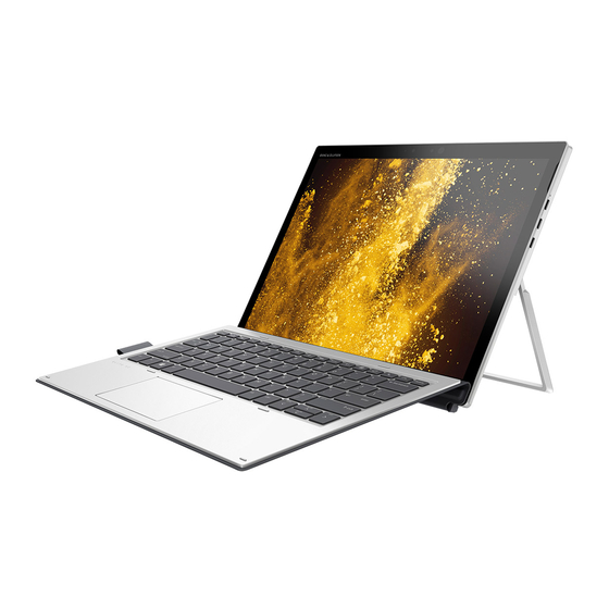
- Page 1 HP Elite x2 1013 G3 Tablet with Collaboration Keyboard Maintenance and Service Guide...
- Page 2 Intel, Core, and Pentium are U.S. registered bound by the terms of the HP End User License Not all features are available in all editions of trademarks of Intel Corporation. Microsoft and Agreement (EULA).
- Page 3 Safety warning notice WARNING! To reduce the possibility of heat-related injuries or of overheating the device, do not place the device directly on your lap or obstruct the device air vents. Use the device only on a hard, flat surface. Do not allow another hard surface, such as an adjoining optional printer, or a soft surface, such as pillows or rugs or clothing, to block airflow.
- Page 4 Safety warning notice...
-
Page 5: Table Of Contents
Table of contents 1 Product description ............................1 2 Components ..............................5 Right ..................................5 Left ..................................6 Display ..................................7 Top ..................................8 Bottom ................................... 9 Rear ..................................9 Using the kickstand ............................. 10 Keyboard area (select products only) ........................11 Connecting the keyboard ........................ - Page 6 Using HP Recovery Manager to create recovery media ..............70 Before you begin ......................70 Creating the recovery media ................... 70 Using the HP Cloud Recovery Download Tool to create recovery media .......... 71 Restoring and recovery ............................71 Restoring, resetting, and refreshing using Windows tools .............. 71 Restoring using HP Recovery Manager and the HP Recovery partition ...........
- Page 7 Using HP PC Hardware Diagnostics UEFI ......................80 Starting HP PC Hardware Diagnostics UEFI ..................81 Downloading HP PC Hardware Diagnostics UEFI to a USB flash drive ..........81 Downloading the latest HP PC Hardware Diagnostics UEFI version ......81 Downloading HP PC Hardware Diagnostics UEFI by product name or number (select products only) .....................
- Page 8 Requirements for specific countries and regions ....................87 12 Statement of memory volatility ........................89 Nonvolatile memory usage ..........................91 Questions and answers ............................93 Using HP Sure Start (select models only) ......................94 13 Recycling ..............................95 Index ................................96 viii...
-
Page 9: Product Description
Product description Category Description Product Name HP Elite x2 1013 G3 Tablet with Collaboration Keyboard Processors Intel® Core processors Intel Core i7-8650U, quad core Intel Core i7-8550U, quad core Intel Core i5-8350U, quad core Intel Core i5-8250U, quad core Intel Core i3-8130U, dual core... - Page 10 Support for Wi-Fi Specific Absorption Rates (SAR) in BIOS Compatible with Miracast-certified devices Support S3/S4 Wake on wireless LAN Supports WLAN/LAN/WWAN switching Support HP Connection Optimizer with WiFi Load balancing GPS (select models only) U-Blox GPS EVA-M8M M.2/USB WW, not available with WWAN WWAN (select models only) Huawei HP It4132, LTE/HSPA+ 4G with GPS M.2...
- Page 11 Dual accelerometers (in keyboard) Hall sensor Docking HP Thunderbolt Dock HP Thunderbolt Dock with 65W adapter supported HP Thunderbolt Dock with 90W adapter supported including Fast Charge HP Elite USB-C Docking Station BNB Universal Dock USB-C 3.1 Port Replicator Keyboard/pointing...
- Page 12 Category Description Security TPM 2.0 Pad fingerprint reader (select models only) Power-on authentication (password, fingerprint) Operating system Windows 10 Enterprise 64 Windows 10 Enterprise 64 LTSB 1607 Windows 10 Home 64 Windows 10 Home 64 Chinese Market CPPP Windows 10 Home 64 High-End Chinese Market CPPP Windows 10 Home 64 Plus Windows 10 Home 64 Plus Single Language Windows 10 Home 64 Single Language...
-
Page 13: Components
Component Description USB Type-C power connector and Connects an AC adapter that has a USB Type-C connector, supplying power to Thunderbolt port with HP Sleep the computer and, if needed, charging the computer battery. and Charge – and – Connects and charges most USB devices that have a Type-C connector, such as a cell phone, camera, activity tracker, or smartwatch, and provides high- speed data transfer. -
Page 14: Left
For additional safety information, refer to the Regulatory, Safety, and Environmental Notices. To access this guide: Select the Start button, select HP Help and Support, and ▲ then select HP Documentation. ‒ or –... -
Page 15: Display
For wireless regulatory notices, see the section of the Regulatory, Safety, and Environmental Notices that applies to your country or region. To access this guide: ▲ Select the Start button, select HP Help and Support, and then select HP Documentation. ‒ or – Select the Start button, select HP, and then select HP Documentation. ▲... -
Page 16: Top
Component Description Power light On: The computer is on. ● ● Blinking: The computer is in the Sleep state, a power- saving state. The computer shuts off power to the display and other unneeded components. ● Off: The computer is off or in Hibernation. Hibernation is a power-saving state that uses the least amount of power. -
Page 17: Bottom
Bottom Component Description Alignment post connectors (2) Connect to the alignment posts on the keyboard (select products only). Keyboard connector Connects the computer to the keyboard (select products only). Rear Component Description Rear camera Allows you to video chat, record video, and record still images. Fingerprint reader (select products only) Allows a fingerprint logon to Windows, instead of a password logon. -
Page 18: Using The Kickstand
Using the kickstand To change the angle for the display, follow these steps: Hold the tablet with top edge up (the speakers are on top). Slide the kickstand away from the tablet and position the kickstand at the desired angle. The kickstand will hold at a midway point (1) of about 52 degrees or at full stopping point (2) of about 118 degrees. -
Page 19: Keyboard Area (Select Products Only)
Keyboard area (select products only) Connecting the keyboard To connect the keyboard, lower the computer onto the keyboard until the connectors click into place. ▲ Removing the keyboard To remove the computer from the keyboard, pull the computer away from the back of the keyboard. ▲... -
Page 20: Touchpad
TouchPad Component Description TouchPad zone Reads your finger gestures to move the pointer or activate items on the screen. Left TouchPad button Functions like the left button on an external mouse. Right TouchPad button Functions like the right button on an external mouse. Chapter 2 Components... -
Page 21: Lights
Lights Component Description Caps lock light On: Caps lock is on, which switches the key input to all capital letters. Fn lock light On: The key is locked. Mute light On: Computer sound is off. ● ● Off: Computer sound is on. Microphone mute light ●... -
Page 22: Special Keys
Special keys Component Description Displays system information when pressed in combination with key. Executes frequently used system functions when pressed in combination with another key. Such key combinations are called hot keys. Windows key Opens the Start menu. NOTE: Pressing the Windows key again will close the Start menu. -
Page 23: Action Keys
Action keys An action key performs the function indicated by the icon on the key. To determine which keys are on your product, see Special keys on page To use an action key, press and hold the key. ▲ Icon Description Helps prevent side-angle viewing from onlookers. - Page 24 Icon Description Turns the screen sharing function on or off. NOTE: This feature requires Skype for Business or Lync 2013 running on Microsoft Exchange or Office 365 servers. ● Answers a call. Starts a call during a 1-on-1 chat. ● Places a call on hold.
-
Page 25: Labels
Service label—Provides important information to identify your computer. When contacting support, you ● may be asked for the serial number, the product number, or the model number. Locate this information before you contact support. Component HP product name Serial number Product ID Warranty period Regulatory label(s)—Provide(s) regulatory information about the computer. -
Page 26: Illustrated Parts Catalog
Computer major components NOTE: HP continually improves and changes product parts. For complete and current information on supported parts for your computer, go to http://partsurfer.hp.com, select your country or region, and then follow the on-screen instructions. NOTE: Details about your computer, including model, serial number, product key, and length of warranty, are on the service tag at the bottom of your computer. - Page 27 Item Component Spare part number Collaboration Travel Keyboard L29965-001 For a list of keyboard country codes, see Miscellaneous parts on page Display panel WUXGA+, privacy (includes privacy panel, touch board, IR bezel, LCD cable, and touch L31364-001 control cable) 3k2k, models without an IR camera (includes panel, touch board, bezel, LCD cable, and L31365-001 touch control cable) 3k2k, models with an IR camera (includes panel, touch board, IR bezel, LCD cable, and...
- Page 28 Item Component Spare part number Qualcomm Snapdragon X12 LTE-Advanced L29295-005 (19) Solid-state drive (M.2) (see Solid-state drive on page 1 TB, PCIe, TLC L31368-001 512 GB, PCIe, self-encrypting drive (SED), Opal 2, TLC L31366-001 512 GB, PCIe, TLC L31372-001 256 GB, PCIe, self-encrypting drive (SED), Opal 2, TLC L31369-001 256 GB, PCIe, TLC L31370-001...
-
Page 29: Plastics Kit
Plastics Kit Item Component Spare part number Plastics Kit L31374-001 Antenna holder insert Fingerprint reader insert SIM tray SIM insert SIM tray insert IR camera bezel HD camera bezel WWAN gasket, IR LED tape, USB bracket foil, speaker gasket, thermal long/short gasket, power button, volume button (not illustrated) Plastics Kit... -
Page 30: Miscellaneous Parts
710413-001 65 W, nPFC, USB-C, slim, straight, 1.8 m L04650-850 65 W, nPFC, RC, USB-C, 3 pin 860209-850 Docks HP Thunderbolt Dock 120W (with cable) L15809-001 HP Thunderbolt Dock 230W (with cable) L24855-001 HP Thunderbolt 3 Dock 849784-001 HP USB-C Universal Dock... - Page 31 Component Spare part number For use in Germany L29965-041 For use in Greece L29965-151 For use in Hungary L29965-211 For use in Iceland L29965-DD1 For use in India L29965-D61 For use internationally L29965-B31 For use in Israel L29965-BB1 For use in Italy L29965-061 For use in Japan L29965-291...
- Page 32 Component Spare part number For use in Israel L19344-001 For use in Italy L19346-001 For use in North America L19348-001 For use in the People’s Republic of China L19349-001 For use in South Africa L19350-001 For use in Taiwan L19353-001 For use in Switzerland L19351-001 For use in Thailand...
-
Page 33: Removal And Replacement Procedures Preliminary Requirements
Removal and replacement procedures preliminary requirements Tools required You will need the following tools to complete the removal and replacement procedures: Magnetic screwdriver ● Phillips PH Type #0 and #1 screwdrivers ● Torx T5 screwdriver ● Non-marking, non-magnetic pry tool ●... -
Page 34: Packaging And Transporting Guidelines
An electronic device exposed to ESD may not be affected at all and can work perfectly throughout a normal cycle. Or the device may function normally for a while, then degrade in the internal layers, reducing its life expectancy. CAUTION: To prevent damage to the tablet when you are removing or installing internal components, observe these precautions: Keep components in their electrostatic-safe containers until you are ready to install them. -
Page 35: Workstation Guidelines
Workstation guidelines Follow these grounding workstation guidelines: Cover the workstation with approved static-shielding material. ● Use a wrist strap connected to a properly grounded work surface and use properly grounded tools and ● equipment. ● Use conductive field service tools, such as cutters, screw drivers, and vacuums. ●... - Page 36 The following table lists the shielding protection provided by antistatic bags and floor mats. Material Voltage protection level Antistatic plastics Bags 1,500 V Carbon-loaded plastic Floor mats 7,500 V Metallized laminate Floor mats 5,000 V Chapter 4 Removal and replacement procedures preliminary requirements...
-
Page 37: Removal And Replacement Procedures For Customer Self-Repair Parts
Self-Repair is supported in your location. NOTE: HP continually improves and changes product parts. For complete and current information on supported parts for your computer, go to http://partsurfer.hp.com, select your country or region, and then follow the on-screen instructions. Component replacement procedures... - Page 38 Pull the sides of the kickstand away from the computer (3), and then remove the kickstand (4). Reverse this procedure to replace the kickstand. Chapter 5 Removal and replacement procedures for Customer Self-Repair parts...
-
Page 39: Removal And Replacement Procedures For Authorized Service Provider Parts
NOTE: HP continually improves and changes product parts. For complete and current information on supported parts for your computer, go to http://partsurfer.hp.com, select your country or region, and then follow the on-screen instructions. There are as many as 42 screws that must be removed, replaced, and/or loosened when servicing Authorized Service Provider only parts. -
Page 40: Nano Sim Card
Nano SIM card CAUTION: To prevent damage to the connectors, use minimal force when inserting a nano SIM card. CAUTION: To prevent damage to a SIM card or a computer, do not change the size of a SIM card by cutting or sanding the card. -
Page 41: Display Panel
Display panel Display panel Spare part number Back cover for use in models without WWAN L31357-001 Back cover for use in models with WWAN L31358-001 Display panel, WUXGA+, privacy (includes privacy panel, touch board, IR bezel, LCD cable, and touch L31364-001 control cable) Display panel, 3k2k, models without an IR camera (includes panel, touch board, bezel, LCD cable,... - Page 42 Position a suction tool at the top corner of the display panel (1), and then rotate the locking lever down to lock the cup (2). Pull the suction tool handle to disengage the panel from the computer. Chapter 6 Removal and replacement procedures for Authorized Service Provider parts...
- Page 43 Lift the panel (1), and then disconnect the battery cable (2), display cable (3), and touch cable (4) from the system board. IMPORTANT: Be careful when opening to avoid tearing cables. Be sure to open from the top. Reverse this procedure to replace the display panel. Component replacement procedures...
-
Page 44: Battery
Battery Description Spare part number Battery (4 cell, 50 Wh) 937434-855 IMPORTANT: Make special note of each screw size and location during removal and replacement. Before removing the battery, follow these steps: Turn off the computer. If you are unsure whether the computer is off or in Hibernation, turn the computer on, and then shut it down through the operating system. - Page 45 Carefully rotate the top of the battery up (1), and the lift the battery out of the computer (2). Reverse this procedure to replace the battery. Component replacement procedures...
-
Page 46: Solid-State Drive
Solid-state drive Description Spare part number 1 TB, PCIe, TLC L31368-001 512 GB, PCIe, self-encrypting drive (SED), Opal 2, TLC L31366-001 512 GB, PCIe, TLC L31372-001 256 GB, PCIe, self-encrypting drive (SED), Opal 2, TLC L31369-001 256 GB, PCIe, TLC L31370-001 256 GB, PCIe L31371-001... -
Page 47: Hall Sensor Board
Hall sensor board Description Spare part number Hall sensor board (includes cable) L31343-001 Before removing the hall effects sensor board, follow these steps: Turn off the computer. If you are unsure whether the computer is off or in Hibernation, turn the computer on, and then shut it down through the operating system. -
Page 48: Kickstand Hinges
Kickstand hinges Description Kickstand hinges L31376-001 IMPORTANT: Make special note of each screw size and location during removal and replacement. Before removing the kickstand hinges, follow these steps: Turn off the computer. If you are unsure whether the computer is off or in Hibernation, turn the computer on, and then shut it down through the operating system. -
Page 49: Wwan Module (Select Products Only)
WWAN module (select products only) Description Spare part number Huawei ME906S LTE HSPA+ L29293-005 Qualcomm Snapdragon X12 LTE-Advanced L29295-005 Before removing the WWAN module, follow these steps: Turn off the computer. If you are unsure whether the computer is off or in Hibernation, turn the computer on, and then shut it down through the operating system. - Page 50 NOTE: If the antenna cables are not connected to the terminals on the module, protective sleeves should be installed on the antenna connectors, as shown in the following illustration. Reverse this procedure to replace the WWAN module. Chapter 6 Removal and replacement procedures for Authorized Service Provider parts...
-
Page 51: Pogo Connector
POGO connector Description Spare part number POGO connector and cable L31359-001 Turn off the computer. If you are unsure whether the computer is off or in Hibernation, turn the computer on, and then shut it down through the operating system. Disconnect the power from the computer by unplugging the power cord from the computer. -
Page 52: Camera Connector Bracket
Camera connector bracket Before removing the camera connector bracket, follow these steps: Turn off the computer. If you are unsure whether the computer is off or in Hibernation, turn the computer on, and then shut it down through the operating system. Disconnect the power from the computer by unplugging the power cord from the computer. -
Page 53: Ir Camera
IR camera Description Spare part number IR camera L31350-001 IR camera bezel L31374-001 (Plastics Kit) Before removing the IR camera, follow these steps: Turn off the computer. If you are unsure whether the computer is off or in Hibernation, turn the computer on, and then shut it down through the operating system. -
Page 54: Front-Facing Hd Camera
Front-facing HD camera Description Spare part number Front-facing HD camera L31348-001 Front-facing camera bezel L31374-001 (Plastics Kit) Before removing the camera, follow these steps: Turn off the computer. If you are unsure whether the computer is off or in Hibernation, turn the computer on, and then shut it down through the operating system. -
Page 55: Rear-Facing Camera
Rear-facing camera Description Spare part number Rear-facing camera L31349-001 Before removing the camera, follow these steps: Turn off the computer. If you are unsure whether the computer is off or in Hibernation, turn the computer on, and then shut it down through the operating system. Disconnect the power from the computer by unplugging the power cord from the computer. -
Page 56: Microphone Board
Microphone board Description Spare part number Microphone board (includes ambient light sensor) L31344-001 Before removing the microphone board, follow these steps: Turn off the computer. If you are unsure whether the computer is off or in Hibernation, turn the computer on, and then shut it down through the operating system. Disconnect the power from the computer by unplugging the power cord from the computer. - Page 57 To remove the plastic bezel, remove speaker cable from the clip on the bezel (1), remove the Phillips M1.6×1.6 screw (2), and then use a tool to remove the bezel from the computer (3). Reverse this procedures to replace the microphone board. Component replacement procedures...
-
Page 58: Ir Led Module
IR LED module Description Spare part number IR LED module L31350-001 IMPORTANT: Make special note of each screw size and location during removal and replacement. Before removing the module, follow these steps: Turn off the computer. If you are unsure whether the computer is off or in Hibernation, turn the computer on, and then shut it down through the operating system. -
Page 59: System Board
System board Description Spare part number System board with integrated Intel Core i7-8650U processor and 16 GB of system memory L31341-601 System board with integrated Intel Core i7-8650U processor and 8 GB of system memory L31978-601 System board with integrated Intel Core i7-8550U processor and 16 GB of system memory L33481-601 System board with integrated Intel Core i7-8550U processor and 8 GB of system memory L31977-601... - Page 60 (3) WLAN antenna cables (4) Fan cables (5) Hall sensor board cable (6) POGO cable On models with a SIM card installed, remove the SIM tray (1). NOTE: If a SIM blank is installed, it must be removed after the system board is removed. Remove the Phillips M1.6×1.6 screw (2) that secures the volume cable, and then disconnect the cable from the system board ZIF connector (3).
- Page 61 Using a PH type #0 screwdriver, remove the Phillips M1.6×1.6 screw (8) from the left fan. Lift the heat sink up to a 90 degree angle (1). Lift the left edge of the system board (2), and then pull it away from the connectors to remove it (3). If a SIM blank is installed, remove it from the system board.
- Page 62 A BIOS board is connected to the system board as shown in the following image. DO NOT remove this board when removing the system board. Reverse this procedure to replace the system board. IMPORTANT: When installing a new system board, the thermal grease and thermal pads must be replaced. Heat sink on page 56 for more information.
-
Page 63: Antennas
Antennas Description Spare part number Antennas, WLAN and WWAN L31347-001 IMPORTANT: Be careful when lifting the antennas to avoid tearing them. When the antennas use a bumper, pull the cables up evenly. Before removing the antennas, follow these steps: Turn off the computer. If you are unsure whether the computer is off or in Hibernation, turn the computer on, and then shut it down through the operating system. -
Page 64: Heat Sink
Heat sink Description Spare part number Heat sink L31354-001 Turn off the computer. If you are unsure whether the computer is off or in Hibernation, turn the computer on, and then shut it down through the operating system. Disconnect the power from the computer by unplugging the power cord from the computer. Disconnect all external devices from the computer. - Page 65 The thermal material must be thoroughly cleaned from the surfaces of the heat sink and the system board components each time the heat sink is removed. Replacement thermal material is included with the heat sink and system board spare part kits. Thermal pads are used on the heat sink (2), (4) and system board (3).
-
Page 66: Speakers
Speakers Description Spare part number Speakers L31353-001 Before removing the speakers, follow these steps: Turn off the computer. If you are unsure whether the computer is off or in Hibernation, turn the computer on, and then shut it down through the operating system. Disconnect the power from the computer by unplugging the power cord from the computer. - Page 67 Use a tool to release the right speaker from the adhesive that secures it (3). Reverse this procedure to replace the speakers. Component replacement procedures...
-
Page 68: Fans
Fans Description Spare part number Fan Kit L31355-001 Before removing the fans, follow these steps: Turn off the computer. If you are unsure whether the computer is off or in Hibernation, turn the computer on, and then shut it down through the operating system. Disconnect the power from the computer by unplugging the power cord from the computer. - Page 69 Remove the fans from the computer (2). Reverse this procedure to replace the fans. Component replacement procedures...
-
Page 70: Power Button Board With Audio Jack Cable
Power button board with audio jack cable Description Spare part number Power button board with audio jack cable L35963-001 Before removing the power button board with audio jack cable, follow these steps: Turn off the computer. If you are unsure whether the computer is off or in Hibernation, turn the computer on, and then shut it down through the operating system. - Page 71 Use a tool to push the power button board up and out of the slot (4). Reverse this procedure to replace the power button board with audio jack cable. Component replacement procedures...
-
Page 72: Volume Board
Volume board Description Spare part number Volume board L35962-001 Before removing the volume board, follow these steps: Turn off the computer. If you are unsure whether the computer is off or in Hibernation, turn the computer on, and then shut it down through the operating system. Disconnect the power from the computer by unplugging the power cord from the computer. - Page 73 Peel the board/cable off the computer (2), and then remove the assembly from the computer (3). Reverse this procedure to replace the volume board. Component replacement procedures...
-
Page 74: Fingerprint Reader Board
Fingerprint reader board Description Spare part number Fingerprint reader board (includes bracket and cable) L31352-001 Fingerprint reader insert (for use in models without a fingerprint reader) L31374-001 (Plastics Kit) IMPORTANT: Make special note of each screw size and location during removal and replacement. Before removing the fingerprint reader board, follow these steps: Turn off the computer. - Page 75 Use a tool to lift the fingerprint reader board (3) to release it from the adhesive securing it, and then remove the fingerprint reader board. Reverse this procedure to replace the fingerprint reader board. Component replacement procedures...
-
Page 76: Cable Routing
Cable routing Use the following image to determine proper cable routing in the computer. Antenna cables (1) and speaker cables (2). ▲ Chapter 6 Removal and replacement procedures for Authorized Service Provider parts... -
Page 77: Backing Up, Restoring, And Recovering
Creating HP Recovery media (select products only) After you have successfully set up the computer, use HP Recovery Manager to create a backup of the HP Recovery partition on the computer. This backup is called HP Recovery media. In cases where the hard drive is corrupted or has been replaced, the HP Recovery media can be used to reinstall the original operating system. -
Page 78: Using Hp Recovery Manager To Create Recovery Media
On select products, you can use the HP Cloud Recovery Download Tool to create HP Recovery media on a bootable USB flash drive. For more information, see Using the HP Cloud Recovery Download Tool to create recovery media on page... -
Page 79: Using The Hp Cloud Recovery Download Tool To Create Recovery Media
Recovering using HP Recovery Manager You can use HP Recovery Manager software to recover the computer to its original factory state by using the HP Recovery media that you either created or that you obtained from HP, or by using the HP Recovery partition (select products only). -
Page 80: Recovering Using The Hp Recovery Partition (Select Products Only)
Recovering using HP Recovery media If your computer does not have an HP Recovery partition or if the hard drive is not working properly, you can use HP Recovery media to recover the original operating system and software programs that were installed at the factory. -
Page 81: Changing The Computer Boot Order
Changing the computer boot order If your computer does not restart in HP Recovery Manager, you can change the computer boot order. This is the order of devices listed in BIOS where the computer looks for startup information. You can change the selection to an optical drive or a USB flash drive, depending on the location of your HP Recovery media. -
Page 82: Computer Setup (Bios), Tpm, And Hp Sure Start
Use extreme care when making changes in Computer Setup. Errors can prevent the computer from operating properly. Starting Computer Setup ● Computers or tablets with keyboards: Turn on or restart the computer, and when the HP logo appears,q press to enter Computer ▲ Setup. Computers or tablets without keyboards: ●... -
Page 83: Navigating And Selecting In Computer Setup
Navigating and selecting in Computer Setup ● To select a menu or a menu item, use the key and the keyboard arrow keys and then press enter, or use a pointing device to select the item. NOTE: On tablets without keyboards, you can use your finger to make selections. ●... -
Page 84: Updating The Bios
Do not shut down the computer or initiate Sleep. Do not insert, remove, connect, or disconnect any device, cable, or cord. Type support in the taskbar search box, and then select the HP Support Assistant app. – or – Select the question mark icon in the taskbar. -
Page 85: Changing The Boot Order Using The F9 Prompt
For any compliance issues arising from your operation/usage of TPM which violates the above mentioned requirement, you shall bear all the liabilities wholly and solely. HP will not be responsible for any related liabilities. -
Page 86: Using Hp Sure Start (Select Products Only)
If the BIOS becomes corrupted or is attacked, HP Sure Start automatically restores the BIOS to its previously safe state, without user intervention. HP Sure Start is configured and already enabled so that most users can use the HP Sure Start default configuration. The default configuration can be customized by advanced users. -
Page 87: Using Hp Pc Hardware Diagnostics
The tool runs within the Windows operating system in order to diagnose hardware failures. If HP PC Hardware Diagnostics Windows is not installed on your computer, first you must download and install it. To download HP PC Hardware Diagnostics Windows, see... -
Page 88: Downloading The Latest Hp Pc Hardware Diagnostics Windows Version
If your PC will not boot into Windows, you can use HP PC Hardware Diagnostics UEFI to diagnose hardware issues. -
Page 89: Starting Hp Pc Hardware Diagnostics Uefi
Downloading HP PC Hardware Diagnostics UEFI to a USB flash drive Downloading HP PC Hardware Diagnostics UEFI to a USB flash drive can be useful in the following situations: HP PC Hardware Diagnostics UEFI is not included in the preinstall image. -
Page 90: Using Remote Hp Pc Hardware Diagnostics Uefi Settings (Select Products Only)
Find out more. Downloading Remote HP PC Hardware Diagnostics UEFI NOTE: HP Remote PC Hardware Diagnostics UEFI is also available as a Softpaq that can be downloaded to a server. Downloading the latest Remote HP PC Hardware Diagnostics UEFI version To download the latest Remote HP PC Hardware Diagnostics UEFI version, follow these steps: Go to http://www.hp.com/go/techcenter/pcdiags. - Page 91 Make your customization selections. Select Main, and then Save Changes and Exit to save your settings. Your changes take effect when the computer restarts. Using Remote HP PC Hardware Diagnostics UEFI settings (select products only)
-
Page 92: 10 Specifications
10 Specifications Computer specifications Tablet Keyboard Tablet and Keyboard Dimensions Width 300.0 mm (11.81 in) 300.0 mm (11.81 in) 300.0 mm (11.81 in) Depth 217.25 mm (8.55 in) 231.5 mm (9.11 in) 231.5 mm (8.65 in) Height 7.9 mm (0.31 in) 4.9 mm (0.19 in) 13.3 mm (0.52 in) Weight... -
Page 93: Display Specifications
Display specifications Item Value Active diagonal size 13.0" (33.02 cm) Brightness 72% CG; 450 nits Pixel resolution 3000 × 2000 (3k×2k+) 1920 x 1280 (WUXGA+) Surface treatment 3k×2k+: BrightView WUXGA+: anti glare Interface eDP 1.4+PSR Backlight WLED Viewing angle UWVA 85/85/85/85 (Left/Right/Down/Up) Display specifications... -
Page 94: 11 Power Cord Set Requirements
11 Power cord set requirements The wide-range input feature of the computer permits it to operate from any line voltage from 100 to 120 V ac, or from 220 to 240 V ac. The 3-conductor power cord set included with the computer meets the requirements for use in the country or region where the equipment is purchased. -
Page 95: Requirements For Specific Countries And Regions
Requirements for specific countries and regions Country/region Accredited agency Applicable note number Argentina IRAM Australia Austria Belgium CEBEC Brazil ABNT Canada Chile Denmark DEMKO Finland FIMKO France Germany India Israel Italy Japan The Netherlands KEMA New Zealand SANZ Norway NEMKO The People's Republic of China Saudi Arabia SASO... - Page 96 Country/region Accredited agency Applicable note number The appliance coupler, flexible cord, and wall plug must bear a “T” mark and registration number in accordance with the Japanese Dentori Law. The flexible cord must be Type VCTF, 3-conductor, 0.75 mm² or 1.25 mm² conductor size. The wall plug must be a two-pole grounding type with a Japanese Industrial Standard C8303 (7 A, 125 V ac) configuration.
-
Page 97: 12 Statement Of Memory Volatility
Intel-based and AMD-based system boards contain nonvolatile memory subcomponents as originally shipped from HP, assuming that no subsequent modifications have been made to the system and assuming that no applications, features, or functionality have been added to or installed on the system. - Page 98 If a DriveLock password is set, select the Security menu, and scroll down to Hard Drive Utilities under the Utilities menu. Select Hard Drive Utilities, select DriveLock, then uncheck the checkbox for DriveLock password on restart. Select OK to proceed. Select the Main menu, and then select Reset BIOS Security to factory default.
-
Page 99: Nonvolatile Memory Usage
HP Sure Start only) backup of The content is managed Embedded Controller. critical System solely by the HP Sure Start BIOS code, EC Embedded Controller. firmware, and critical computer configuration data for select... - Page 100 512 KByte flash Stores Fingerprint reader memory is Only a digitally signed (select products fingerprint programmed by user application can make the only) templates. enrollment in HP call to write to the flash. ProtectTools Security Manager. Chapter 12 Statement of memory volatility...
-
Page 101: Questions And Answers
HP has provided options in Computer Setup (BIOS) to allow you to run in legacy BIOS, if required by the operating system. Examples of this requirement would be if you upgrade or downgrade the OS. -
Page 102: Using Hp Sure Start (Select Models Only)
BIOS to its previously safe state, without user intervention. Those select computer models ship with HP Sure Start configured and enabled. HP Sure Start is configured and already enabled so that most users can use the HP Sure Start default configuration. The default configuration can be customized by advanced users. -
Page 103: 13 Recycling
Follow the local laws and regulations in your area for battery disposal. HP encourages customers to recycle used electronic hardware, HP original print cartridges, and rechargeable batteries. For more information about recycling programs, see the HP Web site at http://www.hp.com/recycle. -
Page 104: Index
Index duck head, spare part number 24 AC adapter, spare part numbers 22 cable routing 68 action keys 15 call answer light 13 electrostatic discharge 25 identifying 15 call end light 13 embedded numeric keypad, keyboard backlight 15 camera 7 identifying 14 mute 15 front-facing HD 46... - Page 105 4 microphone mute 15 spare part number 20 original system recovery 71 HP PC Hardware Diagnostics UEFI kickstand bracket downloading 81 spare part numbers 20 starting 81 kickstand, identifying 9 packaging guidelines 26...
- Page 106 69 security cable slot, identifying 6 wireless 2 security, product description 4 product name 1 sensors Thunderbolt port with HP Sleep and product name and number, product description 3 Charge computer 17 serial number, computer 17...
- Page 107 Windows tools, using 69 wireless action key 15 wireless antennas, identifying 7 wireless certification label 17 wireless light, identifying 13 wireless, product description 2 WLAN antennas, identifying 7 WLAN device 17 WLAN label 17 workstation guidelines 27 WWAN spare part number 19 WWAN antennas, identifying 7 WWAN module 41 spare part numbers 19, 41...
Need help?
Do you have a question about the Elite x2 1013 G3 and is the answer not in the manual?
Questions and answers