
Related Manuals for HP ELITE x2 1012 G1


Summary of Contents for HP ELITE x2 1012 G1
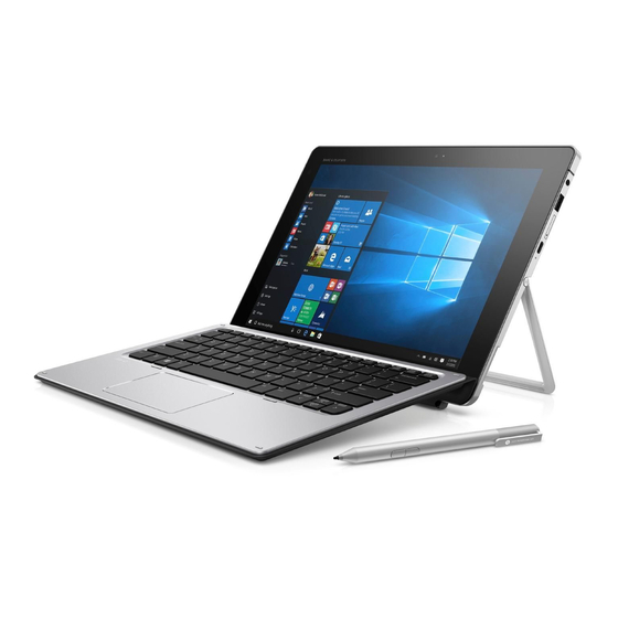
- Page 1 HP Elite x2 1012 G1 Tablet HP Elite x2 1012 G1 Tablet with Advanced Keyboard HP Elite x2 1012 G1 Tablet with Travel Keyboard Maintenance and Service Guide IMPORTANT! This document is intended for HP authorized service providers only.
- Page 2 The information contained herein is subject to change without notice. The only warranties for HP products and services are set forth in the express warranty statements accompanying such products and services. Nothing herein should be construed as constituting an additional warranty.
- Page 3 Safety warning notice WARNING! To reduce the possibility of heat-related injuries or of overheating the device, do not place the device directly on your lap or obstruct the device air vents. Use the device only on a hard, flat surface. Do not allow another hard surface, such as an adjoining optional printer, or a soft surface, such as pillows or rugs or clothing, to block airflow.
- Page 4 Safety warning notice...
-
Page 5: Table Of Contents
Table of contents 1 Product description ............................1 2 External component identification ........................5 Tablet edge components ............................5 Display ..................................8 Back ..................................9 Using the kickstand ............................. 10 Keyboard base components (select products only) .................... 11 TouchPad ............................11 Lights .............................. - Page 6 Using HP Recovery media to recover ................63 Changing the boot order ....................63 Removing the HP Recovery partition (select products only) ......... 64 7 Computer Setup (BIOS), TPM, and HP Sure Start ..................... 65 Using Computer Setup ............................65 Starting Computer Setup ........................65 Navigating and selecting in Computer Setup ...................
- Page 7 8 Using HP PC Hardware Diagnostics (UEFI) ....................... 70 Downloading HP PC Hardware Diagnostics (UEFI) to a USB device ..............70 9 Specifications .............................. 72 Computer specifications ............................72 Display specifications ............................73 Solid-state drive specifications ........................... 73 Memory specifications ............................73 10 Power cord set requirements ........................
- Page 8 viii...
-
Page 9: Product Description
Keyboard Advanced Keyboard Product Name HP Elite x2 1012 G1 Tablet √ HP Elite x2 1012 G1 Travel Keyboard √ HP Elite x2 1012 G1 Advanced Keyboard √ Chipset Intel Skylake Premium PCH (integrated with CPU) Graphics Internal graphics:... - Page 10 Category Description 1012 1012 1012 Tablet tablet with tablet Travel with Keyboard Advanced Keyboard Wireless WLAN: WLAN options via M.2: Intel® 802.11 2x2ac + BT 4.1 Combo (non-vPro)- Snowfield Peak 8260 Intel® 802.11 2x2ac + BT 4.1 Combo Snowfield Peak 8260 Intel®...
- Page 11 Category Description 1012 1012 1012 Tablet tablet with tablet Travel with Keyboard Advanced Keyboard Power Battery requirements Slate: 4-cell Long Life Polymer 40 Whr (2.86Ahr) Base: None AC adapter: (USB Type-C) 45W "Smart" AC Adapter non-PFC USB-C Power Cord, localized Duckhead for use in United States and South Korea Duckhead Power Cord for use in all countries except South Korea Security...
- Page 12 Category Description 1012 1012 1012 Tablet tablet with tablet Travel with Keyboard Advanced Keyboard Windows 8.1 Emerging Markets 64 Windows 8.1 Multi-Language 64 Windows 8.1 Professional 64 Serviceability End user replaceable parts: AC Adapter: Slate only Active Pen (select products only) Chapter 1 Product description...
-
Page 13: External Component Identification
External component identification Tablet edge components Component Description Speakers Produce sound. Internal microphones Record sound. Audio-out (headphone)/Audio-in (microphone) Connects optional powered stereo speakers, headphones, combo jack earbuds, a headset, or a television audio cable. Also connects an optional headset microphone. This jack does not support optional microphone-only devices. - Page 14 Regulatory, Safety and Environmental Notices. To access this guide: ▲ Select the Start button, select All apps, select HP Help and Support, and then select HP Documentation. NOTE: When a device is connected to the jack, the tablet speakers are disabled.
- Page 15 Component Description ● When the tablet is in the Sleep state, press the button briefly to exit Sleep. CAUTION: Pressing and holding down the power button results in the loss of unsaved information. NOTE: Although you can turn off the tablet with the power button, the recommended procedure is to use the Windows Shut down command.
-
Page 16: Display
For wireless regulatory notices, see the section of the Regulatory, Safety, and Environmental Notices that applies to your country or region. To access this guide: Select the Start button, select All apps, select HP Help and Support, and then select HP Documentation. ▲ Chapter 2 External component identification... -
Page 17: Back
Back Component Description Camera flash Provides a camera flash. You can control the flash using the Windows Metro Camera app. Webcam (rear) Records video and captures photographs. Some products allow you to video conference and chat online using streaming video. Fingerprint reader (select products Allows a fingerprint logon to Windows, instead of a password logon. -
Page 18: Using The Kickstand
Using the kickstand To change the angle for the display, follow these steps: Hold the tablet with top edge up (the speakers are on top). Slide the kickstand away from the tablet and position the kickstand at the desired angle. The kickstand will hold at a midway point (1) of about 52 degrees or at full stopping point (2) of about 118 degrees. -
Page 19: Keyboard Base Components (Select Products Only)
Keyboard base components (select products only) Your tablet supports an optional keyboard. This section provides information about the common features of the supported keyboards. NOTE: Keyboard appearance and features might vary. TouchPad Component Description TouchPad on/off button Turns the TouchPad on and off. TouchPad light ●... -
Page 20: Lights
Lights Component Description Caps lock light ● On: Caps lock is on, which switches the keys to all capital letters. TouchPad light ● On: The TouchPad is off. ● Off: The TouchPad is on. Mute light ● Amber: Sound is off. ●... -
Page 21: Special Function Keys
Special function keys Component Description Displays system information when pressed in combination with key. Executes frequently used system functions when pressed in combination with a function key, the num lock key, or the key. Windows key Opens the Start menu. NOTE: Pressing the Windows key again will close the Start menu. -
Page 22: Using The Hot Keys
Using the hot keys To use a hot key: ▲ Press the key, and then press the correct function key represented by the icons below. Press fn+function key Description Initiates Sleep, which saves your information in system memory. The display and other system components turn off and power is conserved. -
Page 23: Nfc And Smart Card (Select Products Only)
For wireless regulatory notices, see the section of the Regulatory, Safety, and Environmental Notices that applies to your country or region. To access this guide: Select the Start button, select All apps, select HP Help and Support, and then select HP Documentation. ▲ Keyboard base components (select products only) -
Page 24: Connecting The Tablet To The Keyboard Base
Connecting the tablet to the keyboard base To connect the tablet to the keyboard base, follow these steps: Insert the tablet POGO pin connector docking port into the keyboard base POGO pin docking connector. Position the kickstand at the desired angle. NOTE: If you close the kickstand, you can leave the keyboard attached and position the keyboard behind the tablet. -
Page 25: Removing The Keyboard Base From The Tablet
Removing the keyboard base from the tablet To remove the keyboard base from the tablet, pull the keyboard away from the tablet. Locating system information The labels affixed to the tablet provide information you may need when you troubleshoot system problems or travel internationally with the tablet. - Page 26 Component Model name (select products only) Product number Serial number Warranty period ● Regulatory label(s)—Provide(s) regulatory information about the tablet. ● Wireless certification label(s)—Provide(s) information about optional wireless devices and the approval markings for the countries or regions in which the devices have been approved for use. Chapter 2 External component identification...
-
Page 27: Illustrated Parts Catalog
Computer major components NOTE: HP continually improves and changes product parts. For complete and current information on supported parts for your computer, go to http://partsurfer.hp.com, select your country or region, and then follow the on-screen instructions. NOTE: Details about your computer, including model, serial number, product key, and length of warranty, are on the service tag at the bottom of your computer. - Page 28 Item Component Spare part number MU736 HS3110 HSPA+ w/GPS M.s 822828-001 WWAN antenna 844870-001 Rear webcam 844883-001 WLAN module WIGIG Module W/Bracket W/Cable 844884-001 11ac 2x2 INT 8260NGW SnfP2 806721-001 11ac 2x2 INT 8260NGW SnfP2NV 806722-001 INT 802.11AC 18260+BT4 2x2 810814-005 WLAN antenna 844869-001...
-
Page 29: Miscellaneous Parts
45W adapter NPFC SMART WallMnt USB-C 828769-001 HP USB-C to DisplayPort Adapter 831753-001 HP USB-C to HDMI Adapter 831752-001 HP USB-C to USB 3.0 Adapter 814618-001 HP USB-C to VGA Adapter 831751-001 Keyboard (See Keyboard (select products only) on page 29 for a detailed list of country codes.) - Page 30 For use in Switzerland 213354-010 For use in Taiwan 393313-005 For use in Thailand 285096-009 For use in the United Kingdom 213351-010 HP Active Pen with App Launch (selct products only) 846410-001 Screw Kit 844880-001 Chapter 3 Illustrated parts catalog...
-
Page 31: Removal And Replacement Procedures Preliminary Requirements
Removal and replacement procedures preliminary requirements Tools required You will need the following tools to complete the removal and replacement procedures: Flat-bladed screwdriver ● ● Magnetic screwdriver Phillips P0 and P1 screwdrivers ● Service considerations The following sections include some of the considerations that you must keep in mind during disassembly and assembly procedures. -
Page 32: Cables And Connectors
Cables and connectors CAUTION: When servicing the computer, be sure that cables are placed in their proper locations during the reassembly process. Improper cable placement can damage the computer. Cables must be handled with extreme care to avoid damage. Apply only the tension required to unseat or seat the cables during removal and insertion. -
Page 33: Grounding Guidelines
Grounding guidelines Electrostatic discharge damage Electronic components are sensitive to electrostatic discharge (ESD). Circuitry design and structure determine the degree of sensitivity. Networks built into many integrated circuits provide some protection, but in many cases, ESD contains enough power to alter device parameters or melt silicon junctions. A discharge of static electricity from a finger or other conductor can destroy static-sensitive devices or microcircuitry. -
Page 34: Packaging And Transporting Guidelines
Packaging and transporting guidelines Follow these grounding guidelines when packaging and transporting equipment: To avoid hand contact, transport products in static-safe tubes, bags, or boxes. ● ● Protect ESD-sensitive parts and assemblies with conductive or approved containers or packaging. ● Keep ESD-sensitive parts in their containers until the parts arrive at static-free workstations. -
Page 35: Equipment Guidelines
Equipment guidelines Grounding equipment must include either a wrist strap or a foot strap at a grounded workstation. When seated, wear a wrist strap connected to a grounded system. Wrist straps are flexible straps with a ● minimum of one megohm ±10% resistance in the ground cords. To provide proper ground, wear a strap snugly against the skin at all times. -
Page 36: Removal And Replacement Procedures For Authorized Service Provider Parts
NOTE: HP continually improves and changes product parts. For complete and current information on supported parts for your computer, go to http://partsurfer.hp.com, select your country or region, and then follow the on-screen instructions. There are as many as 32 screws that must be removed, replaced, and/or loosened when servicing Authorized Service Provider only parts. -
Page 37: Keyboard (Select Products Only)
Keyboard (select products only) Description Spare part number Keyboard base with TouchPad 846748-001 Advanced Keyboard base 850487-001 For use in country Spare part For use in country Spare part For use in country Spare part or region number or region number or region number... -
Page 38: Back Cover
Back cover Description Spare part number Back cover 844871-001 IMPORTANT: Make special note of each screw and screw lock size and location during removal and replacement. Before removing the back cover, follow these steps: Turn off the computer. If you are unsure whether the computer is off or in Hibernation, turn the computer on, and then shut it down through the operating system. -
Page 39: Display Panel
Display panel Description Spare part number Panel 844861-001 Display Cable Kit 844872-001 IMPORTANT: Make special note of each screw and screw lock size and location during removal and replacement. Before removing the display panel, follow these steps: Turn off the computer. If you are unsure whether the computer is off or in Hibernation, turn the computer on, and then shut it down through the operating system. - Page 40 Disconnect the touch board cable (1) and the display cable (2), and then remove the display panel (3). Reverse this procedure to replace the display panel. Chapter 5 Removal and replacement procedures for Authorized Service Provider parts...
-
Page 41: Touch Controller Board
Touch controller board IMPORTANT: Make special note of each screw and screw lock size and location during removal and replacement. Description Spare part number Touch controller board 844861-001 Before removing the touch controller board, follow these steps: Turn off the computer. If you are unsure whether the computer is off or in Hibernation, turn the computer on, and then shut it down through the operating system. -
Page 42: Wlan Module
WLAN module IMPORTANT: Make special note of each screw and screw lock size and location during removal and replacement. Description Spare part number WLAN module WIGIG Module W/Bracket W/Cable 844884-001 11ac 2x2 INT 8260NGW SnfP2 806721-001 11ac 2x2 INT 8260NGW SnfP2NV 806722-001 INT 802.11AC 18260+BT4 2x2 810814-005... - Page 43 Reverse this procedure to replace the WLAN module. Component replacement procedures...
-
Page 44: Wwan Module (Select Products Only)
WWAN module (select products only) IMPORTANT: Make special note of each screw and screw lock size and location during removal and replacement. Description Spare part number WWAN module (select products only) UMA graphics M3-6Y30 4GBx2 1012 G1 with Windows operating system 844858-601 UMA graphics M3-6Y30 4GB fWWANx2 1012 G1 with Windows operating system and WWAN capability 845470-601... - Page 45 Reverse this procedure to replace the WWAN module (select products only). Component replacement procedures...
-
Page 46: Solid-State Drive
Solid-state drive Description Spare part number Solid-state drive 128 GB SATA-3 TLC 844862-001 180 GB SATA-3 TLC 844863-001 180 GB SATA-3 self-encrypting drive OPAL2 844864-001 256 GB SATA-3 TLC 844865-001 256 GB SATA-3 self-encrypting drive OPAL2 844866-001 256 GB PCIe-3x4 NVMe 844868-001 512 GB SATA-3 TLC 844867-001... - Page 47 Slide the solid-state drive (2) to the right, and then lift the solid-state drive to remove it. Reverse this procedure to replace the solid-state drive. Component replacement procedures...
-
Page 48: Kickstand
Kickstand Description Kickstand (included with Back cover spare part kit, 844871-001 (see Back cover on page 30). IMPORTANT: Make special note of each screw and screw lock size and location during removal and replacement. Before removing the display panel, follow these steps: Turn off the computer. - Page 49 Lift the kickstand to remove it. Reverse this procedure to replace the kickstand. Component replacement procedures...
-
Page 50: Battery
Battery Description Spare part number 4-cell Long Life Polymer 40 Whr (2.86Ahr) Battery 812205-001 IMPORTANT: Make special note of each screw and screw lock size and location during removal and replacement. Before removing the display panel, follow these steps: Turn off the computer. If you are unsure whether the computer is off or in Hibernation, turn the computer on, and then shut it down through the operating system. - Page 51 Disconnect the battery cable (3), and then lift the battery (4) to remove it. Reverse this procedure to replace the battery. Component replacement procedures...
-
Page 52: Microphone Board
Microphone board Description Spare part number Microphone board 844878-001 IMPORTANT: Make special note of each screw and screw lock size and location during removal and replacement. Before removing the display panel, follow these steps: Turn off the computer. If you are unsure whether the computer is off or in Hibernation, turn the computer on, and then shut it down through the operating system. - Page 53 Reverse this procedure to replace the microphone board. Component replacement procedures...
-
Page 54: Rear Webcam
Rear webcam Description Spare part number Rear webcam 844883-001 IMPORTANT: Make special note of each screw and screw lock size and location during removal and replacement. Before removing the display panel, follow these steps: Turn off the computer. If you are unsure whether the computer is off or in Hibernation, turn the computer on, and then shut it down through the operating system. -
Page 55: Front Webcam
Front webcam Description Spare part number Front webcam 844882-001 IMPORTANT: Make special note of each screw and screw lock size and location during removal and replacement. Before removing the display panel, follow these steps: Turn off the computer. If you are unsure whether the computer is off or in Hibernation, turn the computer on, and then shut it down through the operating system. -
Page 56: Usb Type-C Bracket
USB Type-C bracket Description USB type-C bracket (included with System Board. See System board on page 50). IMPORTANT: Make special note of each screw and screw lock size and location during removal and replacement. Before removing the display panel, follow these steps: Turn off the computer. - Page 57 Reverse this procedure to replace the USB type-C bracket. Component replacement procedures...
-
Page 58: System Board
System board Description Spare part number System board UMA graphics M3-6Y30 4GBx2 1012 G1 with Windows operating system 844858-601 UMA graphics M3-6Y30 4GB fWWANx2 1012 G1 with Windows operating system and WWAN capability 845470-601 UMA graphics M5-6Y54 4GBx2 1012 G1 with Windows operating system 845483-601 UMA graphics M5-6Y54 4GBx2 1012 G1 with Windows operating system and WWAN capability 845484-601... - Page 59 Disconnect fingerprint reader cable (4). Remove 7 Phillips M1.6x3.screws (1), and then lift the system board to remove it (2). Reverse this procedure to replace the system board. Component replacement procedures...
-
Page 60: Button Board
Button board Description Spare part number Button board For products with WWAN capability 844876-001 For products without WWAN capability 848827-001 IMPORTANT: Make special note of each screw and screw lock size and location during removal and replacement. Before removing the display panel, follow these steps: Turn off the computer. - Page 61 Reverse this procedure to replace the button board. Component replacement procedures...
-
Page 62: Fingerprint Reader Board
Fingerprint reader board Description Spare part number Fingerprint reader board (includes cable) 844875-001 IMPORTANT: Make special note of each screw and screw lock size and location during removal and replacement. Before removing the display panel, follow these steps: Turn off the computer. If you are unsure whether the computer is off or in Hibernation, turn the computer on, and then shut it down through the operating system. - Page 63 Reverse this procedure to replace the fingerprint reader board. Component replacement procedures...
-
Page 64: Pogo Connector
POGO connector Description Spare part number POGO connector 844877-001 IMPORTANT: Make special note of each screw and screw lock size and location during removal and replacement. Before removing the display panel, follow these steps: Turn off the computer. If you are unsure whether the computer is off or in Hibernation, turn the computer on, and then shut it down through the operating system. - Page 65 Release the cable, which is secured with tape, and lift the cable and connector to remove them (2). Reverse this procedure to replace the POGO connector. Component replacement procedures...
-
Page 66: Speaker
Speaker Description Spare part number Speaker 844881-001 IMPORTANT: Make special note of each screw and screw lock size and location during removal and replacement Before removing the display panel, follow these steps: Turn off the computer. If you are unsure whether the computer is off or in Hibernation, turn the computer on, and then shut it down through the operating system. - Page 67 Use a nylon pry tool carefully to release the speaker/antenna assembly (2). Reverse this procedure to replace the speaker. Component replacement procedures...
-
Page 68: Backup And Recovery
Use HP Recovery Manager to create HP Recovery media after you successfully set up the tablet. This ● step creates a backup of the HP Recovery partition on the tablet. The backup can be used to reinstall the original operating system in cases where the hard drive is corrupted or has been replaced. For... -
Page 69: Using Windows Tools
HP Recovery media can also be used to customize the system or restore the factory image if you replace the hard drive. -
Page 70: Restore And Recovery
Creating HP Recovery media (select products only) on page ● If your tablet does not allow the creation of HP Recovery media or if the HP Recovery media does not work, you can obtain recovery media for your system from support. See the Worldwide Telephone Numbers booklet included with the tablet. -
Page 71: Using The Hp Recovery Partition (Select Products Only)
Changing the boot order If your tablet does not restart in HP Recovery Manager, you can change the boot order, which is the order of devices listed in BIOS where the tablet looks for startup information. You can change the selection to an optical drive or a USB flash drive. -
Page 72: Removing The Hp Recovery Partition (Select Products Only)
Follow the on-screen instructions. Removing the HP Recovery partition (select products only) HP Recovery Manager software allows you to remove the HP Recovery partition to free up hard drive space. IMPORTANT: After you remove the HP Recovery partition, you will not be able to perform System Recovery or create HP recovery media from the HP Recovery partition. -
Page 73: Computer Setup (Bios), Tpm, And Hp Sure Start
To start Computer Setup, follow these steps: ▲ Start Computer Setup. ● Tablets with keyboards: ▲ Turn on or restart the tablet, and when the HP logo appears, press to enter Computer Setup. Tablets without keyboards: ● ▲ Turn off the tablet. Press the power button in combination with the volume down button until the Startup menu is displayed, and then tap F10 to enter Computer Setup. -
Page 74: Restoring Factory Settings In Computer Setup
Select Main, select Save Changes and Exit, and then press enter. Your changes go into effect when the tablet restarts. NOTE: Your password settings and security settings are not changed when you restore the factory settings. Chapter 7 Computer Setup (BIOS), TPM, and HP Sure Start... -
Page 75: Updating The Bios
Do not shut down the tablet or initiate Sleep. Do not insert, remove, connect, or disconnect any device, cable, or cord. Type support in the taskbar search box, and then select the HP Support Assistant app. – or – Select the question mark icon in the taskbar. -
Page 76: Changing The Boot Order Using The F9 Prompt
For any compliance issues arising from your operation/usage of TPM which violates the above mentioned requirement, you shall bear all the liabilities wholly and solely. HP will not be responsible for any related liabilities. -
Page 77: Using Hp Sure Start (Select Products Only)
If the BIOS becomes corrupted or is attacked, HP Sure Start automatically restores the BIOS to its previously safe state, without user intervention. HP Sure Start is configured and already enabled so that most users can use the HP Sure Start default configuration. The default configuration can be customized by advanced users. -
Page 78: Using Hp Pc Hardware Diagnostics (Uefi)
Using HP PC Hardware Diagnostics (UEFI) HP PC Hardware Diagnostics is a Unified Extensible Firmware Interface (UEFI) that allows you to run diagnostic tests to determine whether the computer hardware is functioning properly. The tool runs outside the operating system so that it can isolate hardware failures from issues that are caused by the operating system or other software components. - Page 79 Download any version of UEFI for a specific product Go to http://www.hp.com/support, and then select your country. The HP Support page is displayed. Select Software and Drivers. Use the categories listed to find your product. – or – Select Find Now to let HP automatically detect your product.
-
Page 80: Specifications
Specifications Computer specifications Slate Slate and Thin Slate and Productivity Keyboard Keyboard Input power Dimensions Width 300.0mm (11.81") 300.0mm (11.81") 300.0mm (11.81") Depth 213.85mm (8.42") 213.85mm (8.42") 213.85mm (8.42") Height (front to back) 8.05mm (0.32") 13.45mm (0.53") 16.45mm (0.65") Weight 1.81lb (820g) 2.67 lb (1210 g) 2.87 lb (1302 g) -
Page 81: Display Specifications
Display specifications Internal Touch screen 12.0" diagonal LED-backlit BV UWVA eDP 1.3 Ultra-slim (1920 x 1280 – Full HD*) Touch screenChemically-strengthened Corning® Gorilla® Glass 4 top cover directly bonded to display Brightness 200 nits 340 nits (typical) Pixel resolution Format 1920 x 1280 (WUXGA+) Configuration RGB stripe... - Page 82 Memory 8GB Total System Memory Maximum Up to 8 GB Chapter 9 Specifications...
-
Page 83: 10 Power Cord Set Requirements
10 Power cord set requirements The wide-range input feature of the computer permits it to operate from any line voltage from 100 to 120 volts AC, or from 220 to 240 volts AC. The 3-conductor power cord set included with the computer meets the requirements for use in the country or region where the equipment is purchased. - Page 84 Country/region Accredited agency Applicable note number Sweden SEMKO Switzerland Taiwan BSMI The United Kingdom The United States The flexible cord must be Type HO5VV-F, 3-conductor, 1.0-mm² conductor size. Power cord set fittings (appliance coupler and wall plug) must bear the certification mark of the agency responsible for evaluation in the country or region where it will be used.
-
Page 85: 11 Statement Of Memory Volatility
Following system shutdown and removal of all power sources from an HP Business PC system, personal data can remain on volatile system memory (DIMMs) for a finite period of time and will also remain in nonvolatile memory. - Page 86 If a DriveLock password is set, select the Security menu, and scroll down to Hard Drive Utilities under the Utilities menu. Select Hard Drive Utilities, select DriveLock, then uncheck the checkbox for DriveLock password on restart. Select OK to proceed. Select the Main menu, and then select Reset BIOS Security to factory default.
- Page 87 NOTE: If the system has a BIOS administrator password, enter the password at the prompt. Select Main, select Restore Defaults, and then select Yes to load defaults. Select the Security menu, select Restore Security Level Defaults, and then select Yes to restore security level defaults.
- Page 88 NOTE: The amount of time it takes for Disk Sanitizer to run can take several hours. Plug the computer into an AC outlet before starting. Turn on or restart the computer, and then press while the “Press the ESC key for Startup Menu” message is displayed at the bottom of the screen.
-
Page 89: Nonvolatile Memory Usage
HP Sure Start only) backup of The content is managed Embedded Controller. critical System solely by the HP Sure Start BIOS code, EC Embedded Controller. firmware, and critical PC configuration data for select... - Page 90 Fingerprint reader 512 KByte flash Stores Fingerprint reader memory is Only a digitally signed fingerprint programmed by user application can make the templates. enrollment in HP call to write to the flash. ProtectTools Security Manager. Chapter 11 Statement of memory volatility...
-
Page 91: Questions And Answers
HP has provided options in Computer Setup (BIOS) to allow you to run in legacy BIOS, if required by the operating system. Examples of this requirement would be if you upgrade or downgrade the OS. -
Page 92: Using Hp Sure Start (Select Models Only)
BIOS to its previously safe state, without user intervention. Those select computer models ship with HP Sure Start configured and enabled. HP Sure Start is configured and already enabled so that most users can use the HP Sure Start default configuration. The default configuration can be customized by advanced users. -
Page 93: 12 Recycling
When a non-rechargeable or rechargeable battery has reached the end of its useful life, do not dispose of the battery in general household waste. Follow the local laws and regulations in your area for battery disposal. HP encourages customers to recycle used electronic hardware, HP original print cartridges, and rechargeable batteries. -
Page 94: Index
9 using 14 spare part number 21 display 8 HP Active Pen spare part numbers 40 keyboard base 11 spare part number 22 kickstand, identifying 9 kickstand 10 HP PC Hardware Diagnostics (UEFI) computer major components 19 using 70 Index... - Page 95 USB 65 spare part number 21 USB flash drive 63 lights POGO connector 56 using HP Recovery media 61 AC adapter and battery light 6 spare part numbers 21, 56 recovery media microphone mute 12 POGO pin connector, identifying 6...
- Page 96 spare part numbers 20, 38 specifications 73 webcam 8 speaker 58 front 47 spare part number 21 identifying 9 spare part numbers 58 rear 46 speakers spare part numbers 46, 47 identifying 5 webcam light, identifying 8 specifications webcam, identifying 8 computer 72 WiGig antenna, identifying 8 display 73...
Need help?
Do you have a question about the ELITE x2 1012 G1 and is the answer not in the manual?
Questions and answers