Burkert 3323 Quick Start Manual
Electromotive diaphragm valve
Hide thumbs
Also See for 3323:
- Operating instructions manual (130 pages) ,
- Quick start manual (44 pages) ,
- Operating instructions manual (122 pages)

Related Manuals for Burkert 3323


Summary of Contents for Burkert 3323
- Page 1 Type 3323, 3324, 3325 AE3323, AE3324, AE3325 Electromotive diaphragm valve Elektromotorisches Membranventil Vanne à membrane électromotorisée Quickstart English Deutsch Français...
- Page 2 We reserve the right to make technical changes without notice. Technische Änderungen vorbehalten. Sous réserve de modifications techniques. © 2016 - 2018 Bürkert Werke GmbH & Co. KG Operating Instructions 1810/02_EU-ML_00810539 / Original DE...
-
Page 3: Table Of Contents
Type 3323, 3324, 3325 Contents 7.3 Installation of devices with welded connection ..18 THE QUICKSTART ..............5 7.4 Following installation ..........23 1.1 Definitions of terms ............. 5 7.5 Rotating the actuator ..........23 1.2 Symbols ............... 5 7.6 Holding device ............24 INTENDED USE ..............6 ELECTRICAL INSTALLATION ..........24 BASIC SAFETY INSTRUCTIONS .......... - Page 4 Type 3323, 3324, 3325 14 MAINTENANCE, TROUBLESHOOTING ......39 14.1 Visual inspection ............39 14.2 Replacing the diaphragm .......... 40 15 CLEANING ................41 16 ACCESSORIES ..............41 16.1 Communications software......... 41 17 DISASSEMBLY ..............42 18 DISPOSAL ................42 19 TRANSPORT AND STORAGE ..........42...
-
Page 5: The Quickstart
Type 3323, 3324, 3325 The Quickstart THE QUICKSTART Symbols The Quickstart contains the most important information and notes DANGER regarding the use of the device. A detailed description can be found in the operating instructions for Types 3323, 3324 and 3325. Warns of an immediate danger. ▶ Failure to observe the warning will result in fatal or serious Keep the Quickstart in an easily accessible location for each user. injuries. The Quickstart must be available to each new owner of the device. Important safety information. WARNING ▶ Carefully read these instructions. Warns of a potentially dangerous situation. ▶ Observe in particular the safety instructions, authorized use ▶ Failure to observe the warning may result in serious injuries or and operating conditions. -
Page 6: Intended Use
BASIC SAFETY INSTRUCTIONS These safety instructions do not consider any contingencies Non-authorized use of the electromotive diaphragm valve or incidents which occur during installation, operation and of Types 3323, 3324 and 3325 may be a hazard to people, maintenance. nearby equipment and the environment. The operator is responsible for observing the location-specific The electromotive diaphragm valve is designed to control the safety regulations, also with reference to the personnel. - Page 7 Type 3323, 3324, 3325 Basic safety instructions ▶ If the valve position is relevant as regards safety in the event ▶ Do not make any internal or external changes on the device of a power failure: Use only those devices which have the and do not subject it to mechanical stress. SAFEPOS energy-pack (optional energy pack). ▶ Transport, install and dismantle a heavy device with the help ▶ Using DIP switches, select a valve position which is safe for of another person and with appropriate tools. the process. ▶ Secure to prevent unintentional actuation. Danger due to loud noises. ▶ Only trained technicians may perform installation and main- ▶ Depending on the operating conditions, the device may gener- tenance work. ate loud noises. More detailed information on the likelihood of ▶ After an interruption, ensure that the process is restarted in loud noises is available from the relevant sales office. a controlled manner. Observe sequence. ▶ Wear hearing protection when in the vicinity of the device. 1. Apply supply voltage. 2. Charge the device with medium.
-
Page 8: General Information
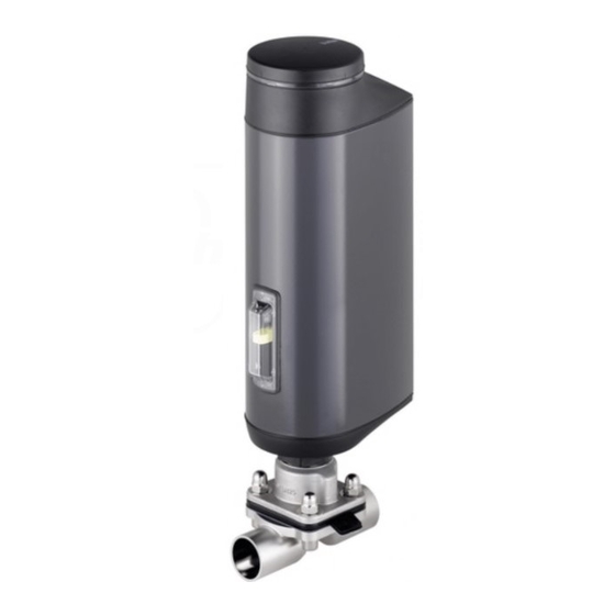
Contact addresses can be found on the final pages of the printed or cable gland) operating instructions. Actuator cover And also on the Internet at: www.burkert.com Actuator housing Warranty Transparent window Do not unscrew with position The warranty is only valid if the device is used as intended in accor- pressure compen- indicator dance with the specified application conditions. sation element! Information on the Internet FE functional Actuator base ground Operating instructions and data sheets for Types 3323, 3324 and Bore for monitoring 3325 can be found on the Internet at: www.buerkert.com. leaks Diaphragm Line connection Valve body Fig. 1: Structure, electromotive diaphragm valve Type 3323 English... -
Page 9: Display Of The Device Status
Type 3323, 3324, 3325 Technical data Display of the device status TECHNICAL DATA To indicate the device status and the valve position, different LED The following product-specific information is indicated modes can be set (description see main instructions). on the type label: LED mode set at the factory: “Valve mode w/ warnings”. • Voltage [V] (tolerance ±10 %) and current type 5.2.1 Displays in valve mode w/ warnings • Diaphragm material and material of the valve body When device status “Normal”: Permanently lit in the color of the • Fieldbus standard valve position. -
Page 10: Type Label
Type 3323, 3324, 3325 Technical data Type label 6.4.1 UL additional label (Example) Example: Type AE3323 Material valve body, line connection Da (ø outer) Power Supply Di (ø inner), flow capacity SELV / PELV only! Maximum permitted medium pressure, Diaphragm material, LISTED Diaphragm size Process Control Equipment voltage, direct current, max. power consumption E238179 Type, function, fieldbus standard Fig. 3: UL additional label (example) 3323 ON/OFF-control AS-Interface Labeling of the bodies... -
Page 11: Operating Conditions
Type 3323, 3324, 3325 Technical data WARNING Company logo Material Reduced sealing function if medium pressure too high. Heat 1.4435 316L(VP) XXXXXXXX As the diaphragm valve is closed against the medium flow, the Nominal PN16 / CWP150 medium pressure may become too high and prevent the valve pressure from closing tightly. ▶ The medium pressure must not be greater than the maxi- Connection mum value specified on the type label. orifice and pipe Danger due to escape of hot medium. - Page 12 Type 3323, 3324, 3325 Technical data 6.6.1 Permitted temperature ranges Permitted medium temperature for diaphragm materials: The permitted medium and ambient temperature ranges Diaphragm Temperature ranges Steam sterilisation depend on various factors: material • Medium temperature: depends on the material of the PTFE/EPDM (EA) -10...+130 °C +140 °C/60 min. valve body and diaphragm materials. EPDM (AD), • Ambient temperature: depends on the medium advanced PTFE/ -5...+143 °C +150 °C/60 min.
- Page 13 Type 3323, 3324, 3325 Technical data Permitted medium temperature for valve bodies made of plastic The permitted medium temperature for valve bodies made of plastic depends on the medium pressure. DN 15 - 40 PVDF 20 40 60 80 100 120 140 Temperature [°C] Fig. 6: Graph: Medium temperature and medium pressure for valve bodies made of plastic Medium temperature [°C]...
-
Page 14: General Technical Data
Type 3323, 3324, 3325 Technical data General technical data Electrical data Materials DANGER! A ctuator: PPS and aluminum powder-coated Electric shock. V alve body M etal: stainless steel board material Protection class III is only guaranteed when using a SELV (types 3324 and 3325), power supply unit or PELV power supply unit. - Page 15 Type 3323, 3324, 3325 Technical data PTFE for each diaphragm size EPDM for each diaphragm size Medium pressure in [bar] Medium pressure in [bar] Fig. 9: Energy consumption of actuator for each diaphragm size, PTFE Fig. 8: Energy consumption of actuator for each diaphragm size, EPDM...
-
Page 16: Installation Of The Valve
Type 3323, 3324, 3325 Installation of the valve INSTALLATION OF THE VALVE NOTE! WARNUNG Consider voltage drop in supply line. Example: with a cable cross-section of 0.34 mm a copper Risk of injury from improper assembly. cable may have a maximum length of 8 meters. ▶ The assembly may be carried out only by trained technicians and with the appropriate tools. Digital outputs (optional): ▶ Secure system against unintentional activation. Current limit 1 00 mA ▶ After installation, ensure that the process is restarted in a controlled manner. Observe sequence! Digital inputs: 1. Apply supply voltage. -
Page 17: Installation Position Of The Diaphragm Valves
Type 3323, 3324, 3325 Installation of the valve Installation position of the diaphragm 7.1.2 Installation position of T-body valves Installation position: For supply of a medium: For removal of a medium: The installation position of the diaphragm valve varies depending on the valve body. One of the bores in the diaphragm socket, for monitoring leakage, must be at the lowest point. 7.1.1 Installation position of 2-way body Installation position: any position, preferably with the actuator facing up. Ensuring self-drainage: Fig. 11: Installation position of Type 3324 →... -
Page 18: Installation Of Devices With Socket Connection, Flanged Connection, Clamp Connection And Bond Connection
Type 3323, 3324, 3325 Installation of the valve Installation of devices with socket → Connect the device electrically. The position of the connections can be aligned by rotating connection, flanged connection, the actuator through 360°. For a description see chapter “7.5 clamp connection and bond Rotating the actuator”. connection A description of the electrical connection can be found in NOTE! chapter “8 Electrical installation”. Damage to the diaphragm. 7.2.1 Following installation ▶ To prevent damage, the valve must be in MANUAL operating state during installation. → When the operating voltage has been applied, make the required basic settings and adjustments for the electromotive diaphragm Devices are delivered with the MANUAL operating state preset. - Page 19 Type 3323, 3324, 3325 Installation of the valve 7.3.2 Welding tank bottom body Delivery condition for devices with welded connection The devices are delivered in a disassembled state. Observe sequence: Operating state: MANUAL. 1. W eld the tank bottom body onto the base of the tank Position of the actuator: Valve open. before installing the tank. Welding onto a tank which has already been installed is Installation is divided into the following steps: possible but more difficult. 1. W eld in valve body in disassembled state.
- Page 20 Type 3323, 3324, 3325 Installation of the valve 1. Welding tank bottom body onto the tank: 7.3.3 Installing diaphragm and actuator ATTENTION! Depending on the size of the diaphragm, there are different fas- tening types for the diaphragm. Before welding, note the following: ▶ Use only welding material which is suitable for the tank...
- Page 21 Type 3323, 3324, 3325 Installation of the valve → Hand-tighten the diaphragm into the pressure piece. 7.3.4 Mounting actuator on the valve body and making the electrical connections → Loosen by half a rotation. NOTE! → Align diaphragm. The identification tab on the diaphragm must protrude out of Damage to the diaphragm. the valve body at right angles to the longitudinal axis of the ▶ To prevent damage, the device must be in MANUAL oper- pipeline (see”Fig. 14”). ating state during installation. The actuator must be in the Fastening the diaphragm by pressing it in: “Valve open” position.
- Page 22 Type 3323, 3324, 3325 Installation of the valve Running M.SERVICE using buttons in the device: WARNING The 2 buttons for running the M.SERVICE are located under the dummy cover. Risk of injury due to non-observance of the tightening torque. Devices with ATEX approval or IECEx approval. The devices are secured with a special cover. The Non-observance of the tightening torque is hazardous as the removal of the cover is described in the additional manual device may be damaged. for electromotive control valves with ATEX approval and ▶ Observe tightening torque. IECEx approval. → Tighten the nuts crosswise to 1/3 of the tightening torque. → Then tighten the nuts crosswise to 2/3 of the tightening torque.
-
Page 23: Following Installation
Type 3323, 3324, 3325 Installation of the valve Rotating the actuator Holding device To protect the valve actuator from damage due to forces NOTE! and vibrations, a holding device is recommended. This Damage to the diaphragm. is available as an accessory. See operating instructions on the homepage www.buerkert.com. ▶ To prevent damage to the diaphragm, the valve must be open when the actuator is rotated. The position of the connections can be aligned by rotating the Following installation actuator through 360°. → In the case of devices which are not installed, clamp the valve → Following installation, make the required basic settings and body in a holding device. -
Page 24: Holding Device
Type 3323, 3324, 3325 Electrical installation ELECTRICAL INSTALLATION The actuator cannot be rotated if devices are fitted with The electromotive valve is available with one of 2 different con- a holding device. nection variants: • With circular plug-in connector (multi-pole model) Holding device • Cable gland with connection terminals → Attach holding device to the hexagon of the actuator as Signal values shown in the diagram. Operating voltage: 24 V NOTE! Digital input for control signal: 0 ...5 V = log “0”;... - Page 25 Type 3323, 3324, 3325 Electrical installation 8.1.2 X1 – M12 circular plug, 8-pole Selection of the connection line: When selecting the length and cross-section of the indi- Pin Wire color* Assignment (from point of view of the vidual wires, consider the voltage drop with reference to device) the maximum supply current. 8.1.1 Description of the circular plug-in Input signals from the control center (e.g. PLC) connectors 0...5 V (log. 0)
-
Page 26: Electrical Installation With Cable Gland
Type 3323, 3324, 3325 Electrical installation Electrical installation with cable gland 8.1.3 X3 – M12 circular plug, 4-pole or 5-pole, operating voltage WARNING Wire color Risk of injury from improper installation. without büS with büS Assignment (from point of view ▶... - Page 27 Type 3323, 3324, 3325 Electrical installation 8.2.1 Access to the connection terminals Removing actuator cover: Removing LED and storage module: To access the terminals, open the device as described below. Fastening screws Devices with ATEX approval or IECEx approval. Actuator cover The devices are secured with a special cover. The removal of the cover is described in the additional manual Fastening for electromotive control valves with ATEX approval and screws IECEx approval. Metal housing of the LED and 1. Removing dummy cover: storage module → To release, rotate the dummy cover counter-clockwise by 90°...
- Page 28 Type 3323, 3324, 3325 Electrical installation 8.2.2 Connecting the cables Connection terminals → Push the cables through the cable gland. NOTE! Allow for connection to spring-type terminals. ▶ Minimum length of the wire end ferrule: 8 mm ▶ Maximum cross-section of the wire end ferrule: 1.5 mm (without collar), 0.75 mm (with collar). Cable glands → Strip at least 8 mm insulation from the wires and crimp on wire end ferrules. → Connect the wires. The terminal assignment can be found in the tables below. FE functional ground → Tighten the union nut of the cable gland (tightening torque approx. 1.5 Nm (1.1 lbf ft)). NOTE! Fig. 22: Connecting the cables Damage or malfunction due to ingress of dirt and moisture.
- Page 29 Type 3323, 3324, 3325 Electrical installation * Electrical installation of büS network: Terminal Assignment (from point of view of the device) Terminals 1, 2 and 3 (CAN interface) are for the con- nection of the büS network. Digital output 1 24 V / 0 V Terminal 1 is bridged internally with terminal 9, but is not designed for the operating voltage. Digital output 2 24 V / 0 V Digital output GND 8.2.5 Closing the device NOTE! Tab. 8: Terminal assignment – input signal from the control center (e.g.
-
Page 30: Start-Up
Type 3323, 3324, 3325 Start-up START-UP Dummy cover WARNING Risk of injury due to improper operation. Improper operation may result in injuries as well as damage to the device and the surrounding area. LED and storage module ▶ The operating personnel must know and have understood the contents of the operating instructions. ▶ Observe the safety instructions and intended use. ▶ Only adequately trained personnel may start up the equip- ment and the device. Actuator cover Basic settings Overview of basic factory settings: Basic factory settings Fig. 23: Closing the device →... -
Page 31: Adjusting The Position Control - Running M.q0.Tune
Type 3323, 3324, 3325 Start-up Adjusting the position control - WARNING running M.Q0.TUNE Danger due to uncontrolled process after running the M.Q0. When the M.Q0.TUNE function is running, the position control TUNE function. is adjusted to the physical stroke of the actuator used and the required sealing force is determined. In doing so, the sealing If the M.Q0.TUNE is running without medium pressure, the point must be manually approached.It is important that the valve actuator will be incorrectly adjusted. is not completely closed. Based on this position, the device uses This will cause an uncontrolled process due to a leaking an algorithm to calculate the optimum sealing force. actuator or damage to the diaphragm. ▶ Run M.Q0.TUNE under medium pressure only. Sealing point: Position at which the valve is almost sealed. -
Page 32: Setting Automatic Operating State
Type 3323, 3324, 3325 Start-up Possible messages Devices with ATEX approval or IECEx approval. when M.Q0.TUNE Description The devices are secured with a special cover. The removal is canceled of the cover is described in the additional manual for elec- There are device errors. There is an error which is preventing tromotive control valves with ATEX approval and IECEx M.Q0.TUNE from running. approval. Time limit exceeded. The M.Q0.TUNE could not be run Running the M.Q0.TUNE function: within the time limit due to an error. -
Page 33: Operation
Type 3323, 3324, 3325 Operation OPERATION 10.1.1 LED illuminated ring The transparent LED illuminated ring, which transmits the light of WARNING the LEDs outwards, is attached to the dummy cover. The device status is indicated by a lit, flashing or rapidly flashing Danger due to improper operation. LED illuminated ring in one color or in alternating colors. Improper operation may result in injuries as well as damage to the device and the area around it. A complete description of the device statuses, errors ▶ The operating personnel must know and have understood and warnings, which are displayed in LED mode, the contents of the operating instructions. can be found in the operating instructions on the ▶ Observe the safety instructions and intended use. homepage www.buerkert.com. ▶ Only adequately trained personnel may operate the equip- 10.1.2 Mechanical position indicator ment and the device. -
Page 34: Basic Functions
Type 3323, 3324, 3325 Basic functions BASIC FUNCTIONS 10.2.1 DIP switches Settings The basic functions are set via the DIP switch position. Switch 1: Activate or deactivate safety position. See DIP switches DIP switches Basic function chapter “11.2”, page 35. Switch 2: Select safety position between NO and NC. See Activate or deac- chapter “11.2”, page 35. tivate safety position Switch 3: Not used. Set safety position Switch 4: For switching between AUTOMATIC mode and and effective MANUAL mode. direction See chapter “11.1”, page 35. (NC and NO) Not used 10.2.2 OPEN button and CLOSE button... -
Page 35: Switching Operating State, Automatic - Manual
Type 3323, 3324, 3325 Basic functions 11.1 Switching operating state, 11.2 Setting safety position and effective AUTOMATIC – MANUAL direction Factory setting: MANUAL operating state. The effective direction and the safety position are set using DIP switches 1 and 2. The operating state is switched with DIP switch 4 which is located under the dummy cover. Set-point value DIP 1 Devices with ATEX approval or IECEx approval. DIP 2 (Safety The devices are secured with a special cover. The removal... -
Page 36: Manual Actuation Of The Valve
Type 3323, 3324, 3325 Manual actuation of the valve MANUAL ACTUATION OF THE VALVE The valve can be manually actuated in 2 ways: electrically or DIP switches mechanically. Electrical manual control should usually be used to open and close the valve manually. Mechanical manual control is used only to open and close the valve in the event of a power failure. Mechanical manual control may be Operating state Release dummy used in a de-energized state only. MANUAL: cover 12.1 Actuating valve electrically DIP 4 ... -
Page 37: 12.2 Actuating Valve Mechanically
Type 3323, 3324, 3325 Manual actuation of the valve 12.2 Actuating valve mechanically → To release, rotate the dummy cover counter-clockwise by 90° and remove from the actuator housing. When the supply voltage is not applied, e.g. during installation or in the event of a power failure, the valve can be opened or closed Devices with ATEX approval or IECEx approval. with the mechanical manual control. The devices are secured with a special cover. The removal NOTE! of the cover is described in the additional manual for elec- tromotive control valves with ATEX approval and IECEx Damage to the device or diaphragm by mechanical manual approval. -
Page 38: Fieldbus Gateway
Type 3323, 3324, 3325 Fieldbus gateway FIELDBUS GATEWAY 13.2 Electrical connection EtherNet/IP, PROFINET, Modbus TCP The fieldbus gateway is connected with a circular plug-in con- nector M12, 4-pole. Pin 1 Transmit + Pin 2 Receive + Pin 3 Transmit – Fieldbus Pin 4 Receive – Fieldbus con- gateway nection M12 Tab. 14: Electrical assignment (2 Port Ethernet NOTE! Switch)Switch) To ensure electromagnetic compatibility (EMC), a shielded Fig. 32: Fieldbus gateway Ethernet cable must be used. Ground the cable shield on both... -
Page 39: 13.3 Access To The Büs Service Interface
Type 3323, 3324, 3325 Maintenance, troubleshooting MAINTENANCE, 13.3 Access to the büS Service interface TROUBLESHOOTING The büS Service interface is located inside the fieldbus gateway. The following maintenance work is required for the diaphragm To gain access, open the cover by turning it anticlockwise. valve. • After the first steam sterilisation or when required → Retighten body screws crosswise. • After maximum 10 switching cycles → Check the diaphragm for wear and replace if required. Media with medium or high viscosity and abrasive media require correspondingly shorter inspection intervals. • Replacing the SAFEPOS energy pack. The device outputs a maintenance message as soon as the SAFEPOS energy pack is to be replaced. Message: The remaining life time of the energy storage is approx. 25 %! The energy storage must be changed soon. 14.1 Visual inspection Perform regular visual inspections according to the conditions of büS Service... -
Page 40: 14.2 Replacing The Diaphragm
Type 3323, 3324, 3325 Maintenance, troubleshooting 14.2 Replacing the diaphragm 14.2.2 Removing the diaphragm ATTENTION! WARNING! Damage to the diaphragm Risk of injury due to escape of medium and pressure release ▶ To prevent damage, the device must be in MANUAL operat- It is dangerous to remove a device which is under pressure ing state when installing and removing the diaphragm. due to the sudden release of pressure or discharge of medium. ▶ The actuator must be in the "Valve open" position. ▶ Before removal, switch off the pressure and vent the lines. -
Page 41: Cleaning
Type 3323, 3324, 3325 Accessories ACCESSORIES → Remove body screws. → Remove valve body. 16.1 Communications software → Detach or unscrew diaphragm (see “Tab. 15”). The PC software Bürkert-Communicator is designed for commu- Diaphragm with bayonet catch: → Loosen and remove dia- nication with Bürkert devices. phragm by turning it 90°. A detailed description for installing and operating the → Install new diaphragm. PC software can be found in the associated operating For description see chapter “7.3.3 Installing diaphragm and instructions. -
Page 42: Disassembly
Type 3323, 3324, 3325 Disassembly DISASSEMBLY DANGER Observe the national waste disposal regulations. Risk of injury from high pressure and discharge of medium. If the device is under pressure when removed, there is a risk of a sudden pressure release and discharge of medium. TRANSPORT AND STORAGE ▶ Before removing the device, switch off the pressure and vent NOTE! or drain the lines. Transport damage. CAUTION Inadequately protected devices may be damaged during transportation. Risk of injury due to a heavy device. • Protect the device against moisture and dirt in shock- A heavy device can fall down during transport or during instal- resistant packaging during transportation. lation and cause injuries. • Prevent the temperature from exceeding or dropping below the ▶... - Page 44 www.burkert.com...
Need help?
Do you have a question about the 3323 and is the answer not in the manual?
Questions and answers