Smartrise SRU Programming Instructions Manual
Hide thumbs
Also See for SRU:
- Programming manual (4 pages) ,
- Programming instructions manual (11 pages)
Table of Contents
Advertisement
Advertisement
Table of Contents

Related Manuals for Smartrise SRU

Summary of Contents for Smartrise SRU
- Page 2 Page intentionally left blank...
- Page 3 Programming Instructions for SRU Boards Document History Date Version Summary of Changes Modified By Status May 9, 2019 Initial Submittal May 9, 2019 ©2019 Smartrise Engineering, Inc. All Rights Reserved Page i...
- Page 4 Instructions for SRU Boards Programming Page intentionally left blank Page ii © 2019 Smartrise Engineering, Inc. All Rights Reserved May 9, 2019...
-
Page 5: Table Of Contents
Tips to Preserve Settings During Board Replacement ................. 5 USB Debug Adapter ............................. 6 Replace a Functioning MR SRU Board for a Newer Revision Without Losing Settings ......6 Replace a Non-Functioning MR SRU Without Losing Settings ..............9 Software Extraction to Laptop ........................13 Download Zip File .......................... - Page 6 Figure 7: Transferred Parameters ..........................7 Figure 8: Re-established Communication ........................8 Figure 9: Remove MR SRU ............................9 Figure 10: Replacing MR SRU with CT SRU ......................... 10 Figure 11: New CT SRU ..............................11 Figure 12: Thee good SRU’s ............................12 Figure 13: Zip File Location ............................
-
Page 7: Replacing And Programming A Sru Board
Programming Instructions for SRU Boards Replacing and Programming a SRU Board All Smartrise SRU boards are backwards compatible with prior revisions. For example, Revision 8 boards can replace all prior revision boards. The main issue a technician will face is whether or not the replacement board has the same IO as the existing board. The following is a list of considerations when replacing a Smartrise SRU board: Revision 8 boards can replace all previous board revisions (Revision 5-7). -
Page 8: Access Code
Some software versions require an access code when powering up an SRU board for the first time. The access code is “XFFFF” or “X0000”. When prompted, press and hold the UP arrow button on the SRU board until the display reads “XFFFF” or “X0000” and then press the enter key. -
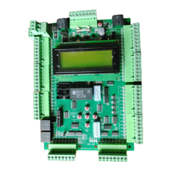
Page 9: Sru Board Revision Layouts
Programming Instructions for SRU Boards SRU Board Revision Layouts The figure below shows the Revision 5-7 SRU board. Figure 2: Revision 5-7 SRU Board May 9, 2019 ©2019 Smartrise Engineering, Inc. All Rights Reserved Page 3... -
Page 10: Figure 3: Revision 8 Sru Board
Instructions for SRU Boards Programming The figure below shows the Revision 8 SRU board. Figure 3: Revision 8 SRU Board Page 4 © 2019 Smartrise Engineering, Inc. All Rights Reserved May 9, 2019... -
Page 11: Tips To Preserve Settings During Board Replacement
Power down the controller. Remove the CAT5 pigtail that goes from the MR SRU NET port to the DIN rail. Using a standard CAT5 cable, connect the MR SRU to a new CT SRU board, NET port to NET port. -
Page 12: Usb Debug Adapter
• The software for the specific job is provided by Smartrise in two ways: • A Smartrise Flash drive is included in the job binder. • By an online software link. Contact Smartrise if you do not have the software for the particular jobsite. -
Page 13: Figure 6: Cat5 Cable Connection
Once the parameters are transferred, unplug the CAT5 cable and remove the original MR SRU board. Install the new CT SRU in place of the original MR SRU board and reprogram it as the MR SRU. Figure 7: Transferred Parameters May 9, 2019 ©2019 Smartrise Engineering, Inc. -
Page 14: Figure 8: Re-Established Communication
Instructions for SRU Boards Programming Reinstall the CAT5 pigtail from the DIN rail to the MR SRU NET. This re-establishes communication between the MR SRU to the original CT SRU. Figure 8: Re-established Communication Page 8 © 2019 Smartrise Engineering, Inc. All Rights Reserved... -
Page 15: Replace A Non-Functioning Mr Sru Without Losing Settings
Programming Instructions for SRU Boards Replace a Non-Functioning MR SRU Without Losing Settings Perform the following to replace a non-functioning MR SRU without losing settings. Remove the MR SRU. Figure 9: Remove MR SRU May 9, 2019 ©2019 Smartrise Engineering, Inc. All Rights Reserved Page 9... -
Page 16: Figure 10: Replacing Mr Sru With Ct Sru
Instructions for SRU Boards Programming Move the CT SRU to the machine room. Figure 10: Replacing MR SRU with CT SRU Reprogram the CT SRU as the MR SRU. Page 10 © 2019 Smartrise Engineering, Inc. All Rights Reserved May 9, 2019... -
Page 17: Figure 11: New Ct Sru
Programming Instructions for SRU Boards Install the new CT SRU. Figure 11: New CT SRU May 9, 2019 ©2019 Smartrise Engineering, Inc. All Rights Reserved Page 11... -
Page 18: Figure 12: Thee Good Sru's
Instructions for SRU Boards Programming Car is ready to run. Figure 12: Thee good SRU’s Page 12 © 2019 Smartrise Engineering, Inc. All Rights Reserved May 9, 2019... -
Page 19: Software Extraction To Laptop
The software can be provided by an online download link. If an update was made to the job OR the flash drive is not available, Smartrise can send an e-mail with a link to a downloadable zip file for the software. -
Page 20: Installing The Smartrise Programmer
Figure 17: Controller Software Folder Double click on the JCF file. If it does not open, then the Smartrise Programmer might not be correctly installed. See Installing the Smartrise Programmer Page 14 ©... -
Page 21: Figure 18: Jcf File
Figure 18: JCF File The Smartrise Programmer Interface Programmer displays. Figure 19: Smartrise Flash Programmer NOTE: All controller software is located on this interface except the group software. May 9, 2019 ©2019 Smartrise Engineering, Inc. All Rights Reserved Page 15... -
Page 22: Software Provided By Flash Drive
Programming Software Provided by Flash Drive Every Smartrise job is provided with a binder that consists of one flash drive containing software for the specific job. Smartrise controllers are shipped initially with the software already installed on the controller; these flash drives are provided as back-ups. -
Page 23: Installing The Sru Software
WARNING THE LAPTOP NEEDS TO BE FULLY CHARGED FOR THIS PROCESS. PLUGGING IN THE LAPTOP TO AN AC SOURCE WHILE INSTALLING THE SOFTWARE COULD DAMAGE THE SRU BOARD. DO NOT DISCONNECT THE PROGRAMMER POD FROM THE SRU BOARD WHILE THE CONTROLLER IS BEING PROGRAMMED. -
Page 24: Instructions For Programming A Ct/Cop Controller
Instructions for SRU Boards Programming Reprogramming an existing SRU board or programming a newly installed MR SRU board only? a. If reprogramming an existing SRU board, do not perform the DEFAULT ALL procedure as this will erase all existing settings. Go to step 10. -
Page 25: Instructions For Programming A Group Controller For Non-Simplex Jobs
The following procedure describes how to program a group controller for non-simplex jobs. Activate Dip Switch #1 on the group controller. (The group controller will not fault like the MR controller.) May 9, 2019 ©2019 Smartrise Engineering, Inc. All Rights Reserved Page 19... -
Page 26: Figure 24: J21 And J22 Checkbox Group Controller
Instructions for SRU Boards Programming Select the J21 checkbox on the Smartrise programming application. Figure 24: J21 and J22 Checkbox Group Controller Click the Begin Programming button on the bottom of the programming interface to begin programming the board. The progress report bar moves until the programming has been completed. Upon completion a Done message is displayed.
Need help?
Do you have a question about the SRU and is the answer not in the manual?
Questions and answers