
Subscribe to Our Youtube Channel
Related Manuals for mikroElektronika CLICKER 2


Summary of Contents for mikroElektronika CLICKER 2
- Page 1 dsPIC33 A compact starter kit with your favorite microcontroller and two mikroBUS sockets ™ dsPIC Page 1...
- Page 2 TO OUR VALUED CUSTOMERS I want to express my thanks to you for being interested in our products and for having confidence in MikroElektronika. The primary aim of our company is to design and produce high quality electronic products and to constantly improve the performance thereof in order to better suit your needs.
-
Page 3: Table Of Contents
2. dsPIC33EP512MU810 microcontroller 6. Oscillators 3. Programming the microcontroller 7. USB connection 3.1 Programming with mikroBootloader 8. Pinout step 1 – Connecting clicker 2 for dsPIC 8.1 mikroBUS pinout ™ step 2 – Browsing for .HEX file 9. click boards are plug and play! ™... -
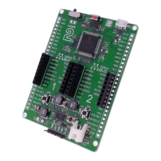
Page 4: Introduction To Clicker 2 For Dspic33
1x8 female headers with SPI, I 2C, UART, RST, PWM, Analog and Interrupt lines as well as 3.3V, 5V and GND power lines. clicker 2 for dsPIC33 board can be powered over a USB cable. Page 4... -
Page 5: Key Features
Key features ON/OFF switch 8 MHz crystal oscillator two 1x26 connection pads mikroBUS sockets 1 and 2 ™ Pushbuttons Additional LEDs LTC3586 USB power manager IC Power and Charge indication LEDs RESET button Micro USB connector dsPIC33EP512MU810 MCU Li-Polymer battery connector mikroProg programmer connector 32.768 KHz crystal oscillator Page 5... -
Page 6: Schematic
2.2µH 100k VCC-USB LDO3V3 VCC-USB RA10-VSENSE 88.7k VCC-USB 1µF 10pF 22µF 10000pF 2.2k 2.2k 100k R24 100 FERRITE USB-DET 0.1µF VCC-3.3V VCC-3.3V VBUS USB-D_N 16.9k 22µF 10µF USB-D_P AVCC USB-ID-RF3 VSYS USB MINIB clicker 2 for dsPIC33 schematic Page 6... -
Page 7: Power Supply
1. Power supply Battery power supply Figure 1-1: Connecting USB power supply You can also power the board using a Li-Polymer battery, via onboard battery connector. On-board battery charger circuit enables you to charge the battery over USB connection. LED diode (RED) will indicate when battery is charging. -
Page 8: Dspic33Ep512Mu810 Microcontroller
2. dsPIC33EP512MU810 microcontroller The clicker 2 for dsPIC33 development tool comes with the dsPIC33EP512MU810 device. This 16-bit low power high performance microcontroller is rich with on-chip peripherals and features 512 KB of program memory and 53,248 bytes of RAM. It has integrated full speed USB 2.0. support. -
Page 9: Programming The Microcontroller
3. Programming the microcontroller Figure 3-1: dsPIC33EP512MU810 microcontroller The microcontroller can be programmed in two ways: ∫ Using USB HID mikroBootloader, ∫ Using external mikroProg for dsPIC33 programmer Page 9... -
Page 10: Programming With Mikrobootloader
To start, connect the USB cable, or if already connected Firmware File folder press the Reset button on your clicker 2 for dsPIC33. Click the Connect button within 5s to enter the bootloader mode, clicker 2 for dsPIC dsPIC33EP512MU810 USB HID Bootloader v1.300.hex... -
Page 11: Step 2 - Browsing For .Hex File
step 2 – Browsing for .HEX file step 3 – Selecting .HEX file clicker2 for dsPIC33.hex HEX.file Figure 3-3: Browse for HEX Figure 3-4: Selecting HEX Click the Browse for HEX button and from a Select .HEX file using open dialog window. pop-up window (Figure 3.4) choose the .HEX file Click the Open button. -
Page 12: Step 4 - Uploading .Hex File
step 4 – Uploading .HEX file Begin uploading Figure 3-5: Begin uploading Figure 3-6: Progress bar To start .HEX file bootloading click the Progress bar enables you to monitor .HEX file uploading. Begin uploading button. Page 12... -
Page 13: Step 5 - Finish Upload
Figure 3-7: Restarting MCU Figure 3-8: mikroBootloader ready for next job Click OK button after the uploading process is finished. Press Reset button on clicker 2 for dsPIC33 board and wait for 5 seconds. Your program will run automatically. Page 13... -
Page 14: Programming With Mikroprog Programmer
You can also ICD2/3 program it programmer with ICD2® or ICD3® if clicker 2 for you reroute dsPIC33 1x5 programming the wires like Figure 3-9: mikroProg connector headers shown here. Page 14... -
Page 15: Mikroprog Suite For Pic ® Software
mikroProg Suite for dsPIC software ® dsPIC mikroProg programmer requires special programming software called mikroProg Suite for dsPIC . This ® software is used for programming of ALL Microchip microcontroller ® families, including PIC10 , PIC12 ® ® PIC16 , PIC18 , dsPIC30/33 , PIC24 ®... -
Page 16: Buttons And Leds
4. Buttons and LEDs The board also contains a reset button and a pair of buttons and LEDs, as well as an ON/OFF switch. The RESET button is used to manually reset the microcontroller— it generates a low voltage level microcontroller’s reset pin. -
Page 17: Power Management And Battery Charger
5. Power management and battery charger clicker 2 for dsPIC33 features LTC®3586-2, a highly integrated power management and battery charger IC that includes a current limited switching PowerPath manager. LTC®3586 also enables battery charging over a USB connection. Figure 5-1:... -
Page 18: Oscillators
6. Oscillators Board is equipped with 8MHz crystal oscillator (X1) circuit that provides external clock waveform microcontroller OSC1 and OSC2 pins. This base frequency is suitable for further clock multipliers and ideal for generation of necessary USB clock, which ensures Figure 6-1: proper operation of bootloader and your 8MHz crystal oscillator... -
Page 19: Usb Connection
7. USB connection dsPIC33 microcontrollers has an integrated USB module, which enables you to implement USB communication functionality to your clicker 2 board. Connection with target USB host is done over a micro USB connector which is positioned next to the battery connector. -
Page 20: Pinout
8. Pinout Reset pin VSYS System power supply Reference Ground Reference Ground RB15 RB14 RB13 Analog Lines RB11 PWM lines RB10 RD13 RD12 Interrupt Lines Digital I/O lines RA15 RA14 Digital I/O lines RG14 UART3 Lines RG12 SPI3 Lines C2 Lines RG13 3.3V power supply 3.3V power supply... -
Page 21: Mikrobus ™ Pinout
8.1 mikroBUS pinouts ™ Analog line PWM line Interrupt line Digital lines* UART1 lines RF12 SPI1 lines RD10 MISO C2 lines MOSI RF13 3.3V power supply 3.3V 5V power supply Reference ground Reference ground Analog line PWM line Interrupt line Digital lines* RD11 UART2 lines... -
Page 22: Click Boards ™ Are Plug And Play
9. click boards are plug and play! ™ Up to now, MikroElektronika has released more than 300 mikroBUS™ compatible click boards™. On the average, three click boards are released per week. It is our intention to provide you with as many add-on boards as possible, so you will be able to expand your development board with additional functionality. -
Page 23: Dimensions
10. Dimensions Page 23... - Page 24 No part of this manual, including product and software described herein, may be reproduced, stored in a retrieval system, translated or transmitted in any form or by any means, without the prior written permission of MikroElektronika. The manual PDF edition can be printed for private or local use, but not for distribution.
- Page 25 If you want to learn more about our products, please visit our web site at www.mikroe.com If you are experiencing some problems with any of our products or just need additional information, please place your ticket at www.mikroe.com/support If you have any questions, comments or business proposals, do not hesitate to contact us at office@mikroe.com Page 25...
Need help?
Do you have a question about the CLICKER 2 and is the answer not in the manual?
Questions and answers