
Related Manuals for mikroElektronika clicker STM32 M4


Summary of Contents for mikroElektronika clicker STM32 M4
- Page 1 A compact starter kit with your favorite microcontroller and a socket for click add-on ™ boards. New ideas are just a click away.
- Page 2 TO OUR VALUED CUSTOMERS I want to express my thanks to you for being interested in our products and for having confidence in MikroElektronika. The primary aim of our company is to design and produce high quality electronic products and to constantly improve the performance thereof in order to better suit your needs.
-
Page 3: Table Of Contents
Table of contents 1. What is STM32 M4 clicker? step 4 – Uploading .HEX file 2. Power supply step 5 – Finish upload 3. STM32F415RG microcontroller Programming with mikroProg programmer ™ Key microcontroller features mikroProg Suite for ARM software ™ ®... -
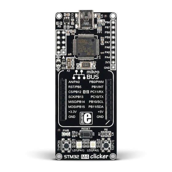
Page 4: What Is Stm32 M4 Clicker
1. What is STM32 M4 clicker? 64-pin STM32F415RG MCU Connection pads 16 MHz crystal oscillator mikroBUS socket ™ RESET button USB Mini-B connector 3.3V Voltage regulator JTAG Programmer connector 32.768 KHz crystal oscillator RTC battery pads Power indication LED Additional buttons Figure 1-1: STM32 M4 clicker Additional LEDs STM32 M4 clicker is an amazingly compact starter development kit which brings the innovative mikroBUS... - Page 5 3.3V VOLTAGE REGULATOR VCC-3.3 VCC-3.3 VCC-3.3 VCC-3.3 100nF 100nF 100nF 100nF 100nF 2.2uF 10uF VCC-3.3 VCC-5V 287K EN ADJ AP7331-ADJ VCC-3.3 VCC-5V FERRITE USB-DET VBUS USB-D_N 22pF USB-D_P VBAT 2.2uF 32.768KHz USB-ID PC13 VCAP2 TMS-SWD 22pF PC14 PA13 USB-D_P PC15 PA12 USB-D_N PA11...
-
Page 6: Power Supply
2. Power supply Figure 2-1: Connecting USB power supply through CN1 connector When the board is powered up the power indication LED will be automatically turned on. The USB connection can provide up to 500mA of current which is more than enough for the operation of all on-board and additional modules. Page 6... - Page 7 3.3V VOLTAGE REGULATOR VCC-3.3 VCC-5V VCC-3.3 FERRITE 10uF VCC-3.3 VCC-5V VBUS 287K EN ADJ AP7331-ADJ 100nF MINIB Figure 2-2: Power supply schematic Page 7...
-
Page 8: Stm32F415Rg Microcontroller
3. STM32F415RG microcontroller The STM32 M4 clicker development tool comes with the STM32F415RG microcontroller. This 32-bit high performance microcontroller is rich with on-chip peripherals and features 1024KB of Flash and 192KB of SRAM. It has integrated full speed USB 2.0. support. Key microcontroller features - Up to 168 MHz operation - 32-bit ARM®... -
Page 9: Programming The Microcontroller
4. Programming the microcontroller Figure 4-1: STM32F415RG microcontroller The microcontroller can be programmed in two ways: Using USB HID mikroBootloader, Using external mikroProg for STM32 programmer. ™ Page 9... -
Page 10: Programming With Mikrobootloader
Programming with mikroBootloader step 1 – Connecting STM32 M4 clicker You can program the microcontroller with a bootloader which is preprogrammed by default. To transfer .hex file from a PC to MCU you need bootloader software (mikroBootloader USB HID) which can be downloaded from: www.mikroe.com/downloads/get/2144/ mikrobootloader_usb_hid_STM32F415RG.zip After the mikroBootloader software is downloaded,... -
Page 11: Step 2 - Browsing For .Hex File
step 2 – Browsing for .HEX file step 3 – Selecting .HEX file Figure 4-3: Browse for HEX Figure 4-4: Selecting HEX Click the Browse for HEX button and from a Select .HEX file using open dialog window. pop-up window (Figure 3.4) choose the .HEX file Click the Open button. -
Page 12: Step 4 - Uploading .Hex File
step 4 – Uploading .HEX file Figure 4-5: Begin uploading Figure 4-6: Progress bar To start .HEX file bootloading click the Progress bar enables you to monitor .HEX file uploading. Begin uploading button. Page 12... -
Page 13: Step 5 - Finish Upload
step 5 – Finish upload Figure 4-7: Restarting MCU Figure 4-8: mikroBootloader ready for next job Click OK button after the uploading process is finished. Press Reset button on STM32 M4 clicker board and wait for 5 seconds. Your program will run automatically. Page 13... -
Page 14: Programming With Mikroprog ™ Programmer
Programming with mikroProg programmer ™ Figure 4-9: mikroProg connector ™ The microcontroller can be programmed with external mikroProg for STM32 programmer and mikroProg Suite for ARM software. ™ ™ ® The external programmer is connected to the development system via 2x5 JTAG connector soldered on the CN2 connector pads, Figure 4-9. -
Page 15: Mikroprog Suite For Arm Software
mikroProg Suite for ARM software ™ ® On-board mikroProg programmer requires special programming software called mikroProg Suite ™ ™ for ARM . This software is used for programming of all supported microcontroller families with ® Cortex -M3 and Cortex -M4 cores. The software has an intuitive interface and SingleClick ®... -
Page 16: Programming With St-Link V2 Programmer
Programming with ST-LINK V2 programmer In order to adjust the ST-LINK V2 programmer The microcontroller can also ™ to be connected to the development system, it be programmed with the ST-LINK V2 programmer is necessary to provide the appropriate adapter such as the mikroProg to ST-LINK V2 adapter. - Page 17 VCC-3.3 VCC-3.3 100nF 100nF 100nF 100nF 100nF 2.2uF 22pF VBAT 2.2uF PC13 VCAP2 32.768KHz TMS-SWD PC14 PA13 22pF PC15 PA12 PA11 PA10 #RST 22pF NRST STM32F415RG 16MHz 22pF VSSA NOTE Before attaching VDDA PB15 PB14 the programming PB13 connector, you PB12 VCC-3.3 have to solder the...
-
Page 18: Buttons And Leds
5. Buttons and LEDs Figure 5-1: Two buttons, two LEDs and a reset button The board also contains a reset button and a pair of buttons and LEDs. Each of these additional peripherals are located in the bottom area of the board. Reset button is used to manually reset the microcontroller. Pressing the reset button will generate a low voltage level on microcontroller’s reset pin. - Page 19 VCC-3.3 VCC-3.3 100nF 100nF 100nF 100nF 100nF 2.2uF 22pF 2.2uF VBAT 32.768KHz PA2/LED2 PC13 VCAP2 PC14 PA13 22pF PC15 PA12 PA11 PA1/LED1 PA10 #RST 22pF NRST PC0/T1 STM32F415RG 16MHz PC1/T2 22pF VSSA VCC-3.3 VCC-3.3 VCC-3.3 VDDA PB15 PA0/AN PB14 PA1/LED1 PB13 PA2/LED2 PB12...
-
Page 20: Rtc Battery
6. RTC battery STM32 M4 clicker features RTC battery pads for Figure 6-1: powering microntroller’s internal RTC module. Battery battery pads and jumper J1 is used as an alternative source of power, so the RTC module can keep track of time while primary source of power is OFF or unavailable. - Page 21 VCC-3.3 22pF 2.2uF VBAT 32.768KHz PC13 VCAP2 22pF PC14 PA13 PC15 PA12 PA11 PA10 22pF NRST STM32F415RG 16MHz 22pF VSSA VDDA PB15 PB14 PB13 PB12 VCC-3.3 100nF 100nF 100nF 100nF 100nF 2.2uF 2.2uF Figure 6-2: RTC battery schematic Page 21...
-
Page 22: Click Boards Are Plug And Play
7. click boards are plug and play! Up to now, MikroElektronika has released more than 90 mikroBUS compatible click Boards. On the ™ ™ average, one click board is released per week. It is our intention to provide you with as many add-on boards as possible, so you will be able to expand your development board with additional functionality. - Page 23 RFid click Relay click 8x8 click FM click Bluetooth2 click Thunder click USB SPI click ™ ™ ™ ™ ™ ™ ™ BarGraph click 7seg click THERMO click Gyro click EEPROM click LightHz click Pressure click ™ ™ ™ ™ ™...
-
Page 24: Dimensions
8. Dimensions 75.6 2979 71.6 2819 2.54 Legend mils Mounting hole size Ø Ø 17.2 25.4 1000 Page 24... - Page 25 No part of this manual, including product and software described herein, may be reproduced, stored in a retrieval system, translated or transmitted in any form or by any means, without the prior written permission of MikroElektronika. The manual PDF edition can be printed for private or local use, but not for distribution.
- Page 26 If you want to learn more about our products, please visit our web site at www.mikroe.com If you are experiencing some problems with any of our products or just need additional information, please place your ticket at www.mikroe.com/support If you have any questions, comments or business proposals, STM32 M4 clicker manual do not hesitate to contact us at office@mikroe.com...
- Page 27 Mouser Electronics Authorized Distributor Click to View Pricing, Inventory, Delivery & Lifecycle Information: Mikroe MIKROE-1675...
Need help?
Do you have a question about the clicker STM32 M4 and is the answer not in the manual?
Questions and answers