EBARA GS Instruction Manual
End suction volute pumps
Hide thumbs
Also See for GS:
- Instruction and maintenance manual (534 pages) ,
- Instruction manual (30 pages)
Table of Contents
Advertisement
Quick Links
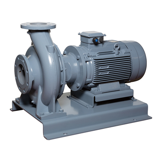
EBARA End Suction
Volute Pumps
GS/GSD Model
Instruction Manual
Thank you for choosing the EBARA GS/GSD Model End suction volute Pump. EBARA/Ebara Bombas
América do Sul Ltda.(EBAS) take every caution in manufacturing the product for safe use by the
customer. However, handling this pump in an inappropriate manner may reduce its functional capacity
and result in an accident.
This operation manual explains the proper procedures concerning the installation, operation, and
maintenance of the product. This manual should be read before conducting operation and
maintenance and inspections on this pump.
Installation personnel must provide copies of this manual to the customer's pump operation,
maintenance and inspection personnel. Keep this manual in a safe place where it can be consulted at
any time.
Be sure to issue the customer's pump operation, maintenance, and inspection personnel with copies of
this manual.
CONTENTS
Warnings .................................................. 2
1
Safety cautions ........................................ 2
2
Delivery checks........................................ 6
3
1. The pump and accessories..........................6
2. Nameplate ...................................................6
3. Lifting and carrying in/out.............................7
Specifications .......................................... 7
4
Installation ................................................ 8
5
1. Location .......................................................8
2. Pipes ...........................................................9
3. Alignment................................................... 10
4. Electrical connection .................................. 11
5. Electrical maintenance .............................. 12
Operation ................................................ 12
6
1. Preparation for operation ........................... 12
2. Operation・Stopping ................................. 13
CAUTION
To installation personnel:
Cautions for operation ..........................
5.
7
1. Daily inspection......................................... 16
2. Prolonged stoppage and storage............ 17
3. Replaceable parts ..................................... 17
Troubleshooting .................................... 19
8
Structure ................................................ 22
9
1. External view and residual risks ............... 22
2. Exploded view .......................................... 23
3. Accessories .............................................. 24
Disassembly and Assembly.................. 25
10
1. Disassembly ............................................. 25
2. Assembly .................................................. 31
- 1 -
.......................
..................
...............................................
14
14
15
15
Advertisement
Table of Contents

Related Manuals for EBARA GS


Summary of Contents for EBARA GS
-
Page 1: Table Of Contents
Instruction Manual CAUTION Thank you for choosing the EBARA GS/GSD Model End suction volute Pump. EBARA/Ebara Bombas América do Sul Ltda.(EBAS) take every caution in manufacturing the product for safe use by the customer. However, handling this pump in an inappropriate manner may reduce its functional capacity and result in an accident. -
Page 2: Warnings
1 Warnings Warnings in this manual provide information needed for safe operation of the pump, and instructions for preventing danger or injury to you or other people. So that you will know the degree and imminence of danger that warnings signify, they are divided into two grades, WARNING and CAUTION, according to the seriousness of what will happen if their instructions are not heeded. - Page 3 Install the pump in the locked pump room or equipment room. When it is placed outside, please arrange the fence and cover to avoid easy touch by the third person. If the rotating or high-temperature part is touched, unimaginable injury may happen.
- Page 4 When handling and installing the pump, give consideration to its mass and shape and be sure to work safely. There is a risk of the pump falling down and causing bodily injury. When handling chemicals, consult material safety data sheets (MSDSs) and other data to study the handling method, protective equipment to be used, precautions for disposal and so on, wear appropriate protective equipment and carry out work in a safe...
- Page 5 Make sure that the floor surface where the pump is installed has been waterproofed and treated for waste water. If it has not, severe damage could be caused should leakage occur. In facilities with living matter (fish farms, fish preserves, aquariums, etc.), always prepare a spare pump, as oxygen deprivation may result deaths due to pump failure.
-
Page 6: Delivery Checks
The product cannot be used for food processing or food transfer applications because it may cause development of bacteria and contamination by foreign matter. Ensure that all connection screws in electrically conductive parts are securely fastened. Otherwise, there is a risk of heat generation, malfunction and burnout. -
Page 7: Lifting And Carrying In/Out
Fig.2 Lifting and carrying in/out the pump (dashed line) or pump set (solid line) 4 Specifications GS/GSD pump is a hydraulic part of device that moves liquid by physical or mechanical action and is of end suction own bearings. GS pump complies with EN733 dimensions. -
Page 8: Installation
*1 Voltage fluctuation: Within ±10% of rated voltage. Frequency fluctuation: ±5% of rated frequency. Simultaneous fluctuation of voltage and frequency: Sum of both absolute values shall be 5% or less. Ambient temperature:0 to 40 ℃ (32 to 104 ℉) 、humidity:85% or less (no condensation), altitude: up to 1000m. -
Page 9: Pipes
2. Pipes The installation must be done according to the arrangement shown in the Figure: 1 Pump 2 Motor 3 Pipe Support 4 Flexible Joint 5 Check valve 6 Gate valve 7 Foot valve 8 Eccentric reduction 1~1.5D ≥2D 1~1.5D Fig.2 Installation view 1. -
Page 10: Alignment
- The suction pipe will be installed with an upward gradient towards the pump (of more than 1%) to avoid the formation of air bubbles. The pipes and other accessories must be connected in such a way so as not to create any air intake between the different elements. - Make sure that the suction pipe is as short and straight as possible and try to avoid any unnecessary curves or additional length. -
Page 11: Electrical Connection
4. Electrical connection Perform wiring work correctly as specified by electrical facility technical standards and extension codes. Incorrect wiring could result in electric shock and fires. Warning Install and ground an earth cable. Electric shock could occur during accidents or electric leakage. Make sure that any one of three terminals of the three-phase motor are not lose or disconnected. -
Page 12: Electrical Maintenance
5. Electrical maintenance Any work on the motor must be carried out with the appliance switched off and after disconnecting the mains power supply. - Check on a regular basis that the requirements regarding installation and electrical connections are complied with. - Comply with the lubrication schedule for the bearings and the type of grease (if it is specified on the motor nameplate). -
Page 13: Operation・Stopping
2. Operation・Stopping If there is a power failure, turn the power switch off. Warning Otherwise, the pump may start-up suddenly when the power supply is resumed, exposing personnel to danger. The correct direction of rotation is clockwise when looking from the motor Note side. -
Page 14: Adjustment Of Gland Packing
3. Adjustment of gland packing・・・For gland packing type For gland packing specification, make sure the water leakage is moderate according to Table 2. Prevent over tightening and uneven tightening gland packing from happening. If the water leakage could not be adjusted, there might be a deterioration occurring at shaft seal parts. -
Page 15: Cautions For Operation
5. Cautions for operation If the pump is operated for long periods with the discharge valve closed, the water temperature inside the pump will Warning rise, causing an accident. Do not operate the pump with the discharge valve closed for longer than 1 minute. (1) The frequent starting up and stopping of the pump will cause damages. -
Page 16: Daily Inspection
1. Daily inspection (1) If pressure, current, capacity, vibration, or noisy differ markedly from normal, trouble of some kind is probably going to occur, and you should take prompt corrective action. Refer to Troubleshooting for diagnosis and corrective action. You are advised to post a Daily Operation Condition Check Sheet. -
Page 17: Prolonged Stoppage And Storage
2. Prolonged stoppage and storage (1) If you have installed a spare pump, run it from time to time and keep it ready for operation anytime. (2) When the pump is out of use for three months or more, the gland packing unit might be rust-eaten. Please take the old gland packing unit out, remove moisture from the stuffing box, and install new gland packing unit into the stuffing box. - Page 18 Table 5 Model list for replaceable parts N om i nal D I A . / O -R i ng m m G rand N om i nal B eari ng M echani cal P acki ng D I A . N um ber Seal N om i nal I nner D I A .
-
Page 19: Troubleshooting
8 Troubleshooting Although the equipment usually functions according to the user's requirements, in some cases its operation may not come up to expectations due to problems with the system or the power supply. The following table may be useful in finding possible solutions in the event of failures or malfunctions: 1. - Page 20 Power surge - The voltage is low or the imbalance - Check the power supply. between the phases is high. - The head is too low, or the flow rate is - Partially shut off the delivery too high valve. - 50 Hz pump is being used at 60 Hz.
- Page 21 2. Motor Fault Causes Measures to be taken It does not work - The winding is broken or has been cut. - Repair in specialist workshop. - Stator short-circuited. - Repair in specialist workshop. - The bearings are blocked. - Repair the bearings. - The voltage is low.
-
Page 22: Structure
9 Structure 1. External view and residual risks ③ ⑧ ⑤ ② ④ ① ⑥ ⑦ Name Name Casing Name plate Driving shaft end (with key) Protector Discharge flange Drain plug Suction flange Air vent plug Fig.6 External view Table 6 Residual risks Operation Risk Measures to be taken... -
Page 23: Exploded View
2. Exploded view Model GS This figure shows a Model GS (GS200-500) for example. Depending on the model, your pump may vary slightly. Description Qty. Description Qty. Description Qty. Key form AB Gasket Casing Ring Shaft Shaft Sleev e Spring Pin... -
Page 24: Accessories
Cross-section drawings indicating the materials of the components can Note be obtained from EBAS sales offices or dealers. 3. Accessories Standard accessories (with motor) Common base (GS/GSD)………………………………………1 Coupling (GS) ············································ 1 set Coupling guard (GS) ··································· 1 set - 24 -... -
Page 25: Disassembly And Assembly
Make sure that all replacement parts are available before you start to assemble/disassemble the pump. ※ Make sure that all appropriate tools are available before you start to disassemble/assemble the pump. 1. Disassembly Model GS STEP.1 STEP.3 Drain all water from Casing (35). Remove the Stay (12) from the Bearing Casing (11). - Page 26 STEP.4 STEP.7 Remove the Casing Cover (27) from Casing Remove the Impeller (29) from the Shaft (2) (35). through the key. STEP.5 STEP.8 Remove the O-Ring (28) from the Casing Cover Remove the Key (3) of impeller side from the (27).
- Page 27 STEP.10 STEP.12 Remove the Casing Cover (27) from the Bearing Remove the Gland (21), the Gland Bolts (20) and Casing (11). the Nuts. Then remove the Gland Packings (22) and the Lantern Ring (23) from the Casing Cover (27). STEP.11 Remove the Gasket (17) and Shaft Sleeve (18) from Shaft (2).
- Page 28 STEP.15 STEP.18 Romove the Casing Cover (27) from the Bearing Remove the Bearing Cover (6) from the Bearing Casing (11). Casing (11). STEP.19 STEP.16 Remove the Shaft (2) from the Bearing Casing (11). Remove the Mechanical Seal from Casing Cover (27).
- Page 29 Remove Pump Bushing(4) from Motor Bushing(2). STEP.3 “1.Disassembly Refer Model GS(From STEP.4 to STEP.8 and STEP.14)” STEP.4 Remove Casing Cover(18) from Bracket(12). STEP.8 Remove Set Screw(7) from Nut(6) and Pump Bushing(4). STEP.5 Remove Mechanical Seal(19) from Casing Cover(18). - 29 -...
- Page 30 STEP.9 STEP.12 Remove Nut(6) from Shaft(5). Remove Stud Bolt(8) from Motor Bushing(2). STEP.10 STEP.13 Remove Pump Bushing(4) from Shaft(5). Remove Set Screw(3) from Motor Bushing(2). STEP.11 Remove Key(11) from Shaft(5). STEP.14 Heat the Motor Bushing (2) with a burner and pull out with a pulley removing tool.
-
Page 31: Assembly
2. Assembly Tighten torques for hexagon bolts and nuts; 1/4”: 4.5 Nm, 5/16”: 11 Nm, 3/8”: 22 Nm, 1/2”: 38 Nm, 5/8”: 93 Nm, 13/16”: 181 Nm, 15/16”: 313 Nm. Model GS STEP.1 STEP.3 Assemble the Casing Ring (33) and Spring Pin Assemble 2 Bearings (7) to the Shaft (2). - Page 32 STEP.6 STEP.8 Assemble Deflectors (4) to Bearing Cover (6) Insert the Gland Packings (22) and the Lantern and Bearing Casing (11). Ring (23) into the Casing Cover (27). Then assemble the Gland (21), the Gland Bolts (20) and the Nuts (19) by hand to fix the above-mentioned parts.
- Page 33 STEP.10 STEP.13 Assemble the Casing Cover (27) to the Bearing Assemble the Casing Cover (27) to the Bearing Casing (11). Casing (11). STEP.11 STEP.14 Tighten the Nuts (19). Assemble the Mechanical Seal to the Shaft (2). Proceed to STEP.15 next. Proceed to STEP.15 next.
- Page 34 STEP.16 STEP.19 Assemble the Impeller (29) to the Shaft (2) Assemble the Casing Cover (27) to Casing (35). through the key. STEP.17 STEP.20 Assemble the Washer (30) and the Hex Nut Assemble the Stay (12) to the Bearing Casing (31/32) for impeller to the Shaft (2). (11).
- Page 35 Model GSD STEP.1 Refer to “2.Assembly Model GS(STEP.1 and STEP.5 STEP.2)” Assemble key(11) to motor side of shaft(5). STEP.2 Heat the Motor Bushing (2) up to 100°C. Assemble the Motor Bushing (2) to motor shaft (1). STEP.6 Assemble pump bushing(4) to motor side of shaft(5).
- Page 36 STEP.8 STEP.11 Make drill hole (size:φ5.2mm x 8mm) and tap hole Assemble bracket(12) to motor(1). (size:1/4”UNC x 5mm) in pump bushing(4) aligning with hole of flange of nut(6) in order to assemble set screw(7). STEP.12 Insert fixing ring of mechanical seal (19) into casing cover(18).
- Page 37 STEP.14 Refer to “2.Assembly Model GS(From STEP.14 to STEP.19)” STEP.15 Assemble protector(15) to bracket(12). - 37 -...
- Page 38 If you have any enquiries, please feel free to contact us. Ebara Bombas América do Sul Ltda. Filial Vargem Grande do Sul - Fábrica Avenida Manoel Gomes Casaca, 840 Parque Industrial - PO Box 72 CEP 13880-000 - Vargem Grande do Sul – São Paulo - Brasil Telefone +55 (19) 3641-9100 - Fax +55 (19) 3641-5555 www.thebe.com.br...
Need help?
Do you have a question about the GS and is the answer not in the manual?
Questions and answers