Table of Contents
Advertisement
Quick Links
Advertisement
Table of Contents

Related Manuals for EBARA GS 80-250/A2


Summary of Contents for EBARA GS 80-250/A2
- Page 1 STANDARDISED END SUCTION PUMPS Instruction and maintenance manual...
- Page 2 Instruction and Maintenance Manual...
-
Page 3: Table Of Contents
Instruction and Maintenance Manual CONTENTS 1. INTRODUCTION..................... 4 2. SAFETY........................4 2.1 PREPARATION AND TRAINING OF STAFF 2.2 MAINTENANCE 3. TRANSPORT AND STORAGE................5 4. SPECIFICATIONS....................5 5. INSTALLATION....................... 7 5.1 INSTALLATION POINT 5.2 LIFTING 5.3 CEMENTED BASE 5.4 PIPES 5.5 ALIGNMENT 6. -
Page 4: Introduction
Instruction and Maintenance Manual 1. INTRODUCTION Thank you for choosing this EBARA GS model pump. This operating manual describes the correct installation, operation and maintenance procedures of the product. EBARA pays great attention to the manufacturing of its products so that their use by end-users may be as safe as possible. -
Page 5: Preparation And Training Of Staff
The responsibility, skills and supervision of the personnel fall within the remit of the employer. If the staff do not have the appropriate knowledge, they must be duly trained. If required, the employer may receive proper training directly from EBARA or from the distributor of this equipment. - Page 6 Instruction and Maintenance Manual The GS pump conforms to the dimensions required by EN 733. Its applications include climate control and building services, water supply, industry, etc. Other specifications are shown in the following table: Description Standard Temperature -10 to 120 ºC Density Liquid In accordance with...
- Page 7 Instruction and Maintenance Manual Overall Sound Pressure Level dB(A) 2 Pole 4 pole Model 2900 rpm 1450 rpm 32-125 32-160 32-200 32-250 Note: The overall 40-125 sound pressure level is the value measured 1m 40-160 away from the pump 40-200 unit, and does not 40-250 include driver noise.
-
Page 8: Installation
Instruction and Maintenance Manual 5. INSTALLATION 5.1 INSTALLATION POINT (1) Install the equipment in an easily-accessible place in order to carry out overhauls and maintenance. (2) Prohibit access to unauthorised persons by using related closure points. (3) Place the equipment as close as possible to the water supply, making sure that the difference in height between the water surface and the pump shaft is minimal and that the length of the suction pipe is as short as possible. -
Page 9: Pipes
Instruction and Maintenance Manual Generally, an incorrect cement base is the cause of premature failure and this invali- dates the warranty period. 5.4 PIPES The installation must be done according to the arrangement shown in the Figure: Pump Motor Mount Elastic sleeve Check valve Shut-off valve... - Page 10 1500 RPM 3000 RPM DN suct. x DN delivery DN pipe Reduction DN pipe Reduction...
-
Page 11: Alignment
Instruction and Maintenance Manual 5.5 ALIGNMENT The common base may be distorted when foundation bolts are tightened during intallation. Ensure correct alignment as indicated in table Dimensions [mm] Without spacer With spacer External diameter < 0.1 2.0 - 4.0 < 0.1 <... -
Page 12: Operation
Instruction and Maintenance Manual 6. OPERATION 6.1 BEFORE STARTING THE PUMP Make sure that the pipes are flushed after the installation is completed, since any impurities may lead to faults, noise and excess wear on the mechanical seal and other parts of the pump. Check that the pump turns easily by spinning the shaft with your hand. -
Page 13: Starting The Pump
Instruction and Maintenance Manual 6.2 STARTING THE PUMP 1. Shut off the main delivery valve. Open the suction valve if it is closed. 2. Turn on and off the switch to start the motor once or twice, to ensure that there are no faults in the start up. -
Page 14: Maintenance
. MAINTENANCE... -
Page 15: Daily Inspection
Instruction and Maintenance Manual 7.1 DAILY INSPECTION 1. Significant variations in pressure, capacity, electricity, vibrations or noise may be sign of a malfunction of the pump. Refer to the table “Failures and Measures to be taken”. It is advisable to keep a daily register on the operating conditions with a view to quickly discovering any symptoms that may be the result of a potential failure. -
Page 16: Precautions During Storage
Instruction and Maintenance Manual 7.3 PRECAUTIONS DURING STORAGE 1. The pump body may fracture if the water inside freezes; insulate the pump or remove all the water from the inside. 2. If you have any spare pumps, you must perform test runs on them on a regular basis and keep them ready for use at all times. - Page 17 Instruction and Maintenance Manual Shaft Casing Wear Ring unit O’ Ring Front Rear Model 32-125 230# 3.53x183.74 76 3.53x183.74 32-160 230# 3.53x234.54 32-200 230# 3.53x278.99 32-250 230# 3.53x183.74 40-125 230# 40-160 230# 3.53x183.74 40-200 230# 3.53x234.54 3.53x278.99 40-250 230# 3.53x355.19 40-315 240# 3.53x183.74...
-
Page 18: Troubleshooting
Instruction and Maintenance Manual 7.5 TROUBLESHOOTING Although the equipment usually functions according to the user's requirements, in some cases its operation may not come up to expectations due to problems with the system or the power supply. The following table may be useful in finding possible solutions in the event of failures or malfunctions: PUMP Fault... - Page 19 Instruction and Maintenance Manual The pump has no flow - The pump does not turn. - Check that the impeller is free. rate - Open the valve. - The delivery valve is closed or half-closed. - The suction head is too - Check the project.
- Page 20 Instruction and Maintenance Manual Power surge - The voltage is low or the - Check the power supply. imbalance between the phases is high. - 50 Hz pump is being used at - Check the nameplate 60 Hz. details. - Foreign bodies inside the - Remove foreign bodies.
- Page 21 Instruction and Maintenance Manual Excessive water - Defective fitting of the - Fit it correctly. mechanical seal. leakage from the shaft seal. - The mechanical seal is - Replace the mechanical damaged. seal. - Overpressure in - Review the project. delivery.
-
Page 22: Residual Risks
Instruction and Maintenance Manual - The bearings are blocked. - Repair the bearings. - Stator short-circuited. - Repair in specialist workshop. - Repair in specialist - Stator earthed. workshop. Low rotation speed. - Low voltage. - Change the nominal voltage. - Poor Star/Delta - Correct the cabling. -
Page 23: Construction
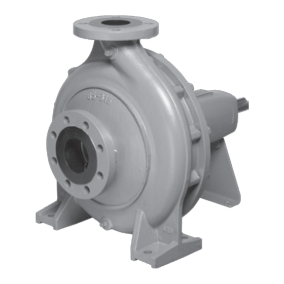
Instruction and Maintenance Manual 8. CONSTRUCTION This figure shows a standard GS model. There may be some variations depending on the model. Num. Name Num. Name Pump body High temperature label Shaft with key Shaft guard Delivery flange Drainage cap Suction flange Air relief cap Nameplate... -
Page 24: Dismantling And Fitting
Instruction and Maintenance Manual Parts list for a pump with mechanical seal Num. Name Quant. Num. Name Quant. Pump body Foot Protection 107-1 Clearance ring Seal disk 107-2 Clearance ring Impeller Mechanical seal Shaft Pump body O-ring 039-1 Key 120-1 Tensioner bolt 6/../16 039-2 Key 120-2 Nut and washer... -
Page 25: Fitting
10. REPAIR AND WARRANTY Order any repairs for the equipment directly from our company or from our approved technical support services. EBARA warrants free repairs according to the conditions listed below: 1. The equipment warranty period is one year from the date of purchase. - Page 26 EBARA, or in the event of repairs or modifications carried out by unauthorised personnel.
Need help?
Do you have a question about the GS 80-250/A2 and is the answer not in the manual?
Questions and answers