
Subscribe to Our Youtube Channel
Related Manuals for Meinberg IMS VSI180


Summary of Contents for Meinberg IMS VSI180
- Page 1 SETUP GUIDE IMS VSI180 Hot-Plug Module 22nd February 2021 Meinberg Funkuhren GmbH & Co. KG...
-
Page 3: Table Of Contents
Cabling ........... . . 4 Front Connectors IMS VSI180 Status LEDs . -
Page 4: Imprint
1 Imprint 1 Imprint Meinberg Funkuhren GmbH & Co. KG Lange Wand 9, 31812 Bad Pyrmont / Germany Phone: + 49 (0) 52 81 / 93 09 - 0 Fax: + 49 (0) 52 81 / 93 09 - 230 Internet: https://www.meinbergglobal.com... -
Page 5: Introduction
The receiver module then serves the HPS100 module with an accurate and stable time base. The LTOS7 manual provides a complete description of all configurations and status monitoring options of your Meinberg product. Download LTOS7 firmware manual: https://www.meinbergglobal.com/download/docs/manuals/english/ltos_7-00.pdf Compatibility The IMS-VSI180 is compatible with all LANTIME systems of the IMS family. -
Page 6: Important Safety Hints
Before any maintenance work on the system: • Backup of stored configurations is recommended (e.g. via USB stick or Web UI) • Please note the chapter "Prevention of ESD damage". • Please note the chapter "Supply voltage". IMS VSI180 Date: 22nd February 2021... -
Page 7: Additional Safety Hints
Keep all documents provided with the device for later reference. This manual is exclusively for qualified electricians or by a qualified electrician trained personnel who are familiar with the applicable national standards and specifications, in particular for the construction of high voltage devices. Date: 22nd February 2021 IMS VSI180... -
Page 8: Prevention Of Esd Damage
ESD protective covers, which are extremely wrinkled or even have holes, no longer protect against electrostatic discharge. ESD protective covers must not be low-resistance and metallically conductive if a lithium battery is installed on the assembly. IMS VSI180 Date: 22nd February 2021... -
Page 9: Supply Voltage
Never open a power supply unit cause dangerous voltages can even exist after it has been disconnected from the electrical supply. If a power supply is not working anymore, e.g. due to a defect, please send it back to Meinberg for necessary repairs. Non-observance of these safety instructions can cause serious personal injury and material damage. Installation, initial start-up and operation of the IMS System may only be performed by qualified technical experts. -
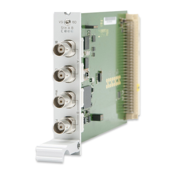
Page 10: Front Connectors Ims Vsi180
4 Front Connectors IMS VSI180 4 Front Connectors IMS VSI180 IMS VSI180 Date: 22nd February 2021... -
Page 11: Status Leds
Off No signal is present at the inputs Only a Word Clk In signal is present. Flashing Green Flashing yellow Only a PPS is present. Word Clk In and PPS are present. Green on Date: 22nd February 2021 IMS VSI180... -
Page 12: Blackburst Input
4 Front Connectors IMS VSI180 4.2 Blackburst Input Input Signal Black Burst (PAL) Input with VITC Reader Input with Prescaler mode (Frequency only) Signal level: 300 mV into 75 ohms (unbalanced) Time Code Formats: PAL SMPTE259M / ITU-R BT.470-6 SMPTE12M-1 / SMPTE ST309M... -
Page 13: Pulse Per Second Input
4.5 Pulse Per Second Input Input signal PPS (pulse per second) Signal level: Pulse lenght: 5 s, active high Connection type: BNC, female Cable: shielded coax line Date: 22nd February 2021 IMS VSI180... -
Page 14: Before You Start
Check the system for shipping damage. If the system is damaged or cannot be put into operation, contact Meinberg immediately. Only the recipient (the person or company receiving the system) can assert a claim against freight forwarder for shipping damage. -
Page 15: System Installation
CPU is disconnected. Also the management and monitoring functions are no longer available. RSC/SPT: "hot plugable" The switching function or the distribution of generated signals is interrupted while the RSC/SPT is disconnected. Date: 22nd February 2021 IMS VSI180... -
Page 16: Installation Of Hot-Pluggable Ims Modules
Make sure that the module is securely locked into the connector block before you fasten the two screws. Now you can put the installed module into operation. Attachment points of an 1U IMS system IMS VSI180 Date: 22nd February 2021... -
Page 17: Connecting The System
VSI180 - Audio- Video-Referenzeingang / Black Burst, LTC or Word Clock with VSG181 - audio and video signal reference input Figure: M1000 with HPS in master mode - synchronized by audio/video signal generator Date: 22nd February 2021 IMS VSI180... -
Page 18: Configuration Of Vsi180 Via Webinterface
Menü "IO Config Input Configuration VSI-Karte" Video Sync Interface: configurable Inputs Input 1: Video Sync In Format: PAL 625i Epoch: Signal Source: Single-ended signal input Time Code Modes: VITC Time Code Line: 6 - 22 IMS VSI180 Date: 22nd February 2021... - Page 19 Input 2: LTC In Type: LTC 25 FPS (Frames per Second) Input 3: Word Clk In Frequency: 1 kHz - 10 MHz Max Slip: 0.5 - 3.0 oscillations Date: 22nd February 2021 IMS VSI180...
-
Page 20: Status Monitoring Of The Ims-Vsi
The submenu "Status" of the "IO Config" allows you to view the status of each port of the installed IMS-VSI module. In addition, the current operating temperature of the module is displayed in this menu. IMS VSI180 Date: 22nd February 2021... -
Page 21: Rohs And Weee
Any transportation expenses for return- ing this product (at its end of life) have to be incurred by the end user, whereas Meinberg will bear the costs for the waste disposal itself. Date: 22nd February 2021...
Need help?
Do you have a question about the IMS VSI180 and is the answer not in the manual?
Questions and answers