
Subscribe to Our Youtube Channel
Related Manuals for Meinberg IMS-GNS181-UC


Summary of Contents for Meinberg IMS-GNS181-UC
- Page 1 MANUAL IMS-GNS181-UC Setup Guide Hot-Plug Module 31st January 2020 Meinberg Funkuhren GmbH & Co. KG...
-
Page 3: Table Of Contents
......4 Meinberg GNS-UC Receiver (GPS and Galileo) Technical Specifications GNS-UC Clock . - Page 4 1 Imprint 1 Imprint Meinberg Funkuhren GmbH & Co. KG Lange Wand 9, 31812 Bad Pyrmont / Germany Phone: + 49 (0) 52 81 / 93 09 - 0 Fax: + 49 (0) 52 81 / 93 09 - 230 Internet: https://www.meinbergglobal.com...
-
Page 5: Safety Instructions For Hot Pluggable Modules
• Place the module out of the box or after removal from the system with the component side to the top on a grounded and static-free surface. • Storage of an IMS module must be done in a dry place. • Installation or removal from hot-swap components only by authorized personnel! Date: 31st January 2020 IMS-GNS181-UC Setup Guide... -
Page 6: Additional Safety Hints
To ensure safe operation supply mains connected to this decice must be equipped with a fuse and a fault- current circuit breaker according to the applicable national standards for safe operation. The device must be connected to a protective earth with low grounding resistance according to the applicable national rules. IMS-GNS181-UC Setup Guide Date: 31st January 2020... -
Page 7: Cabling
Wiring or any other work done the connectors particularly when connectors are opened may never be carried out when the installation is energized. All connectors must be covered to prevent from accidental contact to life parts. ALWAYS ENSURE A PROPER INSTALLATION! Date: 31st January 2020 IMS-GNS181-UC Setup Guide... -
Page 8: Replacement Or Installation Of A Hot-Pluggable Ims Module
Make sure that the module is securely locked into the connector block before you fasten the two screws. Now you can put the installed module into operation. Attachment points of an 1U IMS system IMS-GNS181-UC Setup Guide Date: 31st January 2020... -
Page 9: Important Hints For Hot-Pluggable Ims Modules
"System". not "hot swappable" The central management unit must be disconnected from mains before replacement. RSC/SPT not "hot swappable" The RSC switching card must be disconnected from the mains before the replacement. Date: 31st January 2020 IMS-GNS181-UC Setup Guide... -
Page 10: Meinberg Gns-Uc Receiver (Gps And Galileo)
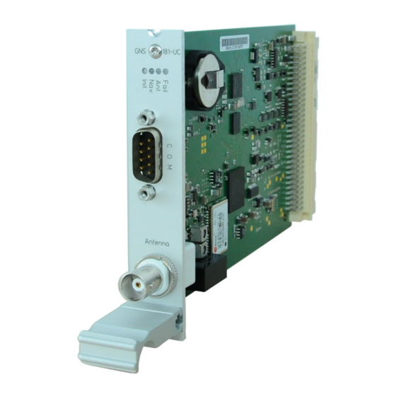
IMS-GNS181-UC - GPS/Galileo based Time Synchronization for Stationary and Mobile Applications using Meinberg Antenna/Converter Technology The IMS-GNS181-UC unit has a special receiver concept which is able to capture GPS and Galileo sig- nals using a standard Meinberg antenna/converter unit. The configuration supports to select one of these to be used exclusively or the combination of the sources. -
Page 11: Technical Specifications Gns-Uc Clock
Nav. green: positioning successfully red: antenna faulty or not connected yellow: the clock is synchronized by an external Signal - MRS mode (PPS, IRIG ...) Fail red: time has not synchronized Date: 31st January 2020 IMS-GNS181-UC Setup Guide... - Page 12 4 Meinberg GNS-UC Receiver (GPS and Galileo) Pin Assignment of the DSUB9 Connectors (male): Pin 2: RxD Pin 3: TxD Pin 5: GND Option "multiref" Reference signal via 9-pin DSUB connector (PPS + String Mode) Pin 1: PPS Pin 2: String *...
-
Page 13: Configuration Of Ims Modules Via Web Interface
Misc" - selection of the satellite navigation system A detailed overview of all other settings can be found in the current LANTIME firmware manual: "Web In- terface Documentation & Support" or on our manual download page: https://www.meinbergglobal.com/english/docs/ Date: 31st January 2020 IMS-GNS181-UC Setup Guide... -
Page 14: Meinberg Gps Antenna/Converter
4.1.2 Meinberg GPS Antenna/Converter 4.1.2.1 Introduction The Meinberg GPS antenna/converter unit combines a standard GPS patch antenna with a frequency converter which translates the original 1.5 GHz signal received from the GPS satellites to an intermediate frequency, so a standard coaxial cable type like RG58 can be used for antenna cable lengths up to 300 meters (1000 ft). If a low-loss cable type like RG213 is used then even 700 meters (2300 ft) between receiver and antenna are possible without requirement for an additional amplifier. - Page 15 The total length of an antenna cable from the antenna to each receiver must not exceed the specified maximum length according to the cable type. The position of the splitter in the antenna line does not matter. Date: 31st January 2020 IMS-GNS181-UC Setup Guide...
- Page 16 4 Meinberg GNS-UC Receiver (GPS and Galileo) Note: If the antenna cable is assembled locally instead of using a cable shipped with the GPS receiver it has to be made sure that the connectors have been soldered and assembled properly, and that there is no short-circuit in the cable or in one of the connectors.
-
Page 17: Powering Up A Gnss Receiver
GPS Satellites") as well as via the Web GUI ("Clock Receiver Information") you can check the number of satellites that are in view (i.e. above the horizon) and considered good (i.e. are healthy and can be tracked). Date: 31st January 2020 IMS-GNS181-UC Setup Guide...
Need help?
Do you have a question about the IMS-GNS181-UC and is the answer not in the manual?
Questions and answers