
Subscribe to Our Youtube Channel
Related Manuals for Meinberg IMS-FDM


Summary of Contents for Meinberg IMS-FDM
- Page 1 MANUAL IMS-FDM Setup Guide Hot-Plug Module 4th November 2020 Meinberg Funkuhren GmbH & Co. KG...
-
Page 3: Table Of Contents
..........Date: 4th November 2020 IMS-FDM Setup Guide... -
Page 4: Imprint
1 Imprint 1 Imprint Meinberg Funkuhren GmbH & Co. KG Lange Wand 9, 31812 Bad Pyrmont / Germany Phone: + 49 (0) 52 81 / 93 09 - 0 Fax: + 49 (0) 52 81 / 93 09 - 230 Internet: https://www.meinbergglobal.com... -
Page 5: Important Safety Hints
Before any maintenance work on the system: • Backup of stored configurations is recommended (e.g. via USB stick or Web UI) • Please note the chapter "Prevention of ESD damage". • Please note the chapter "Supply voltage". Date: 4th November 2020 IMS-FDM Setup Guide... -
Page 6: Additional Safety Hints
This manual is exclusively for qualified electricians or by a qualified electrician trained personnel who are familiar with the applicable national standards and specifications, in particular for the construction of high voltage devices. IMS-FDM Setup Guide Date: 4th November 2020... -
Page 7: Prevention Of Esd Damage
ESD protective covers, which are extremely wrinkled or even have holes, no longer protect against electrostatic discharge. ESD protective covers must not be low-resistance and metallically conductive if a lithium battery is installed on the assembly. Date: 4th November 2020 IMS-FDM Setup Guide... -
Page 8: Supply Voltage
Never open a power supply unit cause dangerous voltages can even exist after it has been disconnected from the electrical supply. If a power supply is not working anymore, e.g. due to a defect, please send it back to Meinberg for necessary repairs. Non-observance of these safety instructions can cause serious personal injury and material damage. Installation, initial start-up and operation of the IMS System may only be performed by qualified technical experts. -
Page 9: Replacement Or Installation Of A Hot-Pluggable Ims Module
Make sure that the module is securely locked into the connector block before you fasten the two screws. Now you can put the installed module into operation. Attachment points of an 1U IMS system Date: 4th November 2020 IMS-FDM Setup Guide... -
Page 10: Important Hints For Hot-Pluggable Ims Modules
CPU is disconnected. Also the management and monitoring functions are no longer available. RSC/SPT: "hot swappable" The switching function or the distribution of generated signals is interrupted while the RSC/SPT is disconnected. IMS-FDM Setup Guide Date: 4th November 2020... -
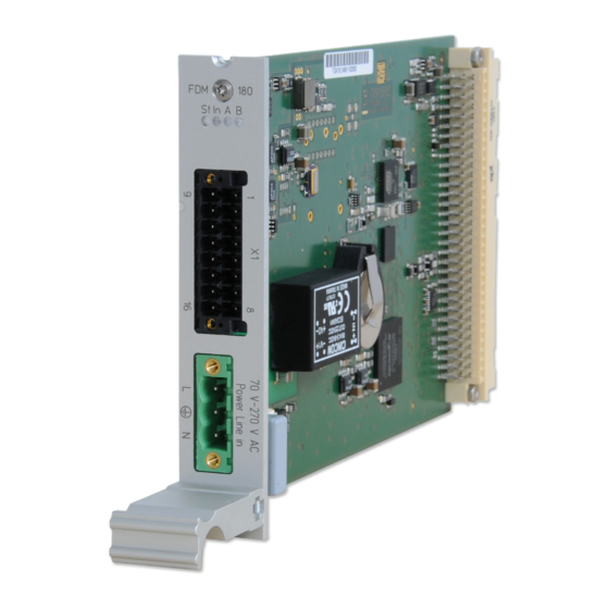
Page 11: Fdm - Frequency Deviation Monitoring
Timesync green Accurate ( 200 ns to reference) LED A: green FD (Frequency Deviation) within the configured limits FD Overflow LED B: green TD (Time Deviation) within the configured limits TD Overflow Date: 4th November 2020 IMS-FDM Setup Guide... - Page 12 -2.5 V ... +2.5 V, resolution: 16 Bit Electrical connectors: 96-pin VG-rail DIN 41612 Power supply: +5 V DC Current consumption: 0.4 A - 1 A Ambient temperature: 0 ... 50 C / 32 ... 122 F Humidity: Max. 85% IMS-FDM Setup Guide Date: 4th November 2020...
-
Page 13: Fdm Configuration Via Web Interface
Power Line Time: PLT - the time of the monitored power line Line Frequency: mains frequency (50Hz or 60Hz) Flags: transmitted Flags by FDM (Error Bits) Receiver State The "Receiver" tab displays all connected and configured receivers. Date: 4th November 2020 IMS-FDM Setup Guide... -
Page 14: Fdm Configuration
Max Positive Time Deviation: an error occurs if the frequency reaches the max positive constraint Timezone: used local timezone for reference time and powerline time Activate Logging: activate logging for FDM in XtraStats Reset FDM to restart the device IMS-FDM Setup Guide Date: 4th November 2020... - Page 15 The standard FDM telegram format contains the following values: mains frequency (FF.xxx Hz) frequency deviation (+-FF.xxx Hz) reference time (HH:MM:SS) power line time (HH:MM:SS.mmm) time deviation (+-MM:SS.mmm) Mode per second, per minute and on request Date: 4th November 2020 IMS-FDM Setup Guide...
- Page 16 Example: min: 45Hz and max: 55Hz @ 50Hz line frequency if the frequency deviation reach 45Hz the analog output is at -2.5 V and if 55Hz then at +2.5V with a resolution of 16bit DAC IMS-FDM Setup Guide Date: 4th November 2020...
- Page 17 0 for reset (example: if you already had one FDM an get another one and want that both FDM have the same time deviation value). Date: 4th November 2020 IMS-FDM Setup Guide...
- Page 18 Custom: Customized FDM time telegram, which consists of prefix, string and suffix Sent once per second Address: Address or host name of the message recipient (display or computer) Port: Used TCP/UDP port for telegram transmission Transport Protocol: Used protocol for telegram transmission (TCP/UDP) IMS-FDM Setup Guide Date: 4th November 2020...
- Page 19 Suffix of customized strings, control characters can be specified by their hex value (ASCII), for example: "\x0A" for LF (Line Feed) or "\x0D" for CR (Carriage Return) Append Timestamps: Indicates, whether a timestamp shall be appended to the message Date: 4th November 2020 IMS-FDM Setup Guide...
-
Page 20: Fdm Information
4 FDM - Frequency Deviation Monitoring 4.1.3 FDM Information IMS-FDM Setup Guide Date: 4th November 2020... -
Page 21: Serial Fdm Telegrams
The meaning of the several values is described below: FD:-00.016 The frequency deviation between calculated and nominal frequency, with sign character (+/-), resolution: 1mHz TD:+00.378 The time deviation between REF time and PL time„ with sign character (+/-), resolution: 1ms Date: 4th November 2020 IMS-FDM Setup Guide... - Page 22 The power line time, based on the mains frequency, (hours_minutes_seconds.milliseconds) Time jumps, like changeover in daylight saving or leap seconds, will not be executed by the PL time! 068_15_03_30 The reference time from the preconnected clock, (day-of-the-year_hours_minutes_seconds) IMS-FDM Setup Guide Date: 4th November 2020...
- Page 23 The time deviation between REF time and PL time, with sign character (+/-), resolution: 1ms, maximum: +-99.999s (the first digit is always 0!) F:49.984 The measured power line frequency with a resolution of 1mHz Date: 4th November 2020 IMS-FDM Setup Guide...
- Page 24 To correct the time deviation TD, please use the specified format. If the time deviation TD is accepted, the FDM confirms the command and applies the value within the next 2 seconds. Example of setting TD to 6.780 seconds: to FDM F27 B3 PS +6.780<CR><LF> from FDM F27 <CR><LF> IMS-FDM Setup Guide Date: 4th November 2020...
- Page 25 The frequency deviation between calculated and nominal frequency, with sign character (+/-), resolution: 1mHz SF+60.095 The measured power line frequency with a resolution of 1mHz ST12:17:53.463 The power line time, based on the mains frequency, (hours:minutes:seconds.milliseconds) Date: 4th November 2020 IMS-FDM Setup Guide...
-
Page 26: Error-Bits
No Power Line Time Init, the power line time has not (yet) been initialized The error bits can be read out serially on request by an "E" (ASCII code 45h) via the interfaces COM 0/1. The format of the response string is: ERROR:X8X7X6X5X4X3X2X1<CR><LF> IMS-FDM Setup Guide Date: 4th November 2020...
Need help?
Do you have a question about the IMS-FDM and is the answer not in the manual?
Questions and answers