
Related Manuals for Meinberg IMS-TCR180


Summary of Contents for Meinberg IMS-TCR180
- Page 1 SETUP GUIDE IMS-TCR180 Hot-Plug Module December 17, 2021 Meinberg Funkuhren GmbH & Co. KG...
-
Page 3: Table Of Contents
IMS-TCR180 - Status LEDs ........ -
Page 4: Imprint
1 Imprint 1 Imprint Meinberg Funkuhren GmbH & Co. KG Lange Wand 9, 31812 Bad Pyrmont, Germany Phone: + 49 (0) 52 81 / 93 09 - 0 Fax: + 49 (0) 52 81 / 93 09 - 230 Website: https://www.meinbergglobal.com... -
Page 5: Change Log
2 Change Log Version Date Revision Notes 06/03/2021 Initial version 1.01 12/17/2021 Addition of change log & troubleshooting chapter, minor corrections Date: December 17, 2021 IMS-TCR180... -
Page 6: Introduction
3 Introduction 3 Introduction This Setup Guide is a systematically structured guideline to assist you with the initial set-up of your Meinberg product. The IMS-TCR180 receiver module is used to decode and generate modulated (AM) and unmodulated (DC level-shift) IRIG-A / B / G, AFNOR, C37.118, and IEEE1344-formatted time codes. Time codes are transmitted by modulating the amplitude of a sinusoidal carrier wave, while unmodulated codes are transferred by modu- lating the pulse width of a TTL signal. - Page 7 Compatibility The IMS-TCR180 is an IMS module that is compatible with the following systems in the IMS product family and can be used in the following slots. System Compatibility - IMS TCR180 M500 M1000 M1000 S M2000 S M3000 M3000 S...
-
Page 8: Important Safety Information
Please ensure that IMS modules designed for "hot-plugging" (modules that are removable and insertable while a system is in operation) are always handled with the utmost care. Before performing any maintenance work on the system, Meinberg recommends: • backing up stored configurations (e.g., via USB flash drive or Web UI) •... -
Page 9: Prevention Of Esd Damage
ESD-proof bags that are crumpled or have holes cannot provide effective protection against electrostatic discharges. ESD-proof bags must have a sufficient electrical resistance and must not be made of conductive metals if the device has a lithium battery fitted on it. Date: December 17, 2021 IMS-TCR180... -
Page 10: Power Supply
In the event that a power supply unit is no longer working (e.g. defective), please return it to Meinberg for repair. Failure to observe these safety instructions may result in serious injury and/or property damage. The IMS system must only be installed, set up, and operated by qualified personnel. -
Page 11: Cabling
The battery is used to power components such as the RAM and the reserve real-time backup clock for the reference clock. If the battery voltage drops below 3 V DC, Meinberg recommends having the battery replaced. If the battery voltage drops below the specified minimum, the following behavior may be observed in the reference clock: •... -
Page 12: Module Connectors And Indicators Ims-Tcr180
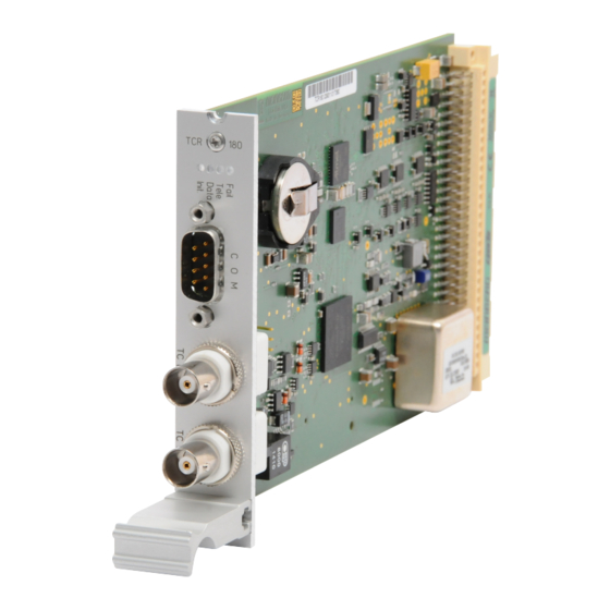
5 Module Connectors and Indicators IMS-TCR180 5 Module Connectors and Indicators IMS-TCR180 The numbering in the drawing above relates to the relevant subsection in this chapter. IMS-TCR180 Date: December 17, 2021... -
Page 13: Ims-Tcr180 - Status Leds
5.1 IMS-TCR180 - Status LEDs The LEDs indicate the following status conditions:. "Init" LED: Blue: Initialization phase of TCR180 Off: Oscillator not warmed up Green: Oscillator warmed up "Data" LED: Shows status after initialization Green: IRIG receiver has received a valid code at the input... -
Page 14: Comx Timestring - Rs-232
5 Module Connectors and Indicators IMS-TCR180 5.2 COMx Timestring - RS-232 Data Transfer Method: Serial Baud Rate/Framing: 19200 / 8N1 (Default) Time String Format: Meinberg Standard (Default) Pin Layout: Pin 2: RxD (receive) Pin 3: TxD (transmit) Pin 5: GND (ground) -
Page 15: Dcls Time Code (Unmodulated) Input
5.4 AM Time Code (Modulated) Input Input Signal: Unbalanced Sine Wave Signal Signal Level: 600 mV / 8 V (MARK/SPACE) Termination Insulation Voltage: 3000 V DC Connector Type: BNC Female, Insulated TC AM In Cable: Coaxial Cable, Shielded Date: December 17, 2021 IMS-TCR180... -
Page 16: Before You Start
6.1 Contents of Delivery Unpack the IMS-TCR180 carefully and check the contents of the delivery against the enclosed packing list to ensure that no parts are missing. If any of the listed items are missing, please contact our sales department: sales@meinberg.de... -
Page 17: Disposal Of Packaging Materials
This is why the IMS-TCR180 has been equipped with an input impedance jumper, which can be used to adjust the module to a variety of systems and can be set to one of three impedance values: 50 oder 5 k . -
Page 18: System Installation
Operating System, the configuration of some IMS modules may be reset to factory defaults! The NTP service and access to the web interface will be unavailable while the CPU is not installed. Management and monitoring functions will also be disabled. IMS-TCR180 Date: December 17, 2021... -
Page 19: Installation Of Hot-Pluggable Ims Modules
Ensure that the module is securely seated in the connector block inside the chassis before you fasten the two screws. The installed module is now ready for use. Locations of fixture screws in a 1RU IMS system Date: December 17, 2021 IMS-TCR180... -
Page 20: Use Of Coaxial Cable As Signal Conductor
Your system must be connected to the TCR180 signal inputs using coaxial cable with the proper character- istic impedance and adequate shielding. A mismatched cable impedance will result in signal distortion, while poor shielding can cause signal inter- ference. IMS-TCR180 Date: December 17, 2021... -
Page 21: Configuration And Status Monitoring
This chapter explains how to set the IMS-TCR180 up for use via the Web Interface. 8.1 IRIG Settings In the "Clock" menu of the web interface, both the timecode used to synchronize the IMS-TCR180 and the timecode to be provided via output modules can be set. - Page 22 BPE module of the 2000 series, which has time code outputs. Time Scale: The output of the selected time code can be done with UTC or the local time. When "LOCAL TIME" is used, it refers to the configuration of the menu point "Time zone". IMS-TCR180 Date: December 17, 2021...
-
Page 23: Mrs Settings
8.2 MRS Settings In order to use the timecode signal fed in via the IMS-TCR180 to synchronize the system, it first needs to be selected as a prioritized reference source. Open the menu "Clock" -> "Status & Configuration" and select the "MRS Settings" TAB. -
Page 24: Troubleshooting
Our Technical Support team will be pleased to help you with any problems that you may be having with your Meinberg IMS-TCR180. However, before you contact our Technical Support team, it is advisable to read this chapter through first to see if your problem might be more quickly resolved with one of the solutions below. -
Page 25: Your Opinion Matters To Us
10 Your Opinion Matters to Us This user manual is intended to assist you in the preparation, use, and care of your Meinberg product, and provides important information for configuration and status monitoring. Be a part of the ongoing improvement of the information contained in this manual. Please contact our Technical Support team if you have any suggestions for improvements or technical questions that are relevant to the manual. -
Page 26: Rohs And Weee
WEEE-compliant fashion, it must be returned to the manufacturer. Any transportation ex- penses for returning this product (at end-of-life) must be covered by the end user, while Meinberg will bear the costs for the waste disposal itself. IMS-TCR180...
Need help?
Do you have a question about the IMS-TCR180 and is the answer not in the manual?
Questions and answers