
Related Manuals for Meinberg IMS-ESI


Summary of Contents for Meinberg IMS-ESI
- Page 1 MANUAL IMS-ESI Setup Guide Hot-Plug Module 24th February 2020 Meinberg Funkuhren GmbH & Co. KG...
-
Page 4: Table Of Contents
........Date: 24th February 2020 IMS-ESI Setup Guide... - Page 5 1 Imprint 1 Imprint Meinberg Funkuhren GmbH & Co. KG Lange Wand 9, 31812 Bad Pyrmont / Germany Phone: + 49 (0) 52 81 / 93 09 - 0 Fax: + 49 (0) 52 81 / 93 09 - 230 Internet: https://www.meinbergglobal.com...
-
Page 6: Safety Instructions For Hot Pluggable Modules
• Place the module out of the box or after removal from the system with the component side to the top on a grounded and static-free surface. • Storage of an IMS module must be done in a dry place. • Installation or removal from hot-swap components only by authorized personnel! Date: 24th February 2020 IMS-ESI Setup Guide... -
Page 7: Additional Safety Hints
To ensure safe operation supply mains connected to this decice must be equipped with a fuse and a fault- current circuit breaker according to the applicable national standards for safe operation. The device must be connected to a protective earth with low grounding resistance according to the applicable national rules. IMS-ESI Setup Guide Date: 24th February 2020... -
Page 8: Cabling
Wiring or any other work done the connectors particularly when connectors are opened may never be carried out when the installation is energized. All connectors must be covered to prevent from accidental contact to life parts. ALWAYS ENSURE A PROPER INSTALLATION! Date: 24th February 2020 IMS-ESI Setup Guide... -
Page 9: Replacement Or Installation Of A Hot-Pluggable Ims Module
Make sure that the module is securely locked into the connector block before you fasten the two screws. Now you can put the installed module into operation. Attachment points of an 1U IMS system IMS-ESI Setup Guide Date: 24th February 2020... -
Page 10: Important Hints For Hot-Pluggable Ims Modules
"System". not "hot swappable" The central management unit must be disconnected from mains before replacement. RSC/SPT not "hot swappable" The RSC switching card must be disconnected from the mains before the replacement. Date: 24th February 2020 IMS-ESI Setup Guide... -
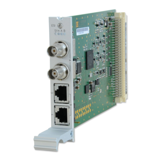
Page 11: Esi - Telecom Synchronisation References
flashing yellow, if only PPS off, if no signal LED B green, if Clock and Framed available flashing green, if only Clock available flashing yellow, if only Framed available off, if no signal IMS-ESI Setup Guide Date: 24th February 2020... - Page 12 Pin assignment of the RJ-45 jacks (input 3 + 4) Date: 24th February 2020 IMS-ESI Setup Guide...
-
Page 13: Esi Configuration Via Web Interface
An ESI card is, as the MRI card, dedicated to one specific clock module (depending on the slot it is installed in) and can be installed in both ESI as well as MRI slots. Configurable Inputs Input 1: The input 1 is dedicated to 1PPS (Pulse Per Second) synchronization. IMS-ESI Setup Guide Date: 24th February 2020... - Page 14 The maximum slip number can be selected in range between 0.5 – 3 cycles, with 1.5 as a default value. Input 3: accepts as input signal configurable frequencies from 1 kHz to 20 MHz. 2048 kHz is set as de- fault value. Date: 24th February 2020 IMS-ESI Setup Guide...
- Page 15 TNC will be allowed for synchronization, whereas signal coming from Synchronous Equipment Timing Source (SETS) will not be accepted. Sa Bits With Sa Bits you can select one of the Sa4 to Sa8 bits which is allocated for SSM quality messages. IMS-ESI Setup Guide Date: 24th February 2020...
Need help?
Do you have a question about the IMS-ESI and is the answer not in the manual?
Questions and answers