
Subscribe to Our Youtube Channel
Related Manuals for Meinberg IMS-GPS180


Summary of Contents for Meinberg IMS-GPS180
- Page 1 MANUAL IMS-GPS180 Setup Guide Hot-Plug Module 10th January 2018 Meinberg Radio Clocks GmbH & Co. KG...
-
Page 3: Table Of Contents
Meinberg GPS Antenna/Converter ........ -
Page 4: Imprint
1 Imprint 1 Imprint Meinberg Funkuhren GmbH & Co. KG Lange Wand 9, 31812 Bad Pyrmont / Germany Phone: + 49 (0) 52 81 / 93 09 - 0 Fax: + 49 (0) 52 81 / 93 09 - 30 Internet: http://www.meinberg.de... -
Page 5: Safety Instructions For Hot Pluggable Modules
• Place the module out of the box or after removal from the system with the component side to the top on a grounded and static-free surface. • Storage of an IMS module must be done in a dry place. • Installation or removal from hot-swap components only by authorized personnel! Date: 10th January 2018 IMS-GPS180 Setup Guide... -
Page 6: Additional Safety Hints
To ensure safe operation supply mains connected to this decice must be equipped with a fuse and a fault- current circuit breaker according to the applicable national standards for safe operation. The device must be connected to a protective earth with low grounding resistance according to the applicable national rules. IMS-GPS180 Setup Guide Date: 10th January 2018... -
Page 7: Cabling
Wiring or any other work done the connectors particularly when connectors are opened may never be carried out when the installation is energized. All connectors must be covered to prevent from accidental contact to life parts. ALWAYS ENSURE A PROPER INSTALLATION! Date: 10th January 2018 IMS-GPS180 Setup Guide... -
Page 8: Replacement Or Installation Of A Hot-Pluggable Ims Module
Make sure that the module is securely locked into the connector block before you fasten the two screws. Now you can put the installed module into operation. Attachment points of an 1U IMS system IMS-GPS180 Setup Guide Date: 10th January 2018... -
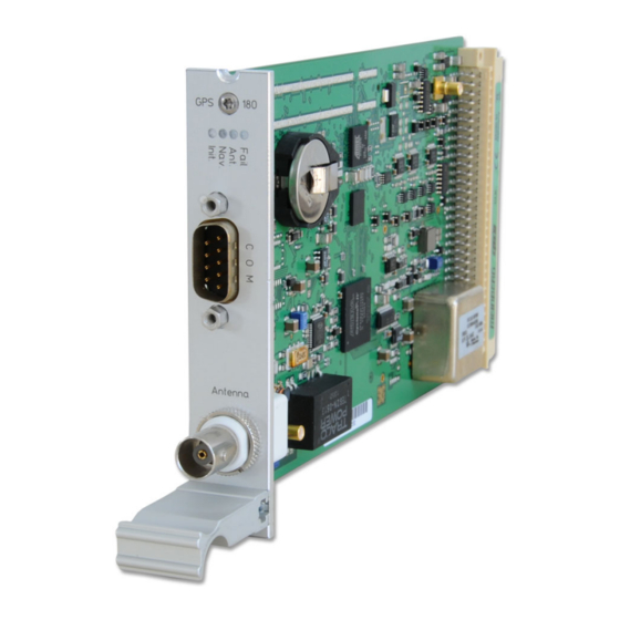
Page 9: Gps Clock
Nav.: green: positioning successfully Ant: red: antenna faulty or not connected yellow: the clock is synchronized by an external Signal - MRS mode (PPS, IRIG ...) Fail: red: time has not synchronized Date: 10th January 2018 IMS-GPS180 Setup Guide... - Page 10 Pin 2: CS (Chip Select) Pin 3: MOSI (Master Out, Slave In) Pin 4: MISO (Master In, Slave Out) Pin 5: GND Attention: Use this plug only to connect a MEIN- BERG IMS-XHE Rubidium expansion chassis. IMS-GPS180 Setup Guide Date: 10th January 2018...
-
Page 11: Configuration Of Ims Modules Via Web Interface
In case of a redundant receiver configuration the common settings for "IRIG In/Out", "Serial Ports", "Time Zone", "Enable Outputs", "Programmable Pulses" and "Synthesizers" appears into the "Switch Card" menu. Figure: Menu "Clock" in case of a single receiver Date: 10th January 2018 IMS-GPS180 Setup Guide... - Page 12 Step-Compensation Displays a hard time jump of the reference source (currently only available for PTP). Auto-Bias Time offset determined for the source versus an offset-free time source. IMS-GPS180 Setup Guide Date: 10th January 2018...
- Page 13 Here is an example how to configure a priority list in a descending order: 1. Source: GNSS / GPS 2. PPS + String 3. PTP – IEEE1588 4. external NTP Server Date: 10th January 2018 IMS-GPS180 Setup Guide...
- Page 14 - GPS / GNSS as the first priority has the highest estimated precision :100 ns - ext. Osc. (e.g. Rubidium): 120 ns - PTP IEEE 1588: 100 ns - PPS plus string: 100 ns - NTP: 100 us IMS-GPS180 Setup Guide Date: 10th January 2018...
- Page 15 ToD for one reference signal and phase for another. The reference sources you wish to use should be configured first in the Source Priority list. See MRS Settings MRS Source Priority. Here is one configuration example for Advanced Source Selection: Date: 10th January 2018 IMS-GPS180 Setup Guide...
- Page 16 The Trusted Source (TRS) feature is a powerful tool to protect the GNSS receiver from spoofing attacks. For the moment, the Trusted Source feature is supported only in combination with a Meinberg GPS or GNSS receiver and a Meinberg XHE external Rubidium holdover unit.
- Page 17 Time Scale: The output of the selected time code can be done with UTC or the local time. When "LOCAL TIME" is used, it refers to the configuration of the menu point "Time zone". Date: 10th January 2018 IMS-GPS180 Setup Guide...
- Page 18 If the system has the MRS "PPS plus string" option, the baudrate and framing for the incoming time string must be configured via this submenu. Meinberg Capture *only for specific units* This option is for systems that have a cap input. The event is triggered by a negative edge.
- Page 19 Enabling the Outputs Optionally, the outputs of the reference clock can be set to always supply a signal when the device is switched on, or only when the internal clock is running synchronously. Date: 10th January 2018 IMS-GPS180 Setup Guide...
- Page 20 Signal: Configuration of the output signal active in high or low. Disable output in Holdover mode: If the reference clock is asynchronous, the output signal is immediately deactivated when the checkbox is activated. IMS-GPS180 Setup Guide Date: 10th January 2018...
- Page 21 0.1. When the phase angle is increased, the delay of the output signal gets bigger. If a frequency higher than 10 kHz has been set, the phase cannot be changed. Date: 10th January 2018 IMS-GPS180 Setup Guide...
- Page 22 The signal propagation time of the antenna cable can be compensated by this value. The received time grid is delayed by approx. 5ns / m antenna cable. This time error is automatically compensated by entering the cable length. The default value is 20m. The maximum input value should not exceed 500m. IMS-GPS180 Setup Guide Date: 10th January 2018...
- Page 23 This also makes it possible to transmit other times, which have been entered via the menu item "Initialize the receiver", to the NTPD. In normal cases, the checkbox should remain empty. If this box is activated, the status "Simulation mode" is displayed under "Info of the receiver" in the main menu. Date: 10th January 2018 IMS-GPS180 Setup Guide...
- Page 24 This also makes it possible to transmit other times, which have been entered via the menu item "Initialize the receiver", to the NTPD. In normal cases, the checkbox should remain empty. If this box is activated, the status "Simulation mode" is displayed under "Info of the receiver" in the main menu. IMS-GPS180 Setup Guide Date: 10th January 2018...
- Page 25 "initialize Position". This option is useful when the system is operated at a different location and if started with the previously battery-buffered satellite data. Time/Date: With this function, the reference clock can manually be set to a specific date and time. Date: 10th January 2018 IMS-GPS180 Setup Guide...
- Page 26 4 GPS Clock Receiver Information This menu item lists all the important information and options of the reference clock. IMS-GPS180 Setup Guide Date: 10th January 2018...
- Page 27 Switch Card The RSC (SCU) switch card is an automatic multiplexer for redundant systems with two Meinberg radio clocks. The card is used for the automatic switching of the pulse and frequency outputs as well as the serial interfaces of the connected clocks. The selection of the respectively active system is made, based on the state of the clock’s generated TIME_SYNC signals, which show the synchronous state of the clocks.
-
Page 28: Meinberg Gps Antenna/Converter
4.2 Meinberg GPS Antenna/Converter 4.2.1 Introduction The Meinberg GPS antenna/converter unit combines a standard GPS patch antenna with a frequency converter which translates the original 1.5 GHz signal received from the GPS satellites to an intermediate frequency, so a standard coaxial cable type like RG58 can be used for antenna cable lengths up to 300 meters (1000 ft). If a low-loss cable type like RG213 is used then even 700 meters (2300 ft) between receiver and antenna are possible without requirement for an additional amplifier. -
Page 29: Mounting And Installation Of The Gps Antenna
Otherwise GPS reception may be degraded, or the GPS receiver can even be damaged. Date: 10th January 2018 IMS-GPS180 Setup Guide... -
Page 30: Powering Up A Gnss Receiver
GPS Satellites") as well as via the Web GUI ("Clock Receiver Information") you can check the number of satellites that are in view (i.e. above the horizon) and considered good (i.e. are healthy and can be tracked). IMS-GPS180 Setup Guide Date: 10th January 2018...
Need help?
Do you have a question about the IMS-GPS180 and is the answer not in the manual?
Questions and answers