Table of Contents
Advertisement
Quick Links
71M6521 Demo Board User's Manual
71M6521 Demo Board
Revision 2.18
USER'S MANUAL
TERIDIAN Semiconductor Corporation
6440 Oak Canyon Rd., Suite 100
Irvine, CA 92618-5201
Phone: (714) 508-8800 ▪ Fax: (714) 508-8878
http://www.teridian.com/
meter.support@teridian.com
© 2005-2009 TERIDIAN Semiconductor Corporation
4/16/2009 5:15:00 PM
Revision 2.18
Page: 1 of 111
Advertisement
Table of Contents

Related Manuals for Teridian 71M6521


Summary of Contents for Teridian 71M6521
- Page 1 71M6521 Demo Board User’s Manual 71M6521 Demo Board USER’S MANUAL 4/16/2009 5:15:00 PM Revision 2.18 TERIDIAN Semiconductor Corporation 6440 Oak Canyon Rd., Suite 100 Irvine, CA 92618-5201 Phone: (714) 508-8800 ▪ Fax: (714) 508-8878 http://www.teridian.com/ meter.support@teridian.com Revision 2.18 Page: 1 of 111...
- Page 2 71M6521 Demo Board User’s Manual TERIDIAN Semiconductor Corporation makes no warranty for the use of its products, other than expressly contained in the Company’s warranty detailed in the TERIDIAN Semiconductor Corporation standard Terms and Conditions. The company assumes no responsibility for any errors which may appear in this document, reserves the right to change devices or specifications detailed herein at any time without notice and does not make any commitment to update the information contained herein.
- Page 3 71M6521 Demo Board User’s Manual 71M6521 Single-Phase Energy Meter IC DEMO BOARD USER’S MANUAL Revision 2.18 Page: 3 of 111 © 2005-2009 TERIDIAN Semiconductor Corporation...
-
Page 4: Table Of Contents
1.9.4 Updating Calibration Data in EEPROM ...................... 34 1.9.5 Loading the 6521_demo.hex file into the Demo Board ................34 1.9.6 The Programming Interface of the 71M6521 ....................36 1.10 Demo Code ..............................36 1.10.1 Demo Code Description ..........................36 1.10.2 Demo Code Variations .......................... - Page 5 Debug Board Bill of Material ........................101 4.11 Debug Board Schematics ..........................102 4.12 Debug Board PCB Layout ..........................103 4.13 TERIDIAN 71M6521 Pin-Out Information ..................... 106 4.14 Modification History ............................111 Revision 2.18 Page: 5 of 111 © 2005-2009 TERIDIAN Semiconductor Corporation...
- Page 6 Figure 1-1: Demo Board: Basic Connections ....................... 10 Figure 1-2: Demo Board: Ribbon Cable Connections ....................11 Figure 1-3: The TERIDIAN 6521 Demo Board with Debug Board Block Diagram (CT Configuration) ......12 Figure 1-4: Port Configuration Setup ........................14 Figure 1-5: Hyperterminal Sample Window with Disconnect Button ..............
- Page 7 Figure 4-25: Debug Board: Middle Layer 2, Supply Plane ..................105 Figure 4-26: Debug Board: Bottom Trace Layer ....................105 Figure 4-27: TERIDIAN 71M6521 QFN68: Pinout (top view) ..................108 Figure 4-28: TERIDIAN 71M6521 LQFP64: Pinout (top view) ................... 109 List of Tables Table 1-1: Jumper settings on Debug Board ........................
- Page 8 71M6521 Demo Board User’s Manual Page: 8 of 111 Revision 2.18 © 2005-2009 TERIDIAN Semiconductor Corporation...
-
Page 9: Getting Started
Debug Board that allows a connection to a PC through a RS232 port. The Demo Board allows the evaluation of the 71M6521 energy meter controller chip for measurement accuracy and overall system use. -
Page 10: Compatibility
This manual applies to the following hardware and software revisions: 71M6521FE, chip revision A06 71M6521 chip memory configurations 71M6521BE (8KB), 71M6521DE (16KB), 71M6521FE (32KB) Demo D6521T4A7 (64-pin, REV 7.0), D6521T4A8 (64-pin, REV 8.0), and D6521T4A10 (64-pin, REV 10.0) Demo Kit firmware revision 4.7 and later... -
Page 11: Figure 1-2: Demo Board: Ribbon Cable Connections
Figure 1-2: Demo Board: Ribbon Cable Connections The 71M6521 Demo Board block diagram is shown in Figure 1-3. It consists of a stand-alone meter Demo Board and an optional Debug Board. The Demo Board contains all circuits necessary for operation as a meter, including display, calibration LED, and power supply. -
Page 12: Power Supply Setup
GND_DBG JP21 11/27/2006 Figure 1-3: The TERIDIAN 6521 Demo Board with Debug Board Block Diagram (CT Configuration) All analog input signals are referenced to the V3P3 (3.3V power supply to the chip). 1.6.1 POWER SUPPLY SETUP There are several choices for meter power supply: •... -
Page 13: Cable For Serial Connection
The number 3 in the leftmost digit indicates that accumulated Watt-hours are displayed. In the case shown above, 0.001 Wh were accumulated. The decimal dot in the leftmost segment will be blinking, indicating activity of the MPU inside the 71M6521. In Mission Mode, the display can be cycled by pressing the pushbutton (PB). -
Page 14: Serial Connection Setup For The Pc
71M6521 Demo Board User’s Manual 1.6.4 SERIAL CONNECTION SETUP FOR THE PC After connecting the DB9 serial port to a PC, start the HyperTerminal application (or any other suitable communication program) and create a session using the communication parameters shown in Table 1-4. -
Page 15: Using The Demo Board
Figure 1-5: Hyperterminal Sample Window with Disconnect Button USING THE DEMO BOARD The 71M6521 Demo Board is a ready-to-use meter prepared for use with an external current transformer. Using the Demo Board involves communicating with the Demo Code. An interactive command line interface (CLI) is available as part of the Demo Code (71M6521FE). -
Page 16: Cycling The Lcd Display
1.7.2 CYCLING THE LCD DISPLAY The Demo Codes for all versions of the 71M6521 Demo Board allow cycling of the display using the PB button. By briefly pressing the button, the next available parameter from Table 1-6 is selected. This makes it easy to navigate various displays for Demo Boards that do not have the CLI. -
Page 17: Serial Command Line Interface (Cli)
71M6521 Demo Board User’s Manual 1.7.3 SERIAL COMMAND LINE INTERFACE (CLI) > Once, communication to the Demo Board is established, press <CR> and the Demo Program prompt (“ ”) should appear. Type >i1 to verify that the Demo Program version is revision 4.7 or later. - Page 18 DIO or Configuration RAM space is the address range 0x2000 to 0x20FF. This RAM contains registers used for configuring basic hardware and functional properties of the 71M6521 and is organized in bytes (8 bits). The 0x2000 offset is automatically added when the command RI is typed.
- Page 19 71M6521 Demo Board User’s Manual Commands controlling the CE: COMPUTE ENGINE CONTROL Description: Allows the user to enable and configure the compute engine. Usage: C [option] [argument] Compute Engine Enable (1 Enable, 0 Disable) Command combinations: Select input n for TMUX output pin. Enter n in hex notation.
- Page 20 71M6521 Demo Board User’s Manual Commands for Controlling the Metering Values Shown on the LCD Display: METER DISPLAY CONTROL (LCD) Description: Allows user to select internal variables to be displayed. Usage: M [option]. [option] Command kWh Total Consumption (display wraps around at 999.999) combinations: Temperature (C°...
- Page 21 The Z command acts like a hardware reset. The energy accumulators in XRAM will retain their values. Commands for Controlling the LCD and Sleep Modes (when in Brownout Mode): POWER MODE CONTROL Description: Allows the user switch to LCD and Sleep mode when the 71M6521 is in Brownout mode. Usage: B [option] [value] Command...
-
Page 22: Communicating Via Intel Hex Records
71M6521 Demo Board User’s Manual 1.7.4 COMMUNICATING VIA INTEL HEX RECORDS Due to memory restrictions, the text-based command line interface contained in the 71M6521FE Demo Code is not available for the 71M6521BE and 71M6521DE Demo Codes. In addition, the 16KB version of the Demo Code stores the CE data in EEPROM (this saves valuable flash memory space). -
Page 23: Table 1-7: Fields Of A Hex Record
71M6521 Demo Board User’s Manual Field Name Characters Description Start code An ASCII colon (":") Byte count The count of the character pairs in the data field. The 2-byte address at which the data field is to be loaded into Address memory. -
Page 24: Table 1-8: Data (Command) Types
71M6521 Demo Board User’s Manual Code Function 00, 02 Write CE data record, contains data and 16-bit CE address (CE data RAM is located at 0x1000). End Of File (Quit) record, a file termination record. Contains no data. This record has to be the last line of the file, and only one record per file is permitted. -
Page 25: Table 1-10: Pre-Assembled Hex Records
71M6521 Demo Board User’s Manual When only a partial record is entered, the Demo Board will time out after around 30 seconds and then send <CR>< LF>. A number of pre-assembled hex records is supplied with the Demo Code. It is easier to send a pre-assem- bled record using the “send text file”... -
Page 26: Using The Battery Modes
1.7.5 USING THE BATTERY MODES The 71M6521 is in so-called Mission mode, as long as 3.3VDC is supplied to the V3P3SYS pin. If this voltage is below the minimum required operating voltage which is usually indicated by V1 < VBIAS, and if no battery is connected to the VBAT pin, the chip is powered off. - Page 27 BWMm – enters sleep mode for m minutes, then returns to Brownout mode In Sleep Mode, almost all functions are disabled. Only the RTC and the wakeup timer are still active. The wakeup signal from the timer and the pushbutton (SW2 on the Demo Board) take the 71M6521 back to Brownout mode.
-
Page 28: Using The Demo Board For Metering Functions
The current input scaling factor, i.e. the input current generating 177mVrms at the IA/IB/IC IMAX: input pins of the 71M6521. 177mV rms is equivalent to 250mV peak. The voltage input scaling factor, i.e. the voltage generating 177mVrms at the VA/VB/VC... -
Page 29: Adjusting The Demo Boards To Different Current Transformers And Voltage Dividers
Changing the resistors R24/R25, R106/R107 to a combined resistance of 2.115Ω (for each pair) will cause the desired voltage drop of 177mV appearing at the IA, or IB inputs of the 71M6521 IC. WRATE should be adjusted to achieve the desired Kh factor, as described in 1.8.2. -
Page 30: Connecting Demo Boards To A Shunt Resistor
71M6521 Demo Board User’s Manual Resolving for R , we get: = (VMAX / N) / 177mV = (600V / 30) / 177mV = 170.45 This divider ratio can be implemented, for example, with a combination of one 16.95kΩ and one 100Ω... -
Page 31: Connecting Demo Board Revisions D6521T4A7, D6521T4A8, And D6521T4A10 To A Shunt Resistor
71M6521 Demo Board User’s Manual Important safety precautions apply when operating the Demo Board in shunt mode: In shunt configuration, the whole Demo Board will be at line voltage! Touching the board or any components must be avoided! It is highly recommended to isolate Demo Board and Debug Board (when used) and to provide separate power supplies for the Demo Board and Debug Board. -
Page 32: Adapting Demo Code Parameters To Operation With Shunt Resistor
Regardless of the calibration procedure used, parameters (calibration constants) will result that will have to be applied to the 71M6521 chip in order to make the chip apply the modified gains and phase shifts necessary for accurate operation. Table 1-11 shows the names of the calibration constants, their function, and their location in the CE RAM. -
Page 33: Updating The 6521_Demo.hex File
To merge macro.txt and old_6521_demo.hex into new_6521_demo.hex, use the command: d_merge old_6521_demo.hex macro.txt new_6521_demo.hex The new hex file can be written to the 71M6521 through the ICE port using the ADM51 in-circuit emulator. This step makes the calibration to the meter permanent. 1.9.3 CALIBRATION MACRO FILE The macro file in Figure 1-10 contains a sequence of commands to be used for Demo Boards that provide a serial command line interface (CLI). -
Page 34: Updating Calibration Data In Eeprom
Browse button. Once the file is selected, pressing the OK button will load the file into the flash memory of the 71M6521 IC. At this point, the emulator probe (cable) can be removed. Once the 71M6521 IC is reset using the reset button on the Demo Board, the new code starts executing. -
Page 35: Figure 1-11: Emulator Window Showing Reset And Erase Buttons
71M6521 Demo Board User’s Manual Figure 1-11: Emulator Window Showing Reset and Erase Buttons Figure 1-12: Emulator Window Showing Erased Flash Memory and File Load Menu Revision 2.18 Page: 35 of 111 © 2005-2009 TERIDIAN Semiconductor Corporation... -
Page 36: The Programming Interface Of The 71M6521
1.10.1 DEMO CODE DESCRIPTION The Demo Board is shipped preloaded with Demo Code revision 4.7 or later in the 71M6521 chip. The code revision can easily be verified by entering the command >i via the serial interface (see section 1.7.2). Check with your local TERIDIAN representative or FAE for the latest revision. -
Page 37: Demo Code Variations
Demo Board is for the 71M6521FE and for shunt/CT operation. When planning to develop code for a 71M6521 meter IC with smaller flash size, it can be useful to load the Demo Codes that were written for the smaller flash sizes into the 71M6521FE IC. - Page 38 71M6521 Demo Board User’s Manual L in Name Purpose Function or LSB Value Format XDATA bits Starting current, SQSUM unsigned 0x0000 IThrshldA element A 0 in this location disables creep logic for both element A and B. The default value is 241610. The current threshold...
- Page 39 71M6521 Demo Board User’s Manual L in Name Purpose Function or LSB Value Format XDATA bits Vcal Voltage value to be Nominal RMS voltage applied to unsigned 0x0021 used for auto- all elements during auto- calibration** calibration (LSB = 0.1V).
- Page 40 71M6521 Demo Board User’s Manual L in Name Purpose Function or LSB Value Format XDATA bits Vrms, element B**,† SQSUM unsigned 0x0053 Vrms_B Irms, element B SQSUM unsigned 0x0057 Irms_B Status of meter See table for STATUS register unsigned 0x0063...
-
Page 41: Table 1-13: Mpu Memory Locations (71M6521De/Fe)
71M6521 Demo Board User’s Manual L in Name Purpose Function or LSB Value Format XDATA bits MainEdgeCnt Count of voltage zero count unsigned 0x014B crossings Default sum of Wh, LSB of W0SUM signed 0x014F nonvolatile Wh, element A, “ signed... -
Page 42: Table 1-14: Values For Pulse Source Registers
71M6521 Demo Board User’s Manual Table 1-14 lists the possible entries for the PULSEWSOURCE and PULSEVSOURCE registers. Decimal Value in Decimal Value in Selected Pulse Source Selected Pulse Source PULSEWSOURCE, PULSEWSOURCE, PULSEVSOURCE PULSEVSOURCE EQU= 0 : W0SUM if W0SUM > W1SUM, W1SUM (reserved) if W1SUM >... -
Page 43: Table 1-15: Status Register
71M6521 Demo Board User’s Manual Table 1-15 explains the bits of the STATUS register. Significance Significance CREEP BATTERY_BAD, voltage below VBatMin PB_PRESS, wake pushbutton CAL_BAD (Checksum over calibration was pressed factors is invalid) WAKE_ALARM CLOCK_UNSET (Clock is not set) POWER_BAD (checksums for both... -
Page 44: Ce Code Memory Locations (71M6521De/Fe)
71M6521 Demo Board User’s Manual 1.10.5 CE CODE MEMORY LOCATIONS (71M6521DE/FE) All CE memory locations are listed in the 71M6521DE/FE data sheet. These locations are listed again in Table 1-16, along with the addresses used by the CLI and the physical addresses used by the hex records interface. -
Page 45: Ce Code Memory Locations (71M6521Be)
71M6521 Demo Board User’s Manual 0x75 0x11D4 VAR0SUM_X The sum of VAR samples from each wattmeter element (In_8 is the gain configured by IA_SHUNT or IB_SHUNT). 0x71 0x11C4 VAR1SUM_X 0x76 0x11D8 W0SUM_X The sum of Watt samples from each wattmeter element (In_8 is the gain configured by IA_SHUNT or IB_SHUNT). -
Page 46: Table 1-17: Ce Memory Locations (71M6521Be)
71M6521 Demo Board User’s Manual 0x1054 DEGSCALE This constant is used for the calculation of DELTA_T . This parameter is added to compensate for input noise and truncation in 0x1058 QUANT_IA the squaring calculations for I The reference temperature read from MPU location TEMP_RAW is 0x105C 7.04*10... -
Page 47: Some Mpu Code Memory Locations (71M6521Be)
71M6521 Demo Board User’s Manual 1.10.7 SOME MPU CODE MEMORY LOCATIONS (71M6521BE) There are no VMAX and IMAX parameters declared in the 6521BE Demo Code. The 6521BE Demo Code does not need these parameters, since it does not display voltage and current RMS values on the LCD. If necessary, the user can derive the values for register variables that depend on VMAX and IMAX by multi- plying the count in the registers with the LSB values given in Table 1-17. -
Page 48: Emulator Operation
For details on code development and test see the Software User’s Guide (SUG). The emulator can also be operated when the 71M6521 is in brownout mode. In brownout mode, the 71M6521 provides power for the pull-up resistors necessary for emulator operation via its V3P3D pin. -
Page 49: Application Information
71M6521 Demo Board User’s Manual APPLICATION INFORMATION CALIBRATION THEORY A typical meter has phase and gain errors as shown by φ , and A in Figure 2-1. Following the typical meter convention of current phase being in the lag direction, the small amount of phase lead in a typical current sensor is represented as -φ... - Page 50 71M6521 Demo Board User’s Manual From the voltage measurement, we determine that 1. We use the other two measurements to determine φ and A φ − cos( φ − − cos( cos( φ cos( φ φ − − cos( cos( −...
-
Page 51: Calibration With Five Measurements
71M6521 Demo Board User’s Manual And we calculate the new calibration current gain coefficient, including compensation for a slight gain increase in the phase calibration circuit. − − − π − − PHADJ PHADJ cos( − π − − −... -
Page 52: Fast Calibration
71M6521 Demo Board User’s Manual − φ − 12. tan( , and φ Now that we know the A errors, we calculate the new calibration voltage gain coefficient from the previous ones: We calculate PHADJ from φ... -
Page 53: Calibration Procedures
It is essential for a valid meter calibration to have the voltage stabilized a few seconds before the current is applied. This enables the Demo Code to initialize the 71M6521 and to stabilize the PLLs and filters in the CE. This method of operation is consistent with meter applications in the field as well as with metering standards. -
Page 54: Calibration Procedure With Three Measurements
The calibration procedures described below should be followed after interfacing the voltage and current sensors to the 71M6521 chip. When properly interfaced, the V3P3 power supply is connected to the meter neutral and is the DC reference for each input. Each voltage and current waveform, as seen by the 6521, is scaled to be less than 250mV (peak). -
Page 55: Procedure For Fast Calibration
Store the new calibration factors CAL_IA, CAL_VA, and PHADJ_A in the EEPROM of the meter. If the calibration is performed on a TERIDIAN Demo Board, the methods shown in sections 1.9.2 can be used. 2.2.4 PROCEDURE FOR FAST CALIBRATION The calibration procedure is as follows: Establish load voltage and current. -
Page 56: Figure 2-3: Calibration Spreadsheet For Three Measurements
71M6521 Demo Board User’s Manual Figure 2-3: Calibration Spreadsheet for Three Measurements Figure 2-4: Calibration Spreadsheet for Five Measurements Page: 56 of 111 Revision 2.18 © 2005-2009 TERIDIAN Semiconductor Corporation... -
Page 57: Compensating For Non-Linearities
71M6521 Demo Board User’s Manual Figure 2-5: Calibration Spreadsheet for Fast Calibration 2.2.6 COMPENSATING FOR NON-LINEARITIES Nonlinearity is most noticeable at low currents, as shown in Figure 2-6, and can result from input noise and truncation. Nonlinearities can be eliminated using the QUANT variable. -
Page 58: Calibrating Meters With Combined Ct And Shunt Resistor
Figure 2-7. In this configuration, the shunt resistor is connected to the IA channel while the current transformer is connected to the IB channel of the 71M6521. Calibrating this arrangement requires a few extra steps above the regular calibration. The calibration procedure applies to the sensor arrangement described above (SHUNT = IA, CT = IB). -
Page 59: Figure 2-7: 71M6521 With Shunt And Ct
LIVE LOAD 71M6521 NEUT 71M6511 V3P3 Figure 2-7: 71M6521 with Shunt and CT Calibrating for Shunt Resistor (Channel A): Calculate IMAX for the shunt resistor (IMAX_SHUNT). This can be done by using the following formula: IMAX_SHUNT = Vi The Vi value is the maximum analog input voltage for the channel, typically 177mV (RMS), and is the resistance value of the shunt resistor. -
Page 60: Table 2-1: Calibration Summary
71M6521 Demo Board User’s Manual Calibration for CT (Channel B): Compute IMAX for the CT channel (IMAX_CT), based on the CT turns ratio N and the termination resistor value R using the formula: IMAX_CT = 177mV* N / R This value is used in the following step as IMAX_CT. -
Page 61: Schematic Information
The oscillator of the 71M6521 drives a standard 32.768kHz watch crystal (see Figure 2-9). Crystals of this type are accurate and do not require a high current oscillator circuit. The oscillator in the 71M6521 has been designed specifically to handle watch crystals and is compatible with their high impedance and limited power handling capability. -
Page 62: Eeprom
Figure 2-11. DIO5 connects to both the DI and DO pins of the three-wire device. The CS pin must be connected to a vacant DIO pin of the 71M6521. A pull-up resistor of roughly 3kΩ to V3P3 should be used for the DI/DO signals, and the CS pin should be pulled down with a resistor to prevent that the three-wire device is selected on power-up, before the 71M6521 can establish a stable signal for CS. -
Page 63: Optical Interface
2.3.6 OPTICAL INTERFACE The 71M6521 IC is equipped with two pins supporting the optical interface: OPT_TX and OPT_RX. The OPT_TX pin can be used to drive a visual or IR light LED with up to 20mA, a series resistor (R in Figure 2-13) helps limiting the current). -
Page 64: Reset And Pb Switches
71M6521 Demo Board User’s Manual V3P3 OPT_TX OPT_TX_OUT OPT_RX HDR5x1 OPTICAL I/F Figure 2-14: Optical Port Circuitry on the Demo Board 2.3.7 RESET AND PB SWITCHES If not used, the RESET and PB pins should be connected to DGND either directly or via a resistor, as shown in Figure 2-15. -
Page 65: Operation With Batteries
RTC, when board power is not present. Many meter manufacturers assemble the meter PCB with the 71M6521 IC and the other electronic components first and then join the meter PCB with the meter enclosure, sensors and other main components separately at a later production step. -
Page 66: Testing The Demo Board
71M6521 Demo Board User’s Manual TESTING THE DEMO BOARD This section will explain how the 71M6521 IC and the peripherals can be tested. Hints given in this section will help evaluating the features of the Demo Board and understanding the IC and its peripherals. -
Page 67: Eeprom
71M6521 Demo Board User’s Manual Figure 2-19: Calibration System Screen 2.4.2 EEPROM Testing the EEPROM provided on the Demo Board is straightforward and can be done using the serial command line interface (CLI) of the Demo Code. To write a string of text characters to the EEPROM and read it back, we apply the following sequence of CLI commands: >EEC1... -
Page 68: Rtc
2.4.4 HARDWARE WATCHDOG TIMER The hardware watchdog timer of the 71M6521 is disabled when the voltage at the V1 pin is at 3.3V (V3P3). On the Demo Boards, this is done by plugging in a jumper at TP10 between the V1 and V3P3 pins. Con- versely, removing the jumper at TP10 will enable the hardware watchdog timer. -
Page 69: Supply Current Measurements
The jumper on JP4 should be moved to position 1-2 in order to save the current required to supply the ICE_E pin. TERIDIAN APPLICATION NOTES Below is a list of Teridian Applications Notes that are relevant to the 71M6521. They can be obtained on the Teridian web site: •... - Page 70 71M6521 Demo Board User’s Manual Page: 70 of 111 Revision 2.18 © 2005-2009 TERIDIAN Semiconductor Corporation...
-
Page 71: Hardware Description
This 3-pin header allows selection of the battery mode operation: A jumper across pins 1-2 indicates that no external battery is available. The 71M6521 will stay in brownout mode when system power is down and it will communicate at 9600bd. -
Page 72: Table 3-1: D6521N12A7 Demo Board Description
This is the NEUTRAL line voltage input. It is connected to the 3.3V NEUTRAL net of the 71M6521. The neutral wire is connected to the spade terminal on the bottom of the board. This is the line voltage input that feeds both the resistor divider VA_IN leading to the VA pin on the chip and the internal power supply. -
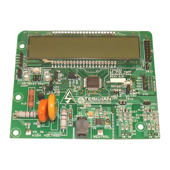
Page 73: Figure 3-1: 71M6521T4A7 Demo Board Connectors, Jumpers, Switches, And Test Points
71M6521 Demo Board User’s Manual Figure 3-1: 71M6521T4A7 Demo Board Connectors, Jumpers, Switches, and Test Points Revision 2.18 Page: 73 of 111 © 2005-2009 TERIDIAN Semiconductor Corporation... -
Page 74: Demo Board Hardware Specifications
71M6521 Demo Board User’s Manual DEMO BOARD HARDWARE SPECIFICATIONS PCB Dimensions Dimensions 4.5” x 3.8” (114.3mm x 96.5mm) Thickness 0.062” (1.6mm) Height w/ components 2.0” (51mm) Environmental Operating Temperature -40°…+85°C (function of crystal oscillator affected outside –10°C to +60°C) ... -
Page 75: Changes To The D6521T4A7
(1,000pF) for the TFP-2 Flash Programming Device at the programming headers J 15 (pin #6) and J14 (pin #2). These pins allow the TFP-2 to reset the 71M6521 chip after a flash erase operation using the watchdog- timeout mechanism, allowing flash memory parts with the SECURE bit set (see the data sheet for more information) to be erased and reprogrammed. -
Page 76: D6521T4A10: Features
71M6521 Demo Board User’s Manual D6521T4A10: FEATURES 3.4.1 D6521T4A10 FEATURE SUMMARY The features added to the D6521T4A10 Demo Board are: Circuitry was added that supports features required for the India market. J14 was removed. The 6-pin header J15 is the only programming connector available on the board. An adapter that enables the transition from the AMP/Tyco connector used for the ADM51 ICE or for the TFP2 programmer to the 6-pin header J15 is supplied with the Demo Kit. -
Page 77: D6521T4A10 Features For The India Market
71M6521 Demo Board User’s Manual 3.4.2 D6521T4A10 FEATURES FOR THE INDIA MARKET Several India-specific features were added to the D6521T4A10 Demo Board to support the detection of tamper attempts. These features are: A 2-pin header (TP1) is provided that allows the connection of a “neutral-missing” transformer. This transformer normally provides enough output voltage and current to supply the Demo Board in case the main AC supply is disconnected. -
Page 78: Appendix
71M6521 Demo Board User’s Manual APPENDIX Demo Board Description This appendix includes the following documentation, tables and drawings for the, D65214A7, D65214A8, and D6521T4A10 Demo Boards: Schematics Bills of Materials (Parts Lists) PCB Layout Views Debug Board Description ... -
Page 79: 64-Pin Demo Board Electrical Schematic (D6521T4A7)
R107 1000pF 1000PF 1000pF 1000pF BAV99DW V3P3 TERIDIAN SEMICONDUCTOR CORP. Title 71M6521 Demo Board Schematic SMT 64 Pin Package MOUNT Size Document Number D6521T4A7 Date: Tuesday , April 17, 2007 Sheet Figure 4-1: D6521T4A7 Demo Board: Electrical Schematic 1/2 Revision 2.18 Page: 79 of 111 ©... -
Page 80: Figure 4-2: D6521T4A7 Demo Board: Electrical Schematic 2/2
OPT_RX OPT_RX/DIO1 V3P3 100pF 6521-TQFP TERIDIAN SEMICONDUCTOR CORP. 1000pF Title 71M6521 Demo Board Schematic SMT 64 Pin Package Size Document Number D6521T4A7 Date: Tuesday , April 17, 2007 Sheet Figure 4-2: D6521T4A7 Demo Board: Electrical Schematic 2/2 Page: 80 of 111 Revision 2.18... -
Page 81: 64-Pin Demo Board Electrical Schematic (D6521T4A8)
B. V3P3 Make C18 and C21 100pF if TERIDIAN SEMICONDUCTOR CORP. channel B is used for Title current shunt. 71M6521 Demo Board Schematic SMT 64 Pin Package MOUNT Size Document Number D6521T4A8 Date: Thursday , January 31, 2008... -
Page 82: Figure 4-4: D6521T4A8 Demo Board: Electrical Schematic 2/2
OPT_RX OPT_RX/DIO1 V3P3 100pF TERIDIAN SEMICONDUCTOR CORP. 1000pF 6521-TQFP Title 71M6521 Demo Board Schematic SMT 64 Pin Package Size Document Number D6521T4A8 Date: Thursday , January 31, 2008 Sheet Figure 4-4: D6521T4A8 Demo Board: Electrical Schematic 2/2 Page: 82 of 111 Revision 2.18... -
Page 83: 64-Pin Demo Board Electrical Schematic (D6521T4A10)
B. V3P3 Make C18 and C21 100pF if TERIDIAN SEMICONDUCTOR CORP. channel B is used for Title current shunt. 71M6521 Demo Board Schematic SMT 64 Pin Package L16 600 OHM GND_2 MOUNT Size Document Number D6521T4A10 Date:... -
Page 84: Figure 4-6: D6521T4A10 Demo Board: Electrical Schematic 2/3
GND_2 100pF 1000pF NEUTRAL TERIDIAN SEMICONDUCTOR CORP. 6521-TQFP XTAL_GND Title 71M6521 Demo Board Schematic SMT 64 Pin Package NOTE DIO8: Size Document Number INDIA REF. POWERMODE: REMOVE R154 AND JP12. D6521T4A10 NORMAL DEMO BOARD BATTERY MODE: REMOVE V3P3_NM CIRCUIT. Date:... -
Page 85: Figure 4-7: D6521T4A10 Demo Board: Electrical Schematic 3/3
71M6521 Demo Board User’s Manual NEUTRAL_2 TP18 V3P3 NEUTRAL 816-RI-07A REEDSWITCH SEG28/DIO8 MAG_TMP SOT23 SMBT2222AE6327 GND_2 V3P3_NM NEUTRAL_2 600 OHM BAV99,SOT-23 600 OHM V3P3_NM 1N4148W-TP,SOD-123 1000pF 4.7V, SOD-123 BAV99,SOT-23 GND_2 100uF ELECTROLY TIC 600 OHM Figure 4-7: D6521T4A10 Demo Board: Electrical Schematic 3/3 Revision 2.18... -
Page 86: D6521T4A7 Demo Board Bill Of Material
71M6521 Demo Board User’s Manual D6521T4A7 DEMO BOARD BILL OF MATERIAL Digi-Key/Mouser Part Item Reference Part Footprint Number Part Number Manufacturer 2200uF radial P5143-ND ECA-1CM222 Panasonic C2,C4,C22 10uF RC1812 478-1672-1-ND TAJB106K010R RC0603 PCC2224CT-ND ECJ-1VB1C105K Panasonic C5,C17,C19,C20,C23,C28, 0.1uF RC0603 445-1314-1-ND C1608X7R1H104K... -
Page 87: D6521T4A8 Demo Board Bill Of Material
71M6521 Demo Board User’s Manual D6521T4A8 DEMO BOARD BILL OF MATERIAL Digi-Key/Mouser Part Item Reference Part Part Number Manufacturer Footprint Number 2200uF radial P5143-ND ECA-1CM222 Panasonic C2,C4,C22 10uF RC1812 478-1672-1-ND TAJB106K010R RC0603 PCC2224CT-ND ECJ-1VB1C105K Panasonic C5,C11,C17,C19,C23,C28 0.1uF RC0603 445-1314-1-ND C1608X7R1H104K... -
Page 88: D6521T4A10 Demo Board Bill Of Material
71M6521 Demo Board User’s Manual D6521T4A10 DEMO BOARD BILL OF MATERIAL Digi-Key/Mouser Part Item Reference Part PCB Footprint Part Number Manufacturer Number BT1,BT2 Battery 2200uF radial P5143-ND ECA-1CM222 Panasonic C2,C4,C22 10uF RC1812 478-1672-1-ND TAJB106K010R RC0603 PCC2224CT-ND ECJ-1VB1C105K Panasonic C5,C17,C19,C23,C28,C37 0.1uF... -
Page 89: D6521T4A7 Demo Board Pcb Layout
71M6521 Demo Board User’s Manual D6521T4A7 DEMO BOARD PCB LAYOUT Figure 4-8: D6521T4A7 Demo Board: Top View Revision 2.18 Page: 89 of 111 © 2005-2009 TERIDIAN Semiconductor Corporation... -
Page 90: Figure 4-9: D6521T4A7 Demo Board: Top Copper
71M6521 Demo Board User’s Manual Figure 4-9: D6521T4A7 Demo Board: Top Copper Page: 90 of 111 Revision 2.18 © 2005-2009 TERIDIAN Semiconductor Corporation... -
Page 91: Figure 4-10: D6521T4A7 Demo Board: Bottom View
71M6521 Demo Board User’s Manual Figure 4-10: D6521T4A7 Demo Board: Bottom View Revision 2.18 Page: 91 of 111 © 2005-2009 TERIDIAN Semiconductor Corporation... -
Page 92: Figure 4-11: D6521T4A7 Demo Board: Bottom Copper
71M6521 Demo Board User’s Manual Figure 4-11: D6521T4A7 Demo Board: Bottom Copper Page: 92 of 111 Revision 2.18 © 2005-2009 TERIDIAN Semiconductor Corporation... -
Page 93: D6521T4A8 Demo Board Pcb Layout
71M6521 Demo Board User’s Manual D6521T4A8 DEMO BOARD PCB LAYOUT Figure 4-12: D6521T4A8 Demo Board: Top View Revision 2.18 Page: 93 of 111 © 2005-2009 TERIDIAN Semiconductor Corporation... -
Page 94: Figure 4-13: D6521T4A8 Demo Board: Top Copper
71M6521 Demo Board User’s Manual Figure 4-13: D6521T4A8 Demo Board: Top Copper Page: 94 of 111 Revision 2.18 © 2005-2009 TERIDIAN Semiconductor Corporation... -
Page 95: Figure 4-14: D6521T4A8 Demo Board: Bottom View
71M6521 Demo Board User’s Manual Figure 4-14: D6521T4A8 Demo Board: Bottom View Revision 2.18 Page: 95 of 111 © 2005-2009 TERIDIAN Semiconductor Corporation... -
Page 96: Figure 4-15: D6521T4A8 Demo Board: Bottom Copper
71M6521 Demo Board User’s Manual Figure 4-15: D6521T4A8 Demo Board: Bottom Copper Page: 96 of 111 Revision 2.18 © 2005-2009 TERIDIAN Semiconductor Corporation... -
Page 97: D6521T4A10 Demo Board Pcb Layout
71M6521 Demo Board User’s Manual D6521T4A10 DEMO BOARD PCB LAYOUT Figure 4-16: D6521T4A10 Demo Board: Top View Revision 2.18 Page: 97 of 111 © 2005-2009 TERIDIAN Semiconductor Corporation... -
Page 98: Figure 4-17: D6521T4A10 Demo Board: Top Copper
71M6521 Demo Board User’s Manual Figure 4-17: D6521T4A10 Demo Board: Top Copper Page: 98 of 111 Revision 2.18 © 2005-2009 TERIDIAN Semiconductor Corporation... -
Page 99: Figure 4-18: D6521T4A10 Demo Board: Bottom Copper
71M6521 Demo Board User’s Manual Figure 4-18: D6521T4A10 Demo Board: Bottom Copper Revision 2.18 Page: 99 of 111 © 2005-2009 TERIDIAN Semiconductor Corporation... -
Page 100: Figure 4-19: D6521T4A10 Demo Board: Bottom View
71M6521 Demo Board User’s Manual Figure 4-19: D6521T4A10 Demo Board: Bottom View Page: 100 of 111 Revision 2.18 © 2005-2009 TERIDIAN Semiconductor Corporation... -
Page 101: Debug Board Bill Of Material
71M6521 Demo Board User’s Manual 4.10 DEBUG BOARD BILL OF MATERIAL Item Reference Value PCB Footprint Manufacturer Vendor Vendor P/N C1-C3,C5-C10,C12-C23 0.1uF 0805 C2012X7R1H104K Digi-Key 445-1349-1-ND 33uF/10V 1812 TAJB336K010R Digi-Key 478-1687-1-ND 10uF/16V, B Case 1812 TAJB106K016R Digi-Key 478-1673-1-ND D2,D3 0805... -
Page 102: Debug Board Schematics
71M6521 Demo Board User’s Manual 4.11 DEBUG BOARD SCHEMATICS V5_DBG 0.1uF 0.1uF GND_DBG V3P3 VDD1 VDD2 V5_DBG GND2 DIO02 VDD1 DOUT GND_DBG GND1 GND2 V5_DBG V5_DBG 5Vdc EXT SUPPLY DISPLAY SEL ADUM1100 GND_DBG 0.1uF GND_DBG V5_DBG 33uF, 10V 0.1uF RAPC712 GND_DBG 0.1uF... -
Page 103: Debug Board Pcb Layout
71M6521 Demo Board User’s Manual 4.12 DEBUG BOARD PCB LAYOUT Figure 4-21: Debug Board: Top View Figure 4-22: Debug Board: Bottom View Revision 2.18 Page: 103 of 111 © 2005-2009 TERIDIAN Semiconductor Corporation... -
Page 104: Figure 4-23: Debug Board: Top Signal Layer
71M6521 Demo Board User’s Manual Figure 4-23: Debug Board: Top Signal Layer Figure 4-24: Debug Board: Middle Layer 1, Ground Plane Page: 104 of 111 Revision 2.18 © 2005-2009 TERIDIAN Semiconductor Corporation... -
Page 105: Figure 4-25: Debug Board: Middle Layer 2, Supply Plane
71M6521 Demo Board User’s Manual Figure 4-25: Debug Board: Middle Layer 2, Supply Plane Figure 4-26: Debug Board: Bottom Trace Layer Revision 2.18 Page: 105 of 111 © 2005-2009 TERIDIAN Semiconductor Corporation... -
Page 106: Teridian 71M6521 Pin-Out Information
GNDA. It is important to minimize the capacitance XOUT between these pins. See the crystal manufacturer datasheet for details. Table 4-5: 71M6521 Pin Description 1/2 Page: 106 of 111 Revision 2.18 © 2005-2009 TERIDIAN Semiconductor Corporation... -
Page 107: Table 4-6: 71M6521 Pin Description 2/2
SLEEP or LCD mode. PB does not have an internal pull-up or pull-down. If unused, this pin must be terminated to GNDD. X4MHz This pin must be connected to GNDD. Table 4-6: 71M6521 Pin Description 2/2 Revision 2.18 Page: 107 of 111 © 2005-2009 TERIDIAN Semiconductor Corporation... -
Page 108: Figure 4-27: Teridian 71M6521 Qfn68: Pinout (Top View)
COM2 SEG17 COM3 SEG16 18 19 20 21 22 23 24 25 26 27 28 29 30 31 32 33 34 Figure 4-27: TERIDIAN 71M6521 QFN68: Pinout (top view) Page: 108 of 111 Revision 2.18 © 2005-2009 TERIDIAN Semiconductor Corporation... -
Page 109: Figure 4-28: Teridian 71M6521 Lqfp64: Pinout (Top View)
SEG29/DIO9 TERIDIAN CKTEST/SEG19 SEG28/DIO8 SEG27/DIO7 V3P3SYS SEG4 SEG26/DIO6 71M6521FE-IGT SEG5 SEG25/DIO5 SEG37/DIO17 SEG24/DIO4 COM0 ICE_E COM1 SEG18 SEG17 COM2 COM3 SEG16 Figure 4-28: TERIDIAN 71M6521 LQFP64: Pinout (top view) Revision 2.18 Page: 109 of 111 © 2005-2009 TERIDIAN Semiconductor Corporation... - Page 110 71M6521 Demo Board User’s Manual Page: 110 of 111 Revision 2.18 © 2005-2009 TERIDIAN Semiconductor Corporation...
-
Page 111: Modification History
Added alternative method for determining QUANT in section 2.2.6. User Manual: This User Manual contains proprietary product definition information of TERIDIAN Semiconductor Corporation (TSC) and is made available for informational purposes only. TERIDIAN assumes no obligation regarding future manufacture, unless agreed to in writing. - Page 112 Mouser Electronics Authorized Distributor Click to View Pricing, Inventory, Delivery & Lifecycle Information: Maxim Integrated 71M6521FE-DB...
Need help?
Do you have a question about the 71M6521 and is the answer not in the manual?
Questions and answers