Teridian 73S1210F User Manual
Evaluation board lite
Hide thumbs
Also See for 73S1210F:
- User manual (30 pages) ,
- Quick start manual (2 pages) ,
- User manual (29 pages)
Table of Contents
Advertisement
Quick Links
Download this manual
See also:
User Manual
Advertisement
Table of Contents

Related Manuals for Teridian 73S1210F


Summary of Contents for Teridian 73S1210F
- Page 1 73S1210F Evaluation Board Lite User Guide August 18, 2009 Rev. 1.1 UG_1210F_044 www.BDTIC.com/maxim...
- Page 2 Ltd. All other trademarks are the property of their respective owners. Teridian Semiconductor Corporation makes no warranty for the use of its products, other than expressly contained in the Company’s warranty detailed in the Teridian Semiconductor Corporation standard Terms and Conditions. The company assumes no responsibility for any errors which may appear in this document, reserves the right to change devices or specifications detailed herein at any time without notice and does not make any commitment to update the information contained herein.
-
Page 3: Table Of Contents
Figure 3: Emulator Window Showing RESET and ERASE Buttons ............8 Figure 4: Emulator Window Showing Erased Flash Memory and File Load Menu ........8 Figure 5: 73S1210F Evaluation Board Lite Jumper, Switch and Test Point Locations ......12 Figure 6: 73S1210F Evaluation Board Lite Electrical Schematic ............. 13 Figure 7: 73S1210F Evaluation Board Lite Top View (Silkscreen) ............ -
Page 4: Introduction
1 Introduction The Teridian Semiconductor Corporation (TSC) 73S1210F Evaluation Board- Lite is used to demonstrate the capabilities of the 73S1210F Smart Card Controller device. It has been designed to operate either as a standalone or as a development platform. The 73S1210F Evaluation Board Lite can be programmed to run any of the Teridian turnkey applications or a user-developed custom application. -
Page 5: Evaluation Board Lite Package Contents
ICE/Programmer interface • ON/OFF switch • 1 LED Recommended Equipment and Test Tools The following equipment and tools (not provided) are recommended for use with the 73S1210F Evaluation Board Lite package: • ® ® ® For functional evaluation: PC with Microsoft... -
Page 6: Evaluation Board Lite Setup
Evaluation Board Lite with the external equipment. The power supply input (VBAT) provides back-up power for those applications capable of using it. When a power supply is connected to VBAT, the ON/OFF switch, S2, turns the power supply to the 73S1210F on or off. -
Page 7: Using The Evaluation Board Lite With An Emulation Tool
Loading Code with the In-Circuit Emulator If firmware exists in the 73S1210F flash memory, the memory must be erased before loading a new file into memory. In order to erase the flash memory, the RESET button in the emulator software must be... -
Page 8: Figure 3: Emulator Window Showing Reset And Erase Buttons
RESET BUTTON ERASE BUTTON Figure 3: Emulator Window Showing RESET and ERASE Buttons Figure 4: Emulator Window Showing Erased Flash Memory and File Load Menu www.BDTIC.com/maxim... -
Page 9: Using The Pccid Application
3 Using the PCCID Application The PCCID firmware is pre-installed on the 73S1210F Evaluation Board. It requires a PC with the serial RS-232 port. When powered-up, the board is able to run the PCCID demonstration host application which allows: •... -
Page 10: Evaluation Board Lite Hardware Description
4 Evaluation Board Lite Hardware Description Jumpers, Switches and Test Points Table 2 describes the 73S1210F Evaluation Board Lite jumpers, switches and test points. The Item # in Table 2 references Figure 5. The Default Setting column refers to setup for running PCCID application. - Page 11 Test point to monitor VPC. VPC is the input power source to the internal voltage converter. This voltage is derived from either VBUS or VBAT. See the 73S1210F datasheet for further information. Smart Card connector Allows the evaluation board to communicate with a smart card using a standard (credit card size) format.
-
Page 12: Figure 5: 73S1210F Evaluation Board Lite Jumper, Switch And Test Point Locations
Figure 5: 73S1210F Evaluation Board Lite Jumper, Switch and Test Point Locations www.BDTIC.com/maxim... -
Page 13: Schematic
VBUS VBUS VBUS VBUS 100k +5VDC C30, C31 and C32 VBUS_MON should be as MOUNT HOLES FOR STAND OFFS close as possible Enable 0.1uF to VDD pins on U4 USB_CONN_4 200k Figure 6: 73S1210F Evaluation Board Lite Electrical Schematic www.BDTIC.com/maxim... -
Page 14: Pcb Layouts
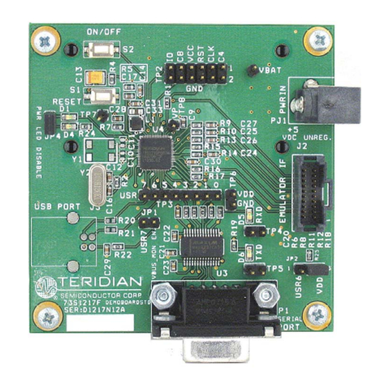
PCB Layouts Figure 7: 73S1210F Evaluation Board Lite Top View (Silkscreen) www.BDTIC.com/maxim... -
Page 15: Figure 8: 73S1210F Evaluation Board Lite Bottom View (Silkscreen)
Figure 8: 73S1210F Evaluation Board Lite Bottom View (Silkscreen) www.BDTIC.com/maxim... -
Page 16: Figure 9: 73S1210F Evaluation Board Lite Top Signal Layer
Figure 9: 73S1210F Evaluation Board Lite Top Signal Layer www.BDTIC.com/maxim... -
Page 17: Figure 10: 73S1210F Evaluation Board Lite Middle Layer 1 - Ground Plane
Figure 10: 73S1210F Evaluation Board Lite Middle Layer 1 – Ground Plane www.BDTIC.com/maxim... -
Page 18: Figure 11: 73S1210F Evaluation Board Lite Middle Layer 2 - Supply Plane
Figure 11: 73S1210F Evaluation Board Lite Middle Layer 2 – Supply Plane www.BDTIC.com/maxim... -
Page 19: Figure 12: 73S1210F Evaluation Board Lite Bottom Signal Layer
Figure 12: 73S1210F Evaluation Board Lite Bottom Signal Layer www.BDTIC.com/maxim... -
Page 20: Bill Of Materials
Bill of Materials Table 3 provides the bill of materials for the 73S1210F Evaluation Board Lite schematic provided in Figure Table 3: 73S1210F Evaluation Board Lite Bill of Materials Digi-key Part Item Qty. Reference Part PCB Footprint Part Number Manufacturer... - Page 21 P8051SCT EVQ-PJX05M Panasonic TP1,TP7,TP8 HEADER 2 x 4 S1011E-36-ND PBC36SAAN Sullins HEADER 2 x 4 S2011E-36-ND PBC36DAAN Sullins HEADER 8 S1011E-36-ND PBC36SAAN Sullins MAX3237CAI SOG.65M/28 MAX3237CAI+-ND MAX3237CAI+ Maxim 73S1210F 68 QFN 73S1210F Teridian 12.000 MHz XTAL/HC49US/.140H X1116-ND ECS-120-20-4XDN ECS www.BDTIC.com/maxim...
-
Page 22: Schematic Information
Figure 13: External Components for RESET 4.5.2 Oscillator The 73S1210F contains a single oscillator for the primary system clock. The system clock should use a 12 MHz crystal to provide the proper system clock rates for the serial and smart card interfaces. The system oscillator requires a 1 MΩ... -
Page 23: Smart Card Interface
It is recommended that both a 10 µF and a 0.1 µF capacitor are connected to provide proper decoupling for this input. Lastly, the PRES input on the 73S1210F contains a very weak pull down resistor. As a result, an additional external pull down resistor is recommended to prevent any system noise from triggering a false card event. -
Page 24: Ordering Information
73S1210F Evaluation Board Lite Quick Start Guide TSC Flash Programmer Model TFP2 User's Manual 7 Contact Information For more information about Teridian Semiconductor products or to check the availability of the 73S1210F contact us at: 6440 Oak Canyon Road Suite 100... -
Page 25: Revision History
Revision Date Description February 6, 2008 First publication. August 18, 2009 Changed the document title from 73S1210F Development Board User Guide to 73S1210F Evaluation Board Lite User Guide. Made minor BOM modifications to remove obsolete parts. Miscellaneous editorial modifications. www.BDTIC.com/maxim...
Need help?
Do you have a question about the 73S1210F and is the answer not in the manual?
Questions and answers