Teridian 73S1217F User Manual
Hide thumbs
Also See for 73S1217F:
- User manual (26 pages) ,
- Quick start manual (2 pages) ,
- Quick start manual (2 pages)

Related Manuals for Teridian 73S1217F


Summary of Contents for Teridian 73S1217F
- Page 1 Simplifying System Integration 73S1217F Evaluation Board User Guide August 17, 2009 Rev. 2.4 UG_1217F_040...
- Page 2 Fedora is a registered trademark of RedHat, Inc. All other trademarks are the property of their respective owners. Teridian Semiconductor Corporation makes no warranty for the use of its products, other than expressly contained in the Company’s warranty detailed in the Teridian Semiconductor Corporation standard Terms and Conditions.
-
Page 3: Table Of Contents
Figure 14: 73S1217F Evaluation Board Bottom View (Silkscreen) ............21 Figure 15: 73S1217F Evaluation Board Top Signal Layer ..............22 Figure 16: 73S1217F Evaluation Board Middle Layer 1 – Ground Plane ..........23 Figure 17: 73S1217F Evaluation Board Middle Layer 2 – Supply Plane ..........24 Figure 18: 73S1217F Evaluation Board Bottom Signal Layer .............. -
Page 4: Introduction
73S1217F Smart Card Controller devices. It has been designed to operate either as a standalone or a development platform. The 73S1217F Evaluation Board can be programmed to run any of the Teridian turnkey applications or a user-developed custom application. Teridian provides its USB CCID application preloaded on the board and an EMV testing application on the CD. -
Page 5: Evaluation Kit Contents
• 6 x 5 keypad • Real Time Clock (RTC) capability • 1 LED Recommended Equipment and Test Tools The following equipment and tools (not provided) are recommended for use with the 73S1217F Evaluation Kit: • ® ® ® ®,... -
Page 6: Evaluation Board Basic Setup
A standard RS-232 serial interface (TX/RX only). The board is loaded by default with the USB CCID application. Refer to Section 3 for information on setting up and running this application. Figure 2: 73S1217F Evaluation Board Basic Connections Rev. 2.4... -
Page 7: Connecting The Evaluation Board With An Emulation Tool
UG_1217F_040 73S1217F Evaluation Board User Guide Connecting the Evaluation Board with an Emulation Tool The 73S1217F Evaluation Board has been designed to operate with an In-Circuit-Emulator (ICE) from Signum Systems (model ADM-51). Figure 3 shows the connections between the ICE and the evaluation board. -
Page 8: Loading User Code Into The Evaluation Board
Loading Code with the In-Circuit Emulator If firmware exists in the 73S1217F flash memory, the memory must be erased before loading a new file into memory. In order to erase the flash memory, the RESET button in the emulator software must be... -
Page 9: Figure 4: Emulator Window Showing Reset And Erase Buttons
UG_1217F_040 73S1217F Evaluation Board User Guide RESET BUTTON ERASE BUTTON Figure 4: Emulator Window Showing RESET and ERASE Buttons Figure 5: Emulator Window Showing Erased Flash Memory and File Load Menu Rev. 2.4... -
Page 10: Using The Usb Ccid Application
See the 73S1215F, 73S1217F CCID Application Note for further details on the differences between the two drivers. When using the 73S1217F transparent reader – dual slot with keypad and LCD evaluation board, the Microsoft provided driver should not be used as this driver does not support the second slot nor the LCD display and keypad. -
Page 11: Driver And Software Installation On A Linux System
XPDriver” subdirectory. The uscccid.inf and usbccid.sys files must be in the same directory on the host. 3.1.1 Driver and Software Installation on a Linux System Teridian has tested the 73S1217F Evaluation Board with Linux CCID driver v1.3.2 and PCSC-Lite v.1.4.4 ® ®... - Page 12 73S1217F Evaluation Board User Guide UG_1217F_040 Q: The Teridian Smart Reader is nowhere to be found on the Device Manager menu and there is an “unknown USB device” found where the Teridian evaluation board should be. A: This usually means the demo board is properly powered up but there is no enumeration taking place.
-
Page 13: Evaluation Board Hardware Description
73S1217F Evaluation Board User Guide 4 Evaluation Board Hardware Description Jumpers, Switches and Modules Table 2 describes the 73S1217F Evaluation Board jumpers, switches and modules. The Item # in Table 2 references Figure Table 2: Evaluation Board Jumper, Switch and Module Description... - Page 14 Indicates when the 73S1217F is turned on (VDD = 3.3 V). ON/OFF switch Switch used to turn on and off the 73S1217F. The switch is overridden when VBUS is applied (VDD is always on). When VDD is on and the switch is pressed, the...
- Page 15 On board 73S8010R The board contains a built-in 73S8010R that is connected to the external smart card interface of the 73S1217F. This device can be disconnected from the 73S1217F if not used, by removing jumpers JP12 and JP21. J7,J8 Optional 73S80xxX...
- Page 16 In normal use, a jumper must be inserted in this header to connect the LEDs to the LED pins of the 73S1217F. This jumper can be replaced by a µA / mA-meter to measure the actual current drawn by the LED output of the 73S1217F.
-
Page 17: Figure 11: 73S1217F Evaluation Board Jumper, Switch And Module Locations
UG_1217F_040 73S1217F Evaluation Board User’s Guide Figure 6: 73S1217F Evaluation Board Jumper, Switch and Module Locations Rev. 2.4... -
Page 18: Test Points
2-pin test point, with one ground and one VDD signal directly connected to the 73S1217F and its decoupling capacitors. Can be used to measure the integrity of the digital power supply of the 73S1217F, or to add a decoupling capacitor. -
Page 19: Schematic
Emulator IF SHDNB R19, R20, R21, R22 MAX3237CAI and R23 close to U6 SY M1 22pF 22pF 22pF 22pF 22pF Logo PROTO TY PE AREA MOUNT HOLES FOR STAND OFFS TERIDIAN LOGO Figure 7: 73S1217F Evaluation Board Electrical Schematic Rev. 2.4... -
Page 20: Pcb Layouts
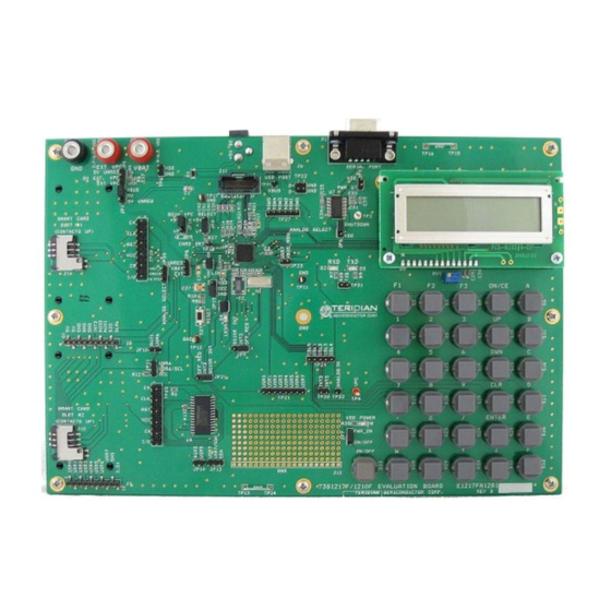
73S1217F Evaluation Board User’s Guide UG_1217F_040 PCB Layouts Figure 8: 73S1217F Evaluation Board Top View (Silkscreen) Rev. 2.4... -
Page 21: Figure 14: 73S1217F Evaluation Board Bottom View (Silkscreen)
UG_1217F_040 73S1217F Evaluation Board User’s Guide Figure 9: 73S1217F Evaluation Board Bottom View (Silkscreen) Rev. 2.4... -
Page 22: Figure 15: 73S1217F Evaluation Board Top Signal Layer
73S1217F Evaluation Board User’s Guide UG_1217F_040 Figure 10: 73S1217F Evaluation Board Top Signal Layer Rev. 2.4... -
Page 23: Figure 16: 73S1217F Evaluation Board Middle Layer 1 - Ground Plane
UG_1217F_040 73S1217F Evaluation Board User’s Guide Figure 11: 73S1217F Evaluation Board Middle Layer 1 – Ground Plane Rev. 2.4... -
Page 24: Figure 17: 73S1217F Evaluation Board Middle Layer 2 - Supply Plane
73S1217F Evaluation Board User’s Guide UG_1217F_040 Figure 12: 73S1217F Evaluation Board Middle Layer 2 – Supply Plane Rev. 2.4... -
Page 25: Figure 18: 73S1217F Evaluation Board Bottom Signal Layer
UG_1217F_040 73S1217F Evaluation Board User’s Guide Figure 13: 73S1217F Evaluation Board Bottom Signal Layer Rev. 2.4... -
Page 26: Bill Of Materials
73S1217F Evaluation Board User’s Guide UG_1217F_040 Bill of Materials Table 4 provides the bill of materials for the 73S1217F Evaluation Board schematic provided in Figure Table 4: 73S1217F Evaluation Board Bill of Materials Digi-key Part Item Qty. Reference Part PCB Footprint... - Page 27 UG_1217F_040 73S1217F Evaluation Board User’s Guide Digi-key Part Item Qty. Reference Part PCB Footprint Part Number Manufacturer Number +5 VDC RAPC712 SC1152-ND RAPC712 Switchcraft DB9_RS232 AMP_745781 A2100-ND 745781-4 AMP/Tyco Electronics 10 kΩ 3266W 3266W-103-ND 3266W-1-103 Bourns 0 Ω R1,R6,R27 P0.0GCT-ND...
- Page 28 73S1217F Evaluation Board User’s Guide UG_1217F_040 Digi-key Part Item Qty. Reference Part PCB Footprint Part Number Manufacturer Number TP27 HEADER 6 6 x 1 pin S1011E-36-ND PBC36SAAN Sullins Electronics TP29 HEADER 5 5 x 1 pin S1011E-36-ND PBC36SAAN Sullins Electronics...
-
Page 29: Schematic Information
The RTC oscillator drives a standard 32.768 kHz watch crystal. Crystals of this type are accurate and do not require a high current oscillator circuit. The oscillator in the 73S1217F has been designed specifically to handle watch crystals and is compatible with their high impedance and limited power handling capability. -
Page 30: Lcd
The 73S1217F does not contain an on-chip LCD controller. However, an LCD module (with built-in controller) can be used with the 73S1217F via use of specific USR (GPIO) pins. The LCD API libraries support up to a 2 line/16 character display. -
Page 31: Smart Card Interface
10µF and a 0.1 µF capacitor are connected to provide proper decoupling for this input. • The PRES input on the 73S1217F contains a very weak pull down resistor. As a result, an additional external pull down resistor is recommended to prevent any system noise from triggering a false card event. -
Page 32: Ordering Information
73S1217F Evaluation Board Quick Start Guide TSC Flash Programmer Model TFP2 User’s Manual 7 Contact Information For more information about Teridian Semiconductor products or to check the availability of the 73S1217F contact us at: 6440 Oak Canyon Road Suite 100... -
Page 33: Revision History
UG_1217F_040 73S1217F Evaluation Board User Guide Revision History Revision Date Description September 25, 2007 First Publication. November 29, 2007 Updated to Rev B PWB and added emulator usage and Schematic descriptions. January 3, 2007 Removed pull up resistors and 1000 pF capacitor from ICE interface and added LED0 jumper description. - Page 34 Mouser Electronics Authorized Distributor Click to View Pricing, Inventory, Delivery & Lifecycle Information: Maxim Integrated 73S1217F-EB...
Need help?
Do you have a question about the 73S1217F and is the answer not in the manual?
Questions and answers